Tow BMW 6 SERIES CONVERTIBLE 2014 F12 User Guide
[x] Cancel search | Manufacturer: BMW, Model Year: 2014, Model line: 6 SERIES CONVERTIBLE, Model: BMW 6 SERIES CONVERTIBLE 2014 F12Pages: 255, PDF Size: 5.37 MB
Page 122 of 255
Setting the warning timeThe warning time can be set via iDrive.1."Settings"2."Frontal Coll. Warning"3.Activate the desired time on the Control
Display.
The selected time is stored for the profile cur‐
rently in use.
Warning with braking function
Note Adapting your speed and driving style
The warning does not relieve the driver
of the responsibility to adapt his or her driving
speed and style to the traffic conditions.◀
Display
If a collision with a recognized vehicle is immi‐
nent a warning symbol appears in the instru‐
ment cluster and in the Head-Up Display.
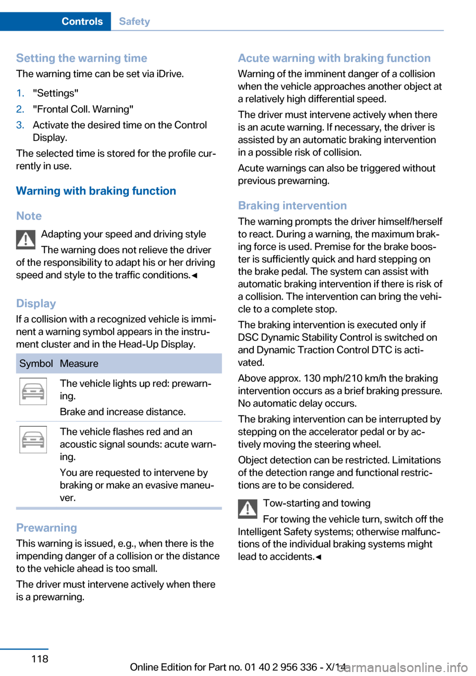
SymbolMeasureThe vehicle lights up red: prewarn‐
ing.
Brake and increase distance.The vehicle flashes red and an
acoustic signal sounds: acute warn‐
ing.
You are requested to intervene by
braking or make an evasive maneu‐
ver.
Prewarning
This warning is issued, e.g., when there is the
impending danger of a collision or the distance
to the vehicle ahead is too small.
The driver must intervene actively when there
is a prewarning.
Acute warning with braking function
Warning of the imminent danger of a collision
when the vehicle approaches another object at
a relatively high differential speed.
The driver must intervene actively when there
is an acute warning. If necessary, the driver is
assisted by an automatic braking intervention
in a possible risk of collision.
Acute warnings can also be triggered without
previous prewarning.
Braking intervention
The warning prompts the driver himself/herself
to react. During a warning, the maximum brak‐
ing force is used. Premise for the brake boos‐
ter is sufficiently quick and hard stepping on
the brake pedal. The system can assist with
automatic braking intervention if there is risk of
a collision. The intervention can bring the vehi‐
cle to a complete stop.
The braking intervention is executed only if
DSC Dynamic Stability Control is switched on
and Dynamic Traction Control DTC is acti‐
vated.
Above approx. 130 mph/210 km/h the braking
intervention occurs as a brief braking pressure.
No automatic delay occurs.
The braking intervention can be interrupted by
stepping on the accelerator pedal or by ac‐
tively moving the steering wheel.
Object detection can be restricted. Limitations
of the detection range and functional restric‐
tions are to be considered.
Tow-starting and towing
For towing the vehicle turn, switch off the
Intelligent Safety systems; otherwise malfunc‐
tions of the individual braking systems might
lead to accidents.◀Seite 118ControlsSafety118
Online Edition for Part no. 01 40 2 956 336 - X/14
Page 125 of 255
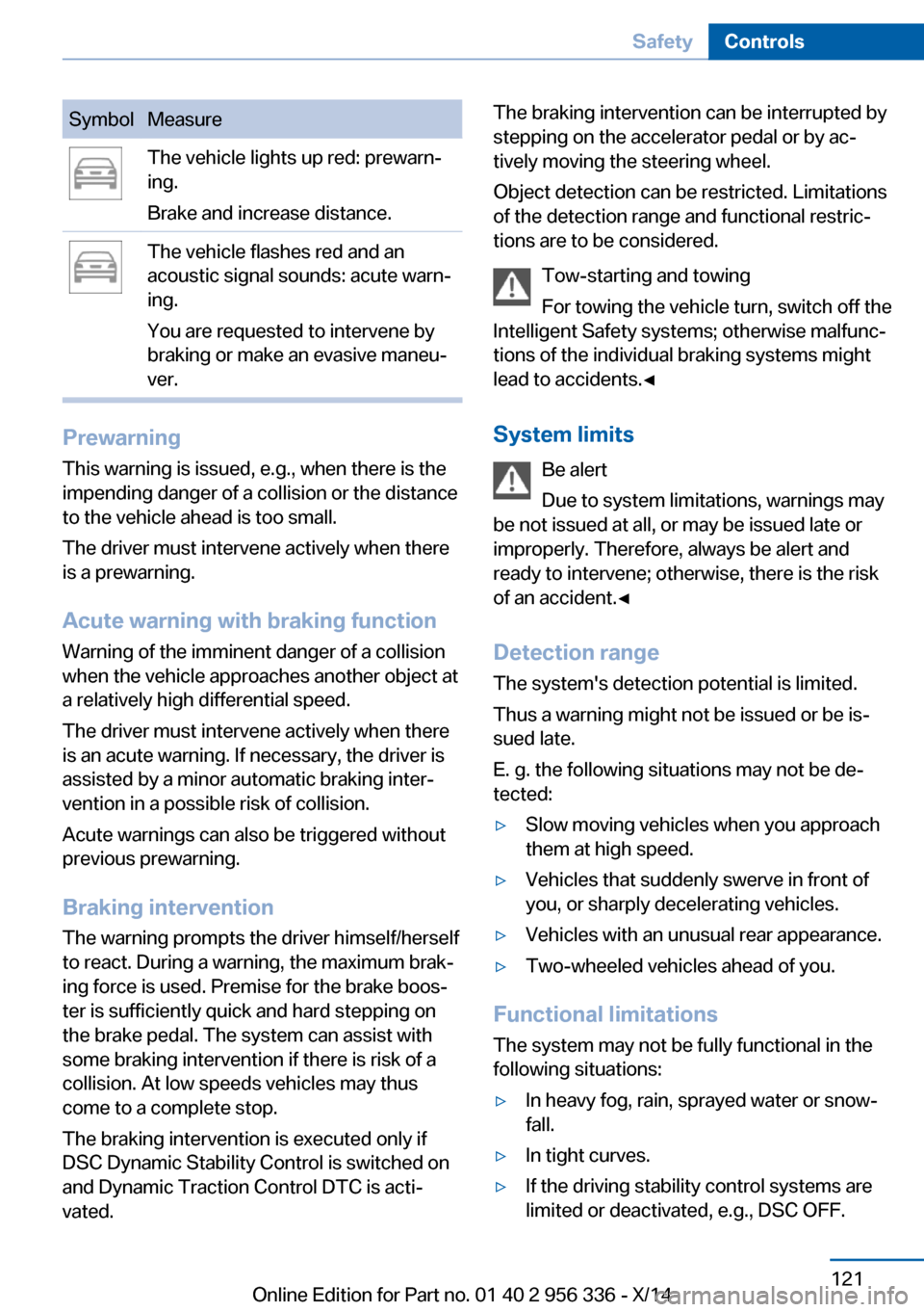
SymbolMeasureThe vehicle lights up red: prewarn‐
ing.
Brake and increase distance.The vehicle flashes red and an
acoustic signal sounds: acute warn‐
ing.
You are requested to intervene by
braking or make an evasive maneu‐
ver.
Prewarning
This warning is issued, e.g., when there is the
impending danger of a collision or the distance
to the vehicle ahead is too small.
The driver must intervene actively when there
is a prewarning.
Acute warning with braking function
Warning of the imminent danger of a collision
when the vehicle approaches another object at
a relatively high differential speed.
The driver must intervene actively when there
is an acute warning. If necessary, the driver is
assisted by a minor automatic braking inter‐
vention in a possible risk of collision.
Acute warnings can also be triggered without
previous prewarning.
Braking intervention The warning prompts the driver himself/herself
to react. During a warning, the maximum brak‐
ing force is used. Premise for the brake boos‐
ter is sufficiently quick and hard stepping on
the brake pedal. The system can assist with
some braking intervention if there is risk of a
collision. At low speeds vehicles may thus
come to a complete stop.
The braking intervention is executed only if
DSC Dynamic Stability Control is switched on
and Dynamic Traction Control DTC is acti‐
vated.
The braking intervention can be interrupted by
stepping on the accelerator pedal or by ac‐
tively moving the steering wheel.
Object detection can be restricted. Limitations
of the detection range and functional restric‐
tions are to be considered.
Tow-starting and towing
For towing the vehicle turn, switch off the
Intelligent Safety systems; otherwise malfunc‐
tions of the individual braking systems might
lead to accidents.◀
System limits Be alert
Due to system limitations, warnings may
be not issued at all, or may be issued late or
improperly. Therefore, always be alert and
ready to intervene; otherwise, there is the risk
of an accident.◀
Detection range The system's detection potential is limited.
Thus a warning might not be issued or be is‐
sued late.
E. g. the following situations may not be de‐
tected:▷Slow moving vehicles when you approach
them at high speed.▷Vehicles that suddenly swerve in front of
you, or sharply decelerating vehicles.▷Vehicles with an unusual rear appearance.▷Two-wheeled vehicles ahead of you.
Functional limitations
The system may not be fully functional in the
following situations:
▷In heavy fog, rain, sprayed water or snow‐
fall.▷In tight curves.▷If the driving stability control systems are
limited or deactivated, e.g., DSC OFF.Seite 121SafetyControls121
Online Edition for Part no. 01 40 2 956 336 - X/14
Page 128 of 255
Tow-starting and towing
For towing the vehicle turn, switch off the
Intelligent Safety systems; otherwise malfunc‐
tions of the individual braking systems might
lead to accidents.◀
System limits Be alert
Due to system limitations, warnings may
be not issued at all, or may be issued late or
improperly. Therefore, always be alert and
ready to intervene; otherwise, there is the risk
of an accident.◀
Detection range
The detection potential of the camera is lim‐
ited.
Thus a warning might not be issued or be is‐
sued late.
E. g. the following situations may not be de‐
tected:▷Partially covered pedestrians.▷Pedestrians that are not detected as such
because of the viewing angle or contour.▷Pedestrians outside of the detection range.▷Pedestrians having a body size less than
32 in/80 cm.
Functional limitations
The system may not be fully functional or may
not be available in the following situations:
▷In heavy fog, rain, sprayed water or snow‐
fall.▷In tight curves.▷If the driving stability control systems are
deactivated, e.g. DSC OFF.▷If the camera viewing field or the front
windshield are dirty or covered.▷Up to 10 seconds after the start of the en‐
gine, via the Start/Stop knob.▷During calibration of the camera immedi‐
ately after vehicle shipment.▷If there is constant blinding effects be‐
cause of oncoming light, e.g., from the sun
low in the sky.▷When it is dark outside.
Night Vision with Pedestrian
and Animal Detection
The concept Night Vision with pedestrian and animal detec‐
tion is a night vision system.
An infrared camera scans the area in front of
the vehicle and issues a warning if it detects
pedestrians and animals on the street. Warm
objects that are similar in shape to human be‐
ings or animals are detected by the system. If necessary, the heat image can be displayed on
the Control Display.
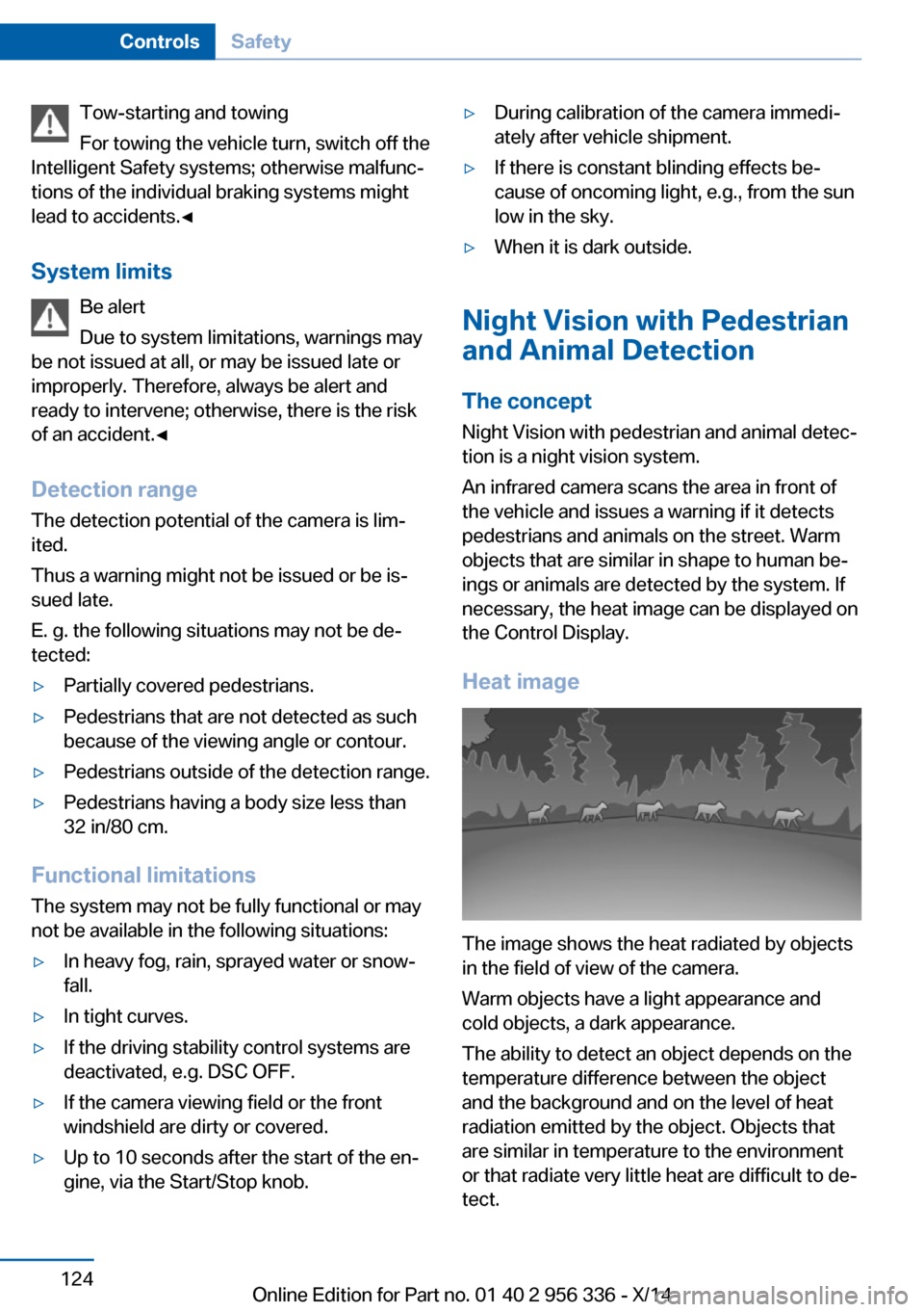
Heat image
The image shows the heat radiated by objects
in the field of view of the camera.
Warm objects have a light appearance and
cold objects, a dark appearance.
The ability to detect an object depends on the
temperature difference between the object
and the background and on the level of heat
radiation emitted by the object. Objects that
are similar in temperature to the environment
or that radiate very little heat are difficult to de‐
tect.
Seite 124ControlsSafety124
Online Edition for Part no. 01 40 2 956 336 - X/14
Page 130 of 255
The camera is automatically cleaned together
with the headlights.
Switching on/off
Switching on automatically When it is dark outside, the system is automat‐
ically active after every driving-off.
Switch off The system is only switched off until the next
time the engine is started with the Start/Stop
button.
Press button.
The LED goes out.
Switching on heat image additionally The heat image from the Night Vision camera
can also be displayed on the Control Display.
This function has no effect on object detec‐
tion.
Press button.
The image from the camera is displayed on the
Control Display.
Adjustments via the iDrive With heat image switched on:1.Press the controller.2.Select brightness or contrast.▷ Select the symbol.▷ Select the symbol.3.Turn the controller until the desired setting
is reached, and press the controller.
Display
Warning of people or animals in
danger
If a collision with a person or an animal de‐
tected in this way is imminent, a warning sym‐
bol appears on the instrument cluster and in
the Head-up Display.
Although both the shape and the heat radiation
are analyzed, false warnings cannot be ruled
out.
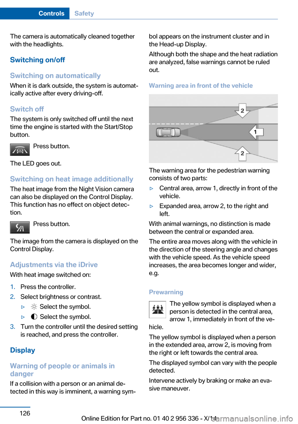
Warning area in front of the vehicle
The warning area for the pedestrian warning
consists of two parts:
▷Central area, arrow 1, directly in front of the
vehicle.▷Expanded area, arrow 2, to the right and
left.
With animal warnings, no distinction is made
between the central or expanded area.
The entire area moves along with the vehicle in
the direction of the steering angle and changes
with the vehicle speed. As the vehicle speed
increases, the area becomes longer and wider,
e.g.
Prewarning The yellow symbol is displayed when aperson is detected in the central area,
arrow 1, immediately in front of the ve‐
hicle.
The yellow symbol is displayed when a person
in the extended area, arrow 2, is moving from
the right or left towards the central area.
The displayed symbol can vary with the people
detected.
Intervene actively by braking or make an eva‐
sive maneuver.
Seite 126ControlsSafety126
Online Edition for Part no. 01 40 2 956 336 - X/14
Page 133 of 255
▷When lane markings are covered in snow,
ice, dirt or water.▷In tight curves or on narrow lanes.▷When the lane markings are covered by
objects.▷When driving very close to the vehicle in
front of you.▷When driving toward bright lights.▷When the windshield in front of the interior
rearview mirror is fogged over, dirty or cov‐
ered with stickers, etc.▷During calibration of the camera immedi‐
ately after vehicle shipment.
Active Blind Spot Detection
The concept
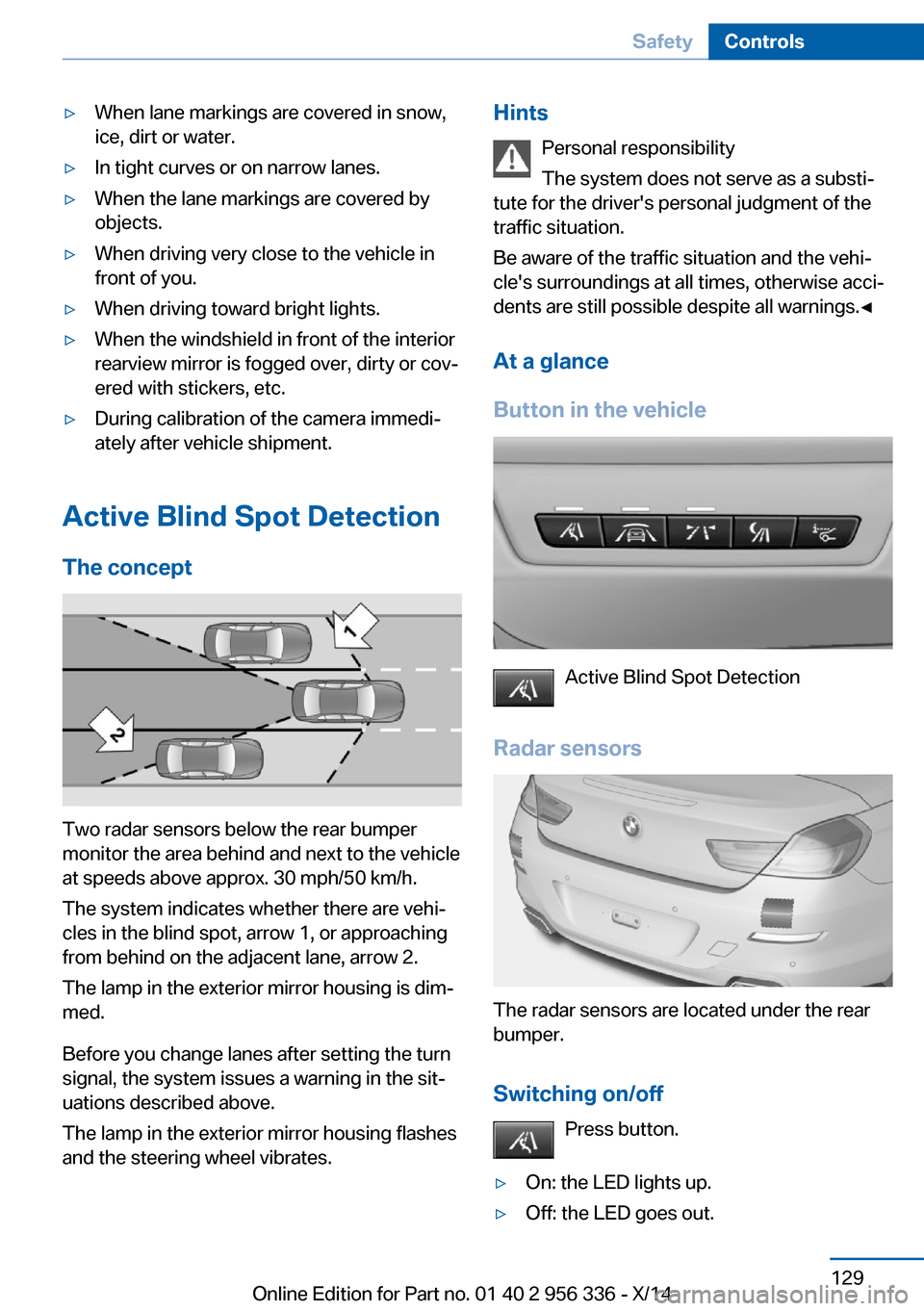
Two radar sensors below the rear bumper
monitor the area behind and next to the vehicle
at speeds above approx. 30 mph/50 km/h.
The system indicates whether there are vehi‐
cles in the blind spot, arrow 1, or approaching
from behind on the adjacent lane, arrow 2.
The lamp in the exterior mirror housing is dim‐
med.
Before you change lanes after setting the turn
signal, the system issues a warning in the sit‐
uations described above.
The lamp in the exterior mirror housing flashes
and the steering wheel vibrates.
Hints
Personal responsibility
The system does not serve as a substi‐
tute for the driver's personal judgment of the
traffic situation.
Be aware of the traffic situation and the vehi‐
cle's surroundings at all times, otherwise acci‐
dents are still possible despite all warnings.◀
At a glance
Button in the vehicle
Active Blind Spot Detection
Radar sensors
The radar sensors are located under the rear
bumper.
Switching on/off Press button.
▷On: the LED lights up.▷Off: the LED goes out.Seite 129SafetyControls129
Online Edition for Part no. 01 40 2 956 336 - X/14
Page 155 of 255
Switch the system back on if needed.
With front PDC: switching on/off
manually
Press button.▷On: the LED lights up.▷Off: the LED goes out.
Display
Signal tones When approaching an object, an intermittent
sound indicates the position of the object. E. g.
if an object is detected to the left rear of the
vehicle, a signal tone sounds from the left rear
speaker.
The shorter the distance to the object, the shorter the intervals.
If the distance to a detected object is less than
approx. 10 in/25 cm, a continuous tone is
sounded.
With front PDC: if objects are located both in
front of and behind the vehicle, an alternating
continuous signal is sounded.
An interval tone is interrupted with the appro‐
priate equipment after about 3 seconds:
▷If the vehicle stops in front of an object that
is detected by only one of the corner sen‐
sors.▷If moving parallel to a wall.
The signal tone is switched off:
▷When the vehicle moves away from an ob‐
ject by more than approx. 4 in/10 cm.▷When selector lever position P is engaged
on vehicles with Steptronic transmission.
Volume
The volume of the PDC signal tone can be ad‐
justed similar to the sound and volume set‐
tings of the radio.
Settings are stored for the profile currently in
use.
Visual warning
The approach of the vehicle to an object can
be shown on the Control Display. Objects that
are farther away are already displayed on the
Control Display before a signal sounds.
A display appears as soon as Park Distance
Control (PDC) is activated.
The range of the sensors is represented in the
colors green, yellow and red.
When the image of the rearview camera is dis‐
played, the reel can be made to PDC:
"Rear view camera"
System limits
Limits of ultrasonic measurement
Ultrasonic measuring might not function under
the following circumstances:
▷For small children and animals.▷For persons with certain clothing, e.g.
coats.▷With external interference of the ultra‐
sound, e.g. from passing vehicles or loud
machines.▷When sensors are dirty, iced over, dam‐
aged or out of position.▷Under certain weather conditions such as
high relative humidity, rain, snowfall, ex‐
treme heat or strong wind.▷With tow bars and trailer couplings of other
vehicles.▷With thin or wedge-shaped objects.▷With moving objects.▷With elevated, protruding objects such as
ledges or cargo.▷With objects with corners and sharp edges.▷With objects with a fine surface structure
such as fences.Seite 151Driving comfortControls151
Online Edition for Part no. 01 40 2 956 336 - X/14
Page 165 of 255
▷Possible on snow-covered or slippery road
surfaces.▷When there are obstacles that are hard to
overcome, such as curbs.▷When there are obstacles that suddenly
arise.▷If the Park Distance Control PDC displays
clearances that are too small.▷If a maximum number of parking attempts
or the time taken for parking is exceeded.▷If a turn signal has been actuated contrary
to the desired side for parking.▷When switching to another function on the
Control Display.
A Check Control message is displayed.
Resume An interrupted parking procedure can be con‐
tinued if needed.
Follow the instructions on the Control Display
to do this.
System limits
No parking assistance
The parking assistant does not offer assis‐
tance in the following situations:
▷In tight curves.
Functional limitations
The system may not be fully functional in the
following situations:
▷On bumpy road surfaces such as gravel
roads.▷On slippery ground.▷On steep uphill or downhill grades.▷With accumulations of leaves/snow in the
parking space.
Limits of ultrasonic measurement
Ultrasonic measuring might not function under
the following circumstances:
▷For small children and animals.▷For persons with certain clothing, e.g.
coats.▷With external interference of the ultra‐
sound, e.g. from passing vehicles or loud
machines.▷When sensors are dirty, iced over, dam‐
aged or out of position.▷Under certain weather conditions such as
high relative humidity, rain, snowfall, ex‐
treme heat or strong wind.▷With tow bars and trailer couplings of other
vehicles.▷With thin or wedge-shaped objects.▷With moving objects.▷With elevated, protruding objects such as
ledges or cargo.▷With objects with corners and sharp edges.▷With objects with a fine surface structure
such as fences.▷For objects with porous surfaces.
Low objects already displayed, e.g., curbs, can
move into the blind area of the sensors before
or after a continuous tone sounds.
The parking assistant may identify parking
spaces that are not suitable for parking.
Malfunction
A Check Control message is displayed.
The parking assistant failed. Have the system
checked.
Seite 161Driving comfortControls161
Online Edition for Part no. 01 40 2 956 336 - X/14
Page 169 of 255
This combined filter should be replaced during
scheduled maintenance, refer to page 215, of
your vehicle.
Ventilation
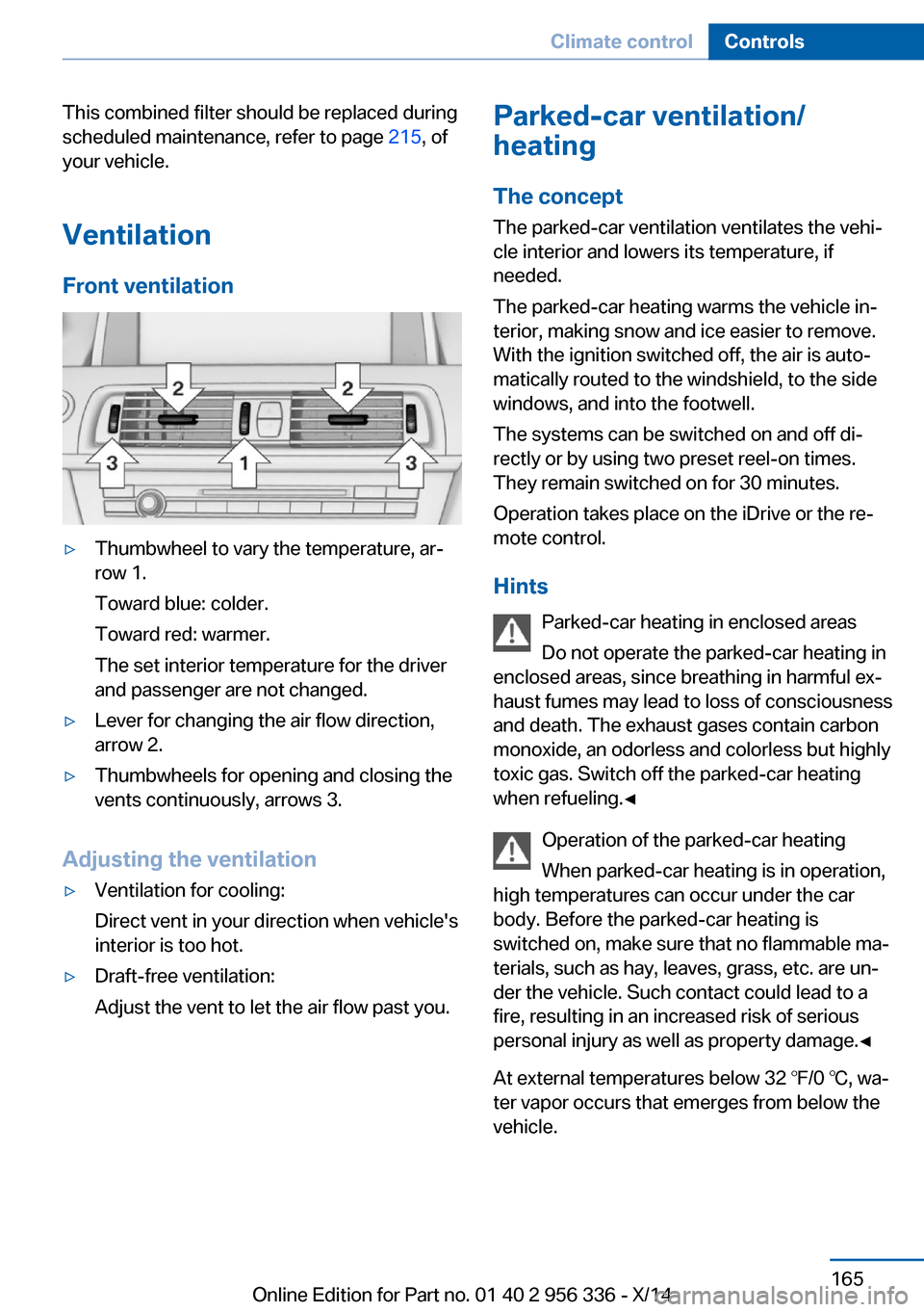
Front ventilation▷Thumbwheel to vary the temperature, ar‐
row 1.
Toward blue: colder.
Toward red: warmer.
The set interior temperature for the driver
and passenger are not changed.▷Lever for changing the air flow direction,
arrow 2.▷Thumbwheels for opening and closing the
vents continuously, arrows 3.
Adjusting the ventilation
▷Ventilation for cooling:
Direct vent in your direction when vehicle's
interior is too hot.▷Draft-free ventilation:
Adjust the vent to let the air flow past you.Parked-car ventilation/
heating
The concept The parked-car ventilation ventilates the vehi‐
cle interior and lowers its temperature, if
needed.
The parked-car heating warms the vehicle in‐
terior, making snow and ice easier to remove.
With the ignition switched off, the air is auto‐
matically routed to the windshield, to the side
windows, and into the footwell.
The systems can be switched on and off di‐
rectly or by using two preset reel-on times.
They remain switched on for 30 minutes.
Operation takes place on the iDrive or the re‐ mote control.
Hints Parked-car heating in enclosed areas
Do not operate the parked-car heating in
enclosed areas, since breathing in harmful ex‐
haust fumes may lead to loss of consciousness
and death. The exhaust gases contain carbon
monoxide, an odorless and colorless but highly
toxic gas. Switch off the parked-car heating
when refueling.◀
Operation of the parked-car heating
When parked-car heating is in operation,
high temperatures can occur under the car
body. Before the parked-car heating is switched on, make sure that no flammable ma‐
terials, such as hay, leaves, grass, etc. are un‐
der the vehicle. Such contact could lead to a
fire, resulting in an increased risk of serious
personal injury as well as property damage.◀
At external temperatures below 32 ℉/0 ℃, wa‐
ter vapor occurs that emerges from below the
vehicle.Seite 165Climate controlControls165
Online Edition for Part no. 01 40 2 956 336 - X/14
Page 176 of 255
Ski bag
Capacity The ski bag makes it possible to transport two
pairs of skis up to a length of 6 ft/2.10 m.
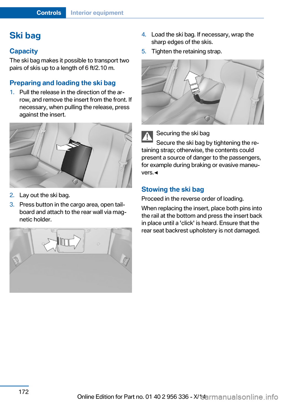
Preparing and loading the ski bag1.Pull the release in the direction of the ar‐
row, and remove the insert from the front. If
necessary, when pulling the release, press
against the insert.2.Lay out the ski bag.3.Press button in the cargo area, open tail‐
board and attach to the rear wall via mag‐
netic holder.4.Load the ski bag. If necessary, wrap the
sharp edges of the skis.5.Tighten the retaining strap.
Securing the ski bag
Secure the ski bag by tightening the re‐
taining strap; otherwise, the contents could
present a source of danger to the passengers,
for example during braking or evasive maneu‐
vers.◀
Stowing the ski bag Proceed in the reverse order of loading.
When replacing the insert, place both pins into
the rail at the bottom and press the insert back
in place until a 'click' is heard. Ensure that the
rear seat backrest upholstery is not damaged.
Seite 172ControlsInterior equipment172
Online Edition for Part no. 01 40 2 956 336 - X/14
Page 177 of 255
Storage compartmentsVehicle features and optionsThis chapter describes all standard, country-
specific and optional features offered with the
series. It also describes features that are not
necessarily available in your car, e. g., due to
the selected options or country versions. This
also applies to safety-related functions and
systems.
Hints No loose objects in the car's interior
Do not stow any objects in the car's inte‐
rior without securing them; otherwise, they
may present a danger to occupants e.g., during
braking and evasive maneuvers.◀
Do not place anti-slip mats on the dash‐
board
Do not place anti-slip mats on the dashboard.
The mat materials could damage the dash‐
board.◀
Storage compartments The following storage compartments are avail‐
able in the vehicle interior:▷Glove compartment on the front passenger
side, refer to page 173.▷Storage compartment in the center arm‐
rest, refer to page 174.▷Compartments in the doors.▷Pockets on the backrests of the front
seats.▷Net in the front passenger footwell.Glove compartment
Note Close the glove compartment again im‐
mediately
Close the glove compartment immediately af‐
ter use while driving; otherwise, injury may oc‐
cur during accidents.◀
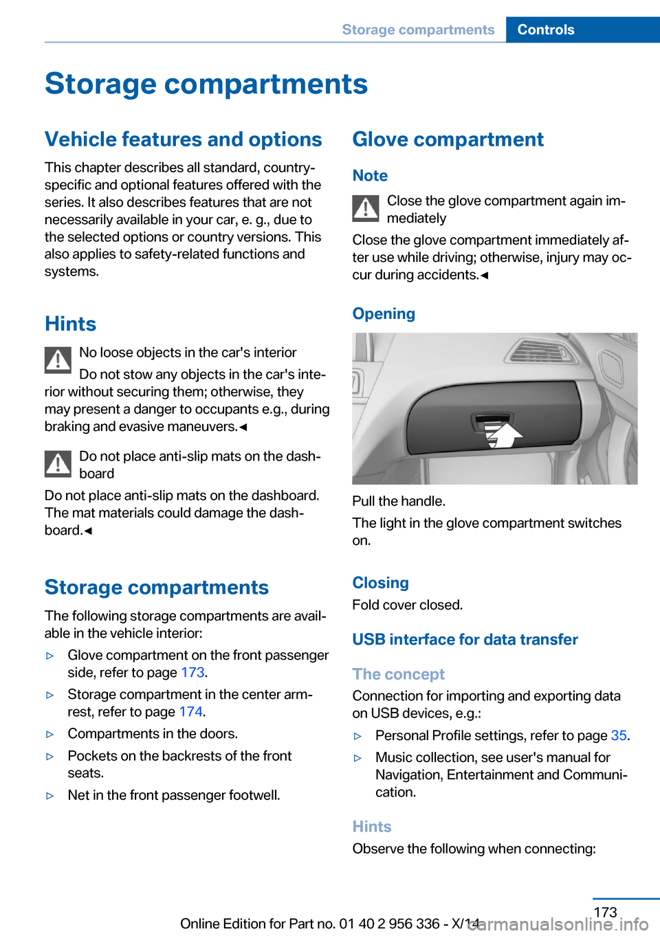
Opening
Pull the handle.
The light in the glove compartment switches
on.
ClosingFold cover closed.
USB interface for data transfer
The concept Connection for importing and exporting data
on USB devices, e.g.:
▷Personal Profile settings, refer to page 35.▷Music collection, see user's manual for
Navigation, Entertainment and Communi‐
cation.
Hints
Observe the following when connecting:
Seite 173Storage compartmentsControls173
Online Edition for Part no. 01 40 2 956 336 - X/14