BMW 6 SERIES COUPE 2013 F13 Owner's Manual
Manufacturer: BMW, Model Year: 2013, Model line: 6 SERIES COUPE, Model: BMW 6 SERIES COUPE 2013 F13Pages: 241, PDF Size: 7.05 MB
Page 151 of 241
Interrupting automaticallyThe system is interrupted automatically in the
following situations:▷If the driver grasps the steering wheel or if
he takes over steering.▷If a gear is selected that does not match
the instruction on the Control Display.▷If a turn signal is activated in the opposite
direction to the desired side for parking.▷If the vehicle speed exceeds approx.
6 mph/10 km/h.▷On snow-covered or slippery road surfaces
if necessary.▷If doors are open.▷When there are obstacles that are hard to
overcome, such as curbs.▷When there are obstacles that suddenly
arise.▷If a maximum number of parking attempts
or the time taken for parking is exceeded.
A Check Control message is displayed.
Continuing
An interrupted parking procedure can be con‐
tinued if necessary.
Follow the instructions on the Control Display
to do this.
System limits
No parking assistance The parking assistant does not offer assis‐
tance in the following situations:
▷In tight curves.
Functional limitations
The system may not be fully functional in the
following situations:
▷When sensors are dirty or iced over.▷In heavy fog, rain or snowfall.▷On bumpy road surfaces such as gravel
roads.▷On slippery ground.▷On steep uphill or downhill grades.▷When leaves or snow has collected in the
parking space.
Limits of ultrasonic measurement
The detection of objects can reach the physi‐
cal limits of ultrasonic measurement, e.g., in
the following circumstances:
▷With tow bars and trailer hitches.▷With thin or wedge-shaped objects.▷With elevated, protruding objects such as
ledges or cargo.▷With objects with corners and sharp edges.▷With objects with a fine surface structure,
such as fences.
Low objects already displayed, e.g., curbs, can
move into the blind area of the sensors before
or after a continuous tone sounds.
High, protruding objects such as ledges may
not be detected.
The parking assistant may identify parking
spaces that are not suitable for parking.
Malfunction
A Check Control message is displayed.
The parking assistant failed. Have the system
checked.
Seite 147Driving comfortControls147
Online Edition for Part no. 0140 2 910 771 - VI/13
Page 152 of 241
Head-up Display
The concept
This system projects important information
into the driver's field of vision, e.g., the speed.
In this way, the driver can get information with‐
out averting his or her eyes from the road.
Display visibility The visibility of the displays in the Head-up
Display is influenced by:
▷Certain sitting positions.▷Objects on the cover of the Head-up Dis‐
play.▷Sunglasses with certain polarization filters.▷Wet roads.▷Unfavorable light conditions.
If the image is distorted, check the basic set‐
tings.
Switching on/off
Press the button.
Display
Overview▷Speed.▷Navigation system.▷Check Control messages.▷Collision warning.▷Speed limit detection.▷Cruise control.▷Distance information.▷Congestion Assistant.▷Pedestrian warning.▷Selection list from the instrument cluster.
Some of this information is only displayed
briefly as needed.
Selecting displays in the Head-up
Display
1."Settings"2."Head-Up Display"3."Displayed information"4.Select the desired displays in the Head-up
Display.
The settings are stored for the remote control
currently in use.
Setting the brightness
The brightness is automatically adjusted to the
ambient light.
The basic setting can be adjusted manually.
1."Settings"2."Head-Up Display"3."Brightness"4.Turn the controller.
When the low beams are switched on, the
brightness of the Head-up Display can be ad‐
ditionally influenced using the instrument light‐
ing.
The setting is stored for the remote control
currently in use.
Seite 148ControlsDriving comfort148
Online Edition for Part no. 0140 2 910 771 - VI/13
Page 153 of 241
Adjusting the height1."Settings"2."Head-Up Display"3."Height"4.Turn the controller.
The setting is stored for the remote control
currently in use.
Setting the rotation
1."Settings"2."Head-Up Display"3."Rotation"4.Turn the controller.
The setting is stored for the remote control
currently in use.
Special windshield
The windshield is part of the system.
The shape of the windshield makes it possible
to display a precise image.
A film in the windshield prevents double im‐
ages from being displayed.
Therefore, have the special windshield re‐
placed by a service center only.
Distance information The conceptThe system displays a symbol in the Head-up
Display to indicate that the distance behind the
vehicle in front is not sufficient.
General information The distance is determined by the radar sen‐
sor of the Active Cruise Control.
Hints
Personal responsibility
The display does not relieve the driver of
the responsibility to adapt his or her distance
and driving style to the traffic conditions. Main‐
tain the prescribed safety distance.◀
At a glance
Radar sensor
A radar sensor is located in the front bumper
for detecting vehicles on the road ahead of the
vehicle.
A dirty or covered sensor may hinder the de‐
tection of vehicles.
▷If necessary, clean the radar sensor. Re‐
move layers of snow and ice carefully.▷Do not cover the view field of the radar
sensor.
Switching on
1.Switching on Head-Up Display, refer to
page 148.2."Distance info": Select the indication in the
Head-Up Display, refer to page 148.
Display in the Head-up Display
The symbol is displayed when the dis‐
tance from the vehicle traveling ahead
is too short.
Functional requirements
▷Active Cruise Control switched off.Seite 149Driving comfortControls149
Online Edition for Part no. 0140 2 910 771 - VI/13
Page 154 of 241
▷Display in the Head-up Display selected.▷Distance too short for longer than about
2 seconds.▷Speed greater than approx.
40 mph/70 km/h.
Malfunction
The system cannot be activated if the radar
sensor is not aligned correctly. This may be
caused by damage incurred during parking, for
example.
A Check Control message is displayed if the
system fails.
Seite 150ControlsDriving comfort150
Online Edition for Part no. 0140 2 910 771 - VI/13
Page 155 of 241
Climate controlVehicle equipment
All standard, country-specific and optional
equipment that is offered in the model series is
described in this chapter. Therefore, equip‐ment is also described that is not available in a
vehicle, e. g., because of the selected optional
equipment or country variant. This also applies
for safety-related functions and systems.
Automatic climate control
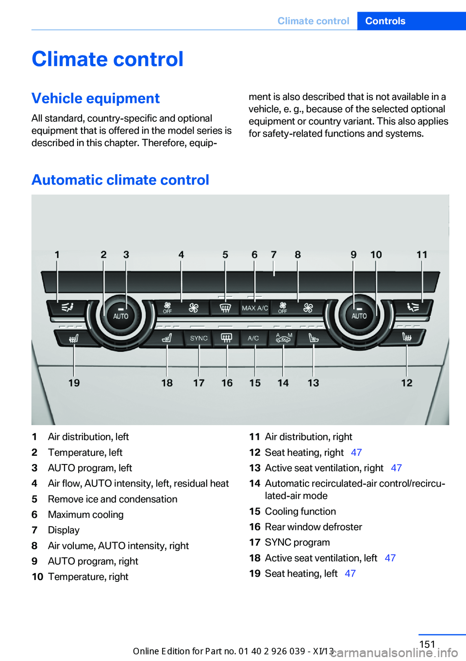
1Air distribution, left2Temperature, left3AUTO program, left4Air flow, AUTO intensity, left, residual heat5Remove ice and condensation6Maximum cooling7Display8Air volume, AUTO intensity, right9AUTO program, right10Temperature, right11Air distribution, right12Seat heating, right 4713Active seat ventilation, right 4714Automatic recirculated-air control/recircu‐
lated-air mode15Cooling function16Rear window defroster17SYNC program18Active seat ventilation, left 4719Seat heating, left 47Seite 151Climate controlControls151
Online Edition for Part no. 0140 2 910 771 - VI/13
Page 156 of 241
Climate control functions in detail
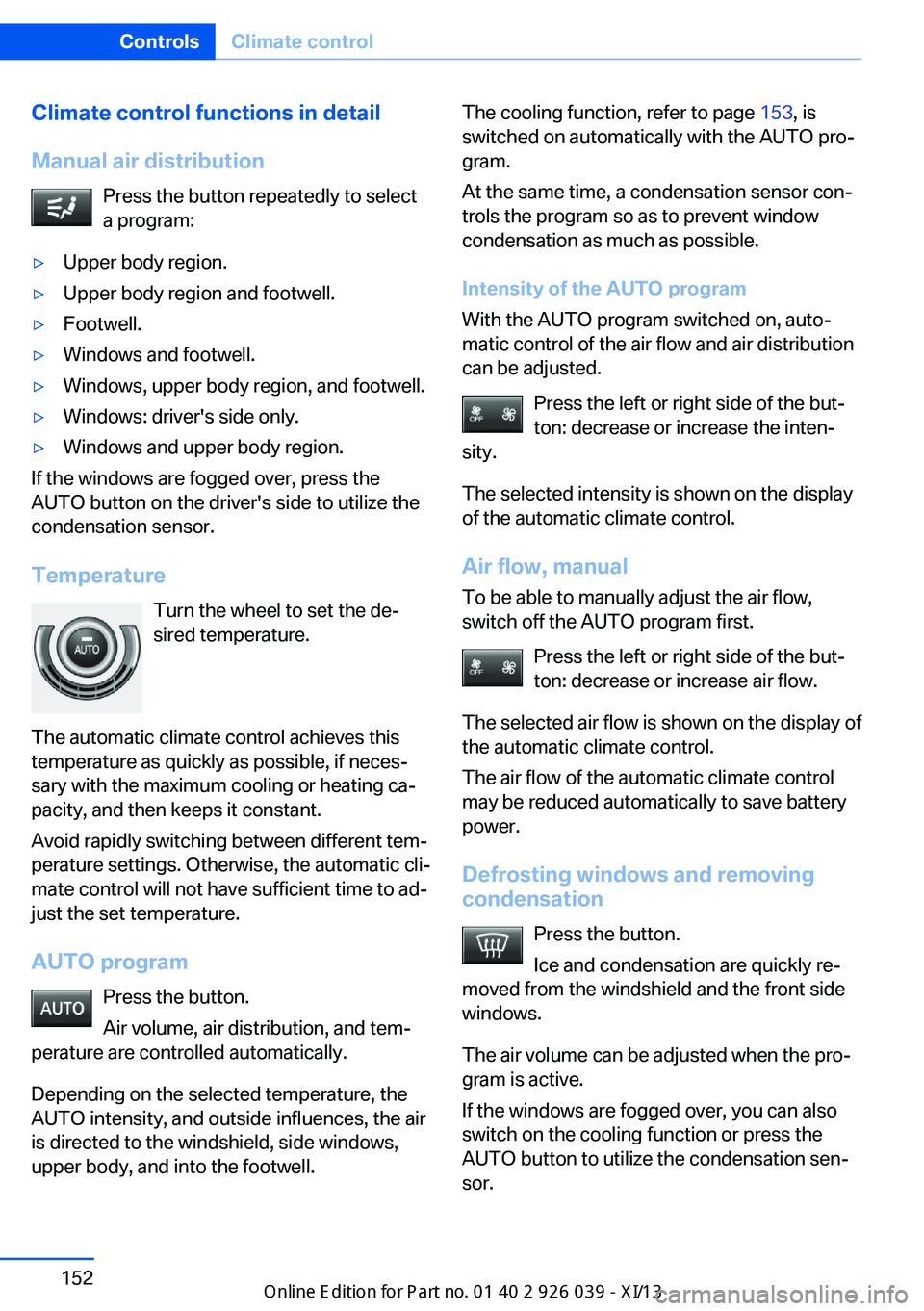
Manual air distribution Press the button repeatedly to select
a program:▷Upper body region.▷Upper body region and footwell.▷Footwell.▷Windows and footwell.▷Windows, upper body region, and footwell.▷Windows: driver's side only.▷Windows and upper body region.
If the windows are fogged over, press the
AUTO button on the driver's side to utilize the
condensation sensor.
Temperature Turn the wheel to set the de‐sired temperature.
The automatic climate control achieves this
temperature as quickly as possible, if neces‐
sary with the maximum cooling or heating ca‐
pacity, and then keeps it constant.
Avoid rapidly switching between different tem‐
perature settings. Otherwise, the automatic cli‐
mate control will not have sufficient time to ad‐
just the set temperature.
AUTO program Press the button.
Air volume, air distribution, and tem‐
perature are controlled automatically.
Depending on the selected temperature, the
AUTO intensity, and outside influences, the air
is directed to the windshield, side windows, upper body, and into the footwell.
The cooling function, refer to page 153, is
switched on automatically with the AUTO pro‐
gram.
At the same time, a condensation sensor con‐
trols the program so as to prevent window
condensation as much as possible.
Intensity of the AUTO program
With the AUTO program switched on, auto‐
matic control of the air flow and air distribution
can be adjusted.
Press the left or right side of the but‐
ton: decrease or increase the inten‐
sity.
The selected intensity is shown on the display
of the automatic climate control.
Air flow, manual To be able to manually adjust the air flow,
switch off the AUTO program first.
Press the left or right side of the but‐
ton: decrease or increase air flow.
The selected air flow is shown on the display of
the automatic climate control.
The air flow of the automatic climate control
may be reduced automatically to save battery
power.
Defrosting windows and removing condensation
Press the button.
Ice and condensation are quickly re‐
moved from the windshield and the front side
windows.
The air volume can be adjusted when the pro‐
gram is active.
If the windows are fogged over, you can also
switch on the cooling function or press the
AUTO button to utilize the condensation sen‐
sor.Seite 152ControlsClimate control152
Online Edition for Part no. 0140 2 910 771 - VI/13
Page 157 of 241
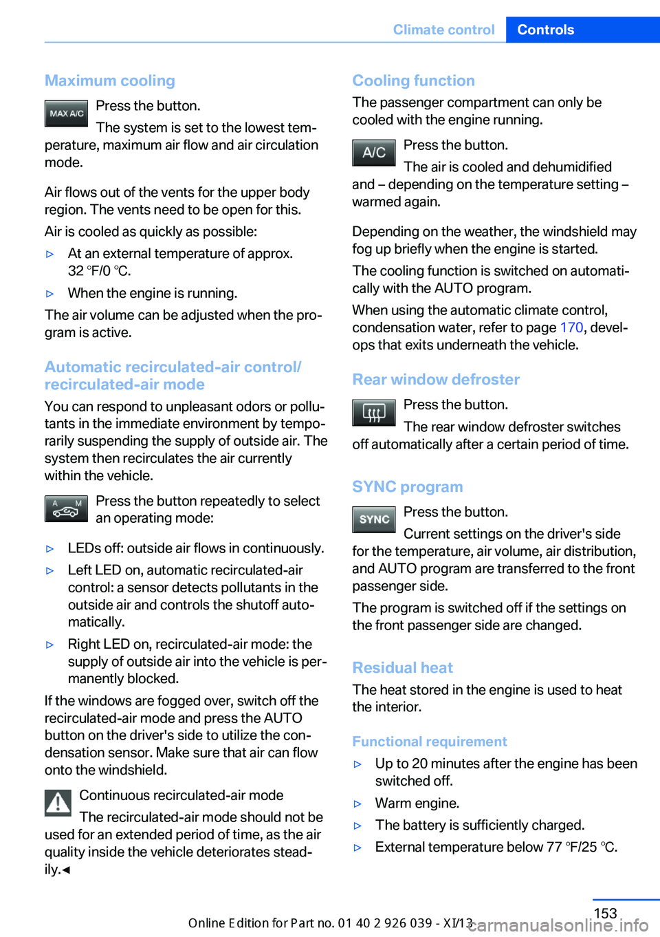
Maximum coolingPress the button.
The system is set to the lowest tem‐
perature, maximum air flow and air circulation
mode.
Air flows out of the vents for the upper body
region. The vents need to be open for this.
Air is cooled as quickly as possible:▷At an external temperature of approx.
32 ℉/0 ℃.▷When the engine is running.
The air volume can be adjusted when the pro‐
gram is active.
Automatic recirculated-air control/recirculated-air mode
You can respond to unpleasant odors or pollu‐
tants in the immediate environment by tempo‐
rarily suspending the supply of outside air. The
system then recirculates the air currently
within the vehicle.
Press the button repeatedly to select
an operating mode:
▷LEDs off: outside air flows in continuously.▷Left LED on, automatic recirculated-air
control: a sensor detects pollutants in the
outside air and controls the shutoff auto‐
matically.▷Right LED on, recirculated-air mode: the
supply of outside air into the vehicle is per‐
manently blocked.
If the windows are fogged over, switch off the
recirculated-air mode and press the AUTO
button on the driver's side to utilize the con‐
densation sensor. Make sure that air can flow
onto the windshield.
Continuous recirculated-air mode
The recirculated-air mode should not be
used for an extended period of time, as the air
quality inside the vehicle deteriorates stead‐
ily.◀
Cooling function
The passenger compartment can only be
cooled with the engine running.
Press the button.
The air is cooled and dehumidified
and – depending on the temperature setting –
warmed again.
Depending on the weather, the windshield may
fog up briefly when the engine is started.
The cooling function is switched on automati‐
cally with the AUTO program.
When using the automatic climate control,
condensation water, refer to page 170, devel‐
ops that exits underneath the vehicle.
Rear window defroster Press the button.
The rear window defroster switches
off automatically after a certain period of time.
SYNC program Press the button.
Current settings on the driver's side
for the temperature, air volume, air distribution,
and AUTO program are transferred to the front
passenger side.
The program is switched off if the settings on
the front passenger side are changed.
Residual heat
The heat stored in the engine is used to heat
the interior.
Functional requirement▷Up to 20 minutes after the engine has been
switched off.▷Warm engine.▷The battery is sufficiently charged.▷External temperature below 77 ℉/25 ℃.Seite 153Climate controlControls153
Online Edition for Part no. 0140 2 910 771 - VI/13
Page 158 of 241
Switching on1.Switch off the ignition.2. Press the right side of the button
on the driver's side.
The symbol appears on the automatic cli‐
mate Control Display.
The interior temperature, air volume and air
distribution can be adjusted with the ignition
switched on.
Switching off
At the lowest fan speed, press the left side of
the button on the driver's side.
The symbol on the display of the automatic
climate control flashes.
Switching the system on/off Switching off
▷Complete system: Press and hold the left button on
the driver's side until the control
clicks off.▷On the front passenger side:
Press and hold the left button on
the front passenger side.
Switching on
Press any button except:
▷SYNC program.▷Rear window defroster.▷Left side of Air volume button.▷Seat heating.▷Seat ventilation.
Microfilter/activated-charcoal filter
The microfilter removes dust and pollen from
the incoming air.
The activated-charcoal filter removes gaseous
pollutants from the outside air that enters the
vehicle.
This combined filter should be replaced during
scheduled maintenance, refer to page 202, of
your vehicle.
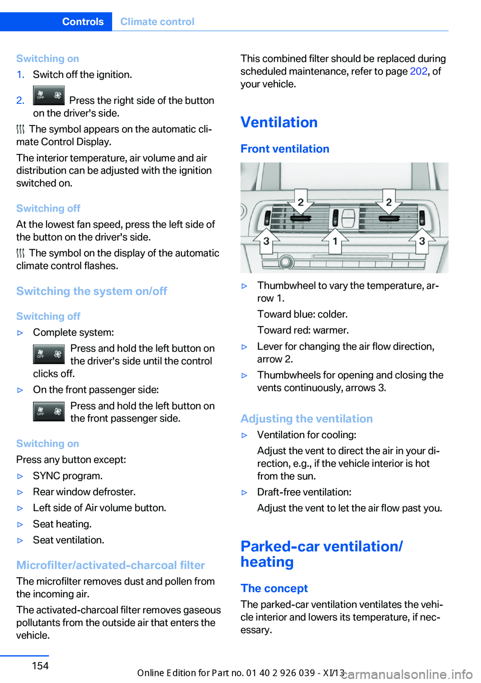
Ventilation Front ventilation▷Thumbwheel to vary the temperature, ar‐
row 1.
Toward blue: colder.
Toward red: warmer.▷Lever for changing the air flow direction,
arrow 2.▷Thumbwheels for opening and closing the
vents continuously, arrows 3.
Adjusting the ventilation
▷Ventilation for cooling:
Adjust the vent to direct the air in your di‐
rection, e.g., if the vehicle interior is hot
from the sun.▷Draft-free ventilation:
Adjust the vent to let the air flow past you.
Parked-car ventilation/
heating
The concept The parked-car ventilation ventilates the vehi‐
cle interior and lowers its temperature, if nec‐
essary.
Seite 154ControlsClimate control154
Online Edition for Part no. 0140 2 910 771 - VI/13
Page 159 of 241
The parked-car heating warms the vehicle in‐
terior, making snow and ice easier to remove.
With the ignition switched off, the air is auto‐
matically routed to the windshield, to the side
windows, and into the footwell.
The systems can be switched on and off di‐
rectly or by using two preset departure times.
The switch-on time is automatically deter‐
mined based on the temperature. The systems
promptly switch on before the selected depar‐
ture time.
Operation takes place on the iDrive or the re‐
mote control.
Note Parked-car heating in enclosed areas
Do not operate the parked-car heating in
enclosed areas, as breathing of the harmful ex‐
haust fumes may lead to loss of consciousness
and death. The exhaust gases contain carbon
monoxide, an odorless and colorless but highly
toxic gas. Switch off the parked-car heating
when refueling.◀
At external temperatures below 32 ℉/0 ℃, wa‐
ter vapor occurs that emerges from below the
vehicle.
Functional requirements
Parked-car ventilation▷With remote control or when the departure
time is preselected: depends on internal,
external and set temperature.▷Direct operation via iDrive: any external
temperature.▷In direct mode via remote control: external
temperature above approx. 59 ℉/15 ℃.
Open the vents to allow air to flow out.
Parked-car heating
▷With remote control or when the departure
time is preselected: depends on internal,
external and set temperature.▷Direct operation via iDrive: any external
temperature.▷In direct mode via remote control: external
temperature below approx. 59 ℉/15 ℃.▷The battery is sufficiently charged.▷The fuel tank is filled to above the reserve
range.
If the parked-car heating has not been used for
several months, it may be necessary to switch
the system on again after several minutes.
Switching on/off directly
1."Settings"2."Climate"3."Activate ind. heating" or
"Activate comf. ventilation"
The symbol on the automatic climate con‐
trol flashes if the system is switched on.
The system continues to run for some time af‐
ter being switched off.
Preselecting the departure time
1."Settings"2."Climate"3."Dep. time 1:" or "Dep. time 2:"4.Set the desired time.
Activating the departure time
1."Settings"2."Climate"3."Activate depart. time 1" or "Activate
depart. time 2"
The symbol on the automatic climate con‐
trol lights up when the departure time is acti‐
vated.
The symbol on the automatic climate con‐
trol flashes when the system has been
switched on.
The system will only be switched on within the
next 24 hours. After that, it needs to reacti‐
vated.
Seite 155Climate controlControls155
Online Edition for Part no. 0140 2 910 771 - VI/13
Page 160 of 241
Remote control
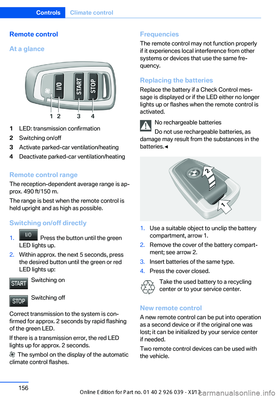
At a glance1LED: transmission confirmation2Switching on/off3Activate parked-car ventilation/heating4Deactivate parked-car ventilation/heating
Remote control range The reception-dependent average range is ap‐
prox. 490 ft/150 m.
The range is best when the remote control is
held upright and as high as possible.
Switching on/off directly
1. Press the button until the green
LED lights up.2.Within approx. the next 5 seconds, press
the desired button until the green or red
LED lights up:
Switching on
Switching off
Correct transmission to the system is con‐
firmed for approx. 2 seconds by rapid flashing
of the green LED.
If there is a transmission error, the red LED
lights up for approx. 2 seconds.
The symbol on the display of the automatic
climate control flashes.
Frequencies
The remote control may not function properly
if it experiences local interference from other
systems or devices that use the same fre‐
quency.
Replacing the batteries
Replace the battery if a Check Control mes‐
sage is displayed or if the LED either no longer
lights up or flashes when the remote control is
activated.
No rechargeable batteries
Do not use rechargeable batteries, as
damage may result from the substances in the
batteries.◀1.Use a suitable object to unclip the battery
compartment, arrow 1.2.Remove the cover of the battery compart‐
ment; see arrow 2.3.Insert batteries of the same type.4.Press the cover closed.
Take the used battery to a recycling
center or to your service center.
New remote control A new remote control can be put into operation
as a second device or if the original one was
lost; it can be initialized by your service center
if needed.
Two remote control devices can be used with
the vehicle.
Seite 156ControlsClimate control156
Online Edition for Part no. 0140 2 910 771 - VI/13