roof BMW 6 SERIES COUPE 2014 F13 Owner's Manual
[x] Cancel search | Manufacturer: BMW, Model Year: 2014, Model line: 6 SERIES COUPE, Model: BMW 6 SERIES COUPE 2014 F13Pages: 247, PDF Size: 5.08 MB
Page 21 of 247
10Driving Dynamics Control‚ÄÇ‚ÄÖ131DSC Dynamic Stability Con‚Äê
trol‚ÄÇ‚ÄÖ 12711Transmission selector lever
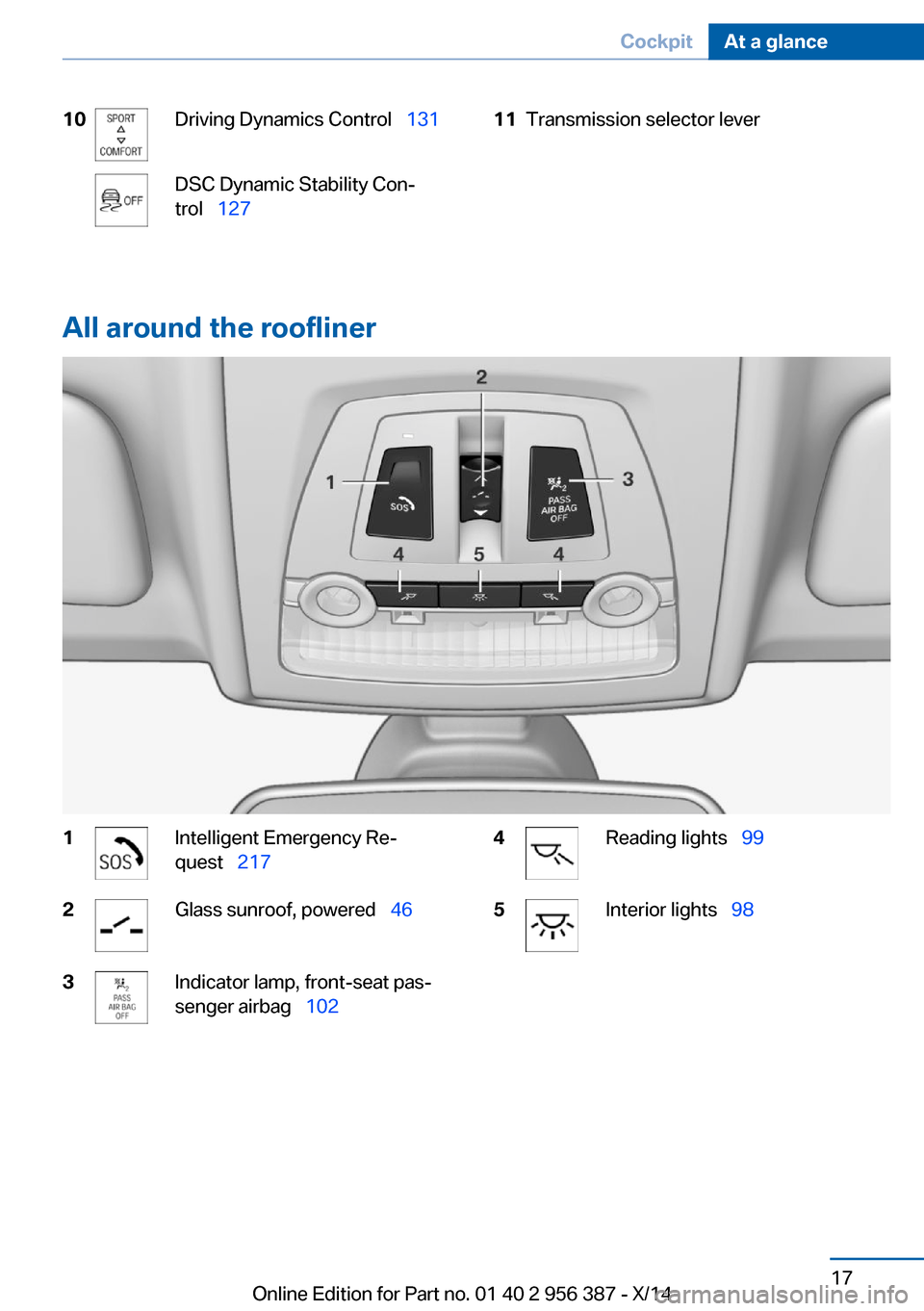
All around the roofliner
1Intelligent Emergency Re‚Äê
quest‚ÄÇ‚ÄÖ 2172Glass sunroof, powered‚ÄÇ‚ÄÖ 463Indicator lamp, front-seat pas‚Äê
senger airbag‚ÄÇ‚ÄÖ 1024Reading lights‚ÄÇ‚ÄÖ 995Interior lights‚ÄÇ‚ÄÖ98Seite 17CockpitAt a glance17
Online Edition for Part no. 01 40 2 956 387 - X/14
Page 32 of 247
This can unnecessarily delay the establish‚Äê
ment of a phone connection.
Instead, use the SOS button, refer to
page 217, close to the interior mirror.
Environmental conditions‚ñ∑Say the commands, numbers, and letters
smoothly and with normal volume, empha‚Äê
sis, and speed.‚ñ∑Always say commands in the language of
the voice activation system.‚ñ∑Keep the doors, windows, and glass sun‚Äê
roof closed to prevent noise interference.‚ñ∑Avoid making other noise in the vehicle
while speaking.Seite 28At a glanceVoice activation system28
Online Edition for Part no. 01 40 2 956 387 - X/14
Page 41 of 247
USB interface: "USB device"
Using the guest profile
The guest profile is for individual settings that
are saved in none of the three personal pro‚Äê
files.
This can be useful for drivers who are using
the vehicle temporarily and do not have their
own profile.
1."Settings"2."Profiles"3."Guest"
The guest profile cannot be renamed. It is not
assigned to the current remote control.
Display profile list during start
The profile list can be displayed during each
start to select the desired profile.
1."Settings"2."Profiles"3."Options"4."Display user list at startup"
Using the remote control
Note Take the remote control with youPeople or animals left unattended in a
parked vehicle can lock the doors from the in‚Äê
side. Always take the remote control with you
when leaving the vehicle so that the vehicle
can then be opened from the outside.‚óÄ
Unlocking Press button on the remote control.
‚ñ∑All doors and the trunk lid are unlocked.‚ñ∑Interior lamps and courtesy lamps are acti‚Äê
vated. This function is not available, if the
interior lamps were switched off manually.‚ñ∑The welcome lamps are switched on, if this
function was activated.‚ñ∑Exterior mirrors folded through convenient
closing are folded open.
You can set how the vehicle is to be unlocked.
For Settings, refer to page 42.
Anti-theft protection is switched off.
The alarm system, refer to page 43, is dis‚Äê
armed.
Convenient opening Press and hold this button on the re‚Äêmote control after unlocking.
The windows are opened, the glass sunroof is
tilted and the sliding visor moves back, as long
as the button on the remote control is pressed.
Locking Locking from the outside
Do not lock the vehicle from the outside
with people inside the car, as the vehicle can‚Äê
not be unlocked from inside without special knowledge.‚óÄ
Press button on the remote control.
All doors and the trunk lid are locked.
Anti-theft protection is switched on. It pre‚Äê
vents the doors from being unlocked using the
lock buttons or the door openers.
The alarm system, refer to page 43, is armed.
Switching on interior lights and
courtesy lights
Press button on the remote control with
the vehicle locked.
This function is not available, if the interior
lamps were switched off manually.
If the button is pressed again within 10 sec‚Äê
onds after vehicle was locked, the interior mo‚Äê
tion sensor and tilt alarm sensor of the anti-
Seite 37Opening and closingControls37
Online Edition for Part no. 01 40 2 956 387 - X/14
Page 45 of 247
Comfort AccessThe concept
The vehicle can be accessed without activat‚Äê
ing the remote control.
All you need to do is to have the remote con‚Äê
trol with you, such as in your pants pocket.
The vehicle automatically detects the remote
control when it is in close proximity or in the
car's interior.
Comfort Access supports the following func‚Äê
tions:‚ñ∑Unlocking/locking of the vehicle.‚ñ∑Convenient closing.‚ñ∑Open the trunk lid individually.‚ñ∑Start the engine.
Functional requirements
‚ñ∑There are no external sources of interfer‚Äê
ence nearby.‚ñ∑To lock the vehicle, the remote control
must be located outside of the vehicle.‚ñ∑The next unlocking and locking cycle is not
possible until after approx. 2 seconds.‚ñ∑The engine can only be started if the re‚Äê
mote control is in the vehicle.
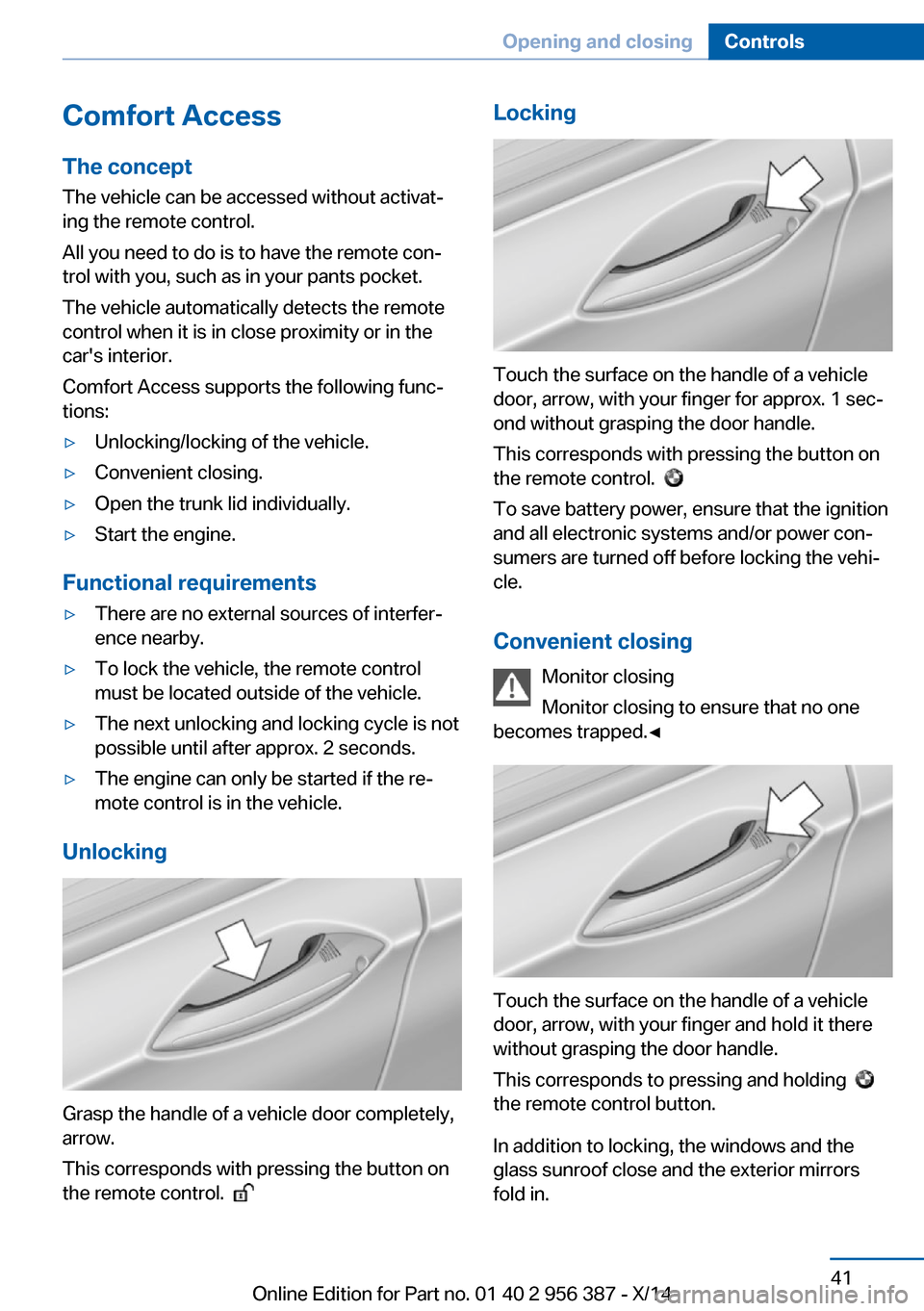
Unlocking
Grasp the handle of a vehicle door completely,
arrow.
This corresponds with pressing the button on
the remote control.
Locking
Touch the surface on the handle of a vehicle
door, arrow, with your finger for approx. 1 sec‚Äê
ond without grasping the door handle.
This corresponds with pressing the button on
the remote control.
To save battery power, ensure that the ignition
and all electronic systems and/or power con‚Äê
sumers are turned off before locking the vehi‚Äê
cle.
Convenient closing Monitor closing
Monitor closing to ensure that no one
becomes trapped.‚óÄ
Touch the surface on the handle of a vehicle
door, arrow, with your finger and hold it there
without grasping the door handle.
This corresponds to pressing and holding
the remote control button.
In addition to locking, the windows and the
glass sunroof close and the exterior mirrors
fold in.
Seite 41Opening and closingControls41
Online Edition for Part no. 01 40 2 956 387 - X/14
Page 48 of 247
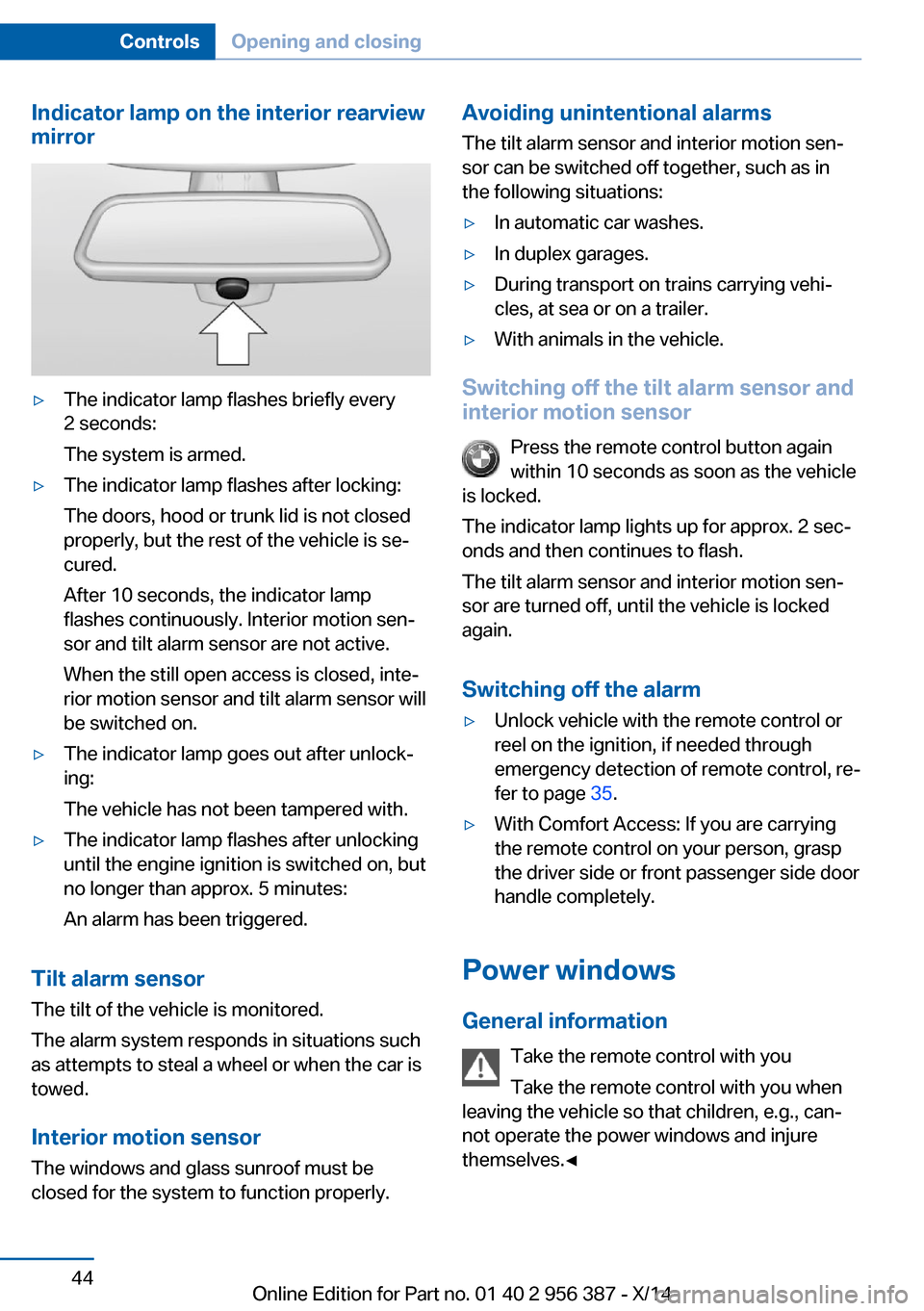
Indicator lamp on the interior rearview
mirror‚ñ∑The indicator lamp flashes briefly every
2 seconds:
The system is armed.‚ñ∑The indicator lamp flashes after locking:
The doors, hood or trunk lid is not closed
properly, but the rest of the vehicle is se‚Äê
cured.
After 10 seconds, the indicator lamp
flashes continuously. Interior motion sen‚Äê
sor and tilt alarm sensor are not active.
When the still open access is closed, inte‚Äê
rior motion sensor and tilt alarm sensor will
be switched on.‚ñ∑The indicator lamp goes out after unlock‚Äê
ing:
The vehicle has not been tampered with.‚ñ∑The indicator lamp flashes after unlocking
until the engine ignition is switched on, but
no longer than approx. 5 minutes:
An alarm has been triggered.
Tilt alarm sensor The tilt of the vehicle is monitored.
The alarm system responds in situations such
as attempts to steal a wheel or when the car is
towed.
Interior motion sensor The windows and glass sunroof must be
closed for the system to function properly.
Avoiding unintentional alarms
The tilt alarm sensor and interior motion sen‚Äê
sor can be switched off together, such as in
the following situations:‚ñ∑In automatic car washes.‚ñ∑In duplex garages.‚ñ∑During transport on trains carrying vehi‚Äê
cles, at sea or on a trailer.‚ñ∑With animals in the vehicle.
Switching off the tilt alarm sensor and
interior motion sensor
Press the remote control button again
within 10 seconds as soon as the vehicle
is locked.
The indicator lamp lights up for approx. 2 sec‚Äê
onds and then continues to flash.
The tilt alarm sensor and interior motion sen‚Äê
sor are turned off, until the vehicle is locked again.
Switching off the alarm
‚ñ∑Unlock vehicle with the remote control or
reel on the ignition, if needed through
emergency detection of remote control, re‚Äê
fer to page 35.‚ñ∑With Comfort Access: If you are carrying
the remote control on your person, grasp
the driver side or front passenger side door
handle completely.
Power windows
General information Take the remote control with you
Take the remote control with you when
leaving the vehicle so that children, e.g., can‚Äê
not operate the power windows and injure
themselves.‚óÄ
Seite 44ControlsOpening and closing44
Online Edition for Part no. 01 40 2 956 387 - X/14
Page 50 of 247
blocked for a limited time to prevent overheat‚Äê
ing. Let the system cool.
The roller sunblind for the rear window cannot
be moved at low interior temperatures.
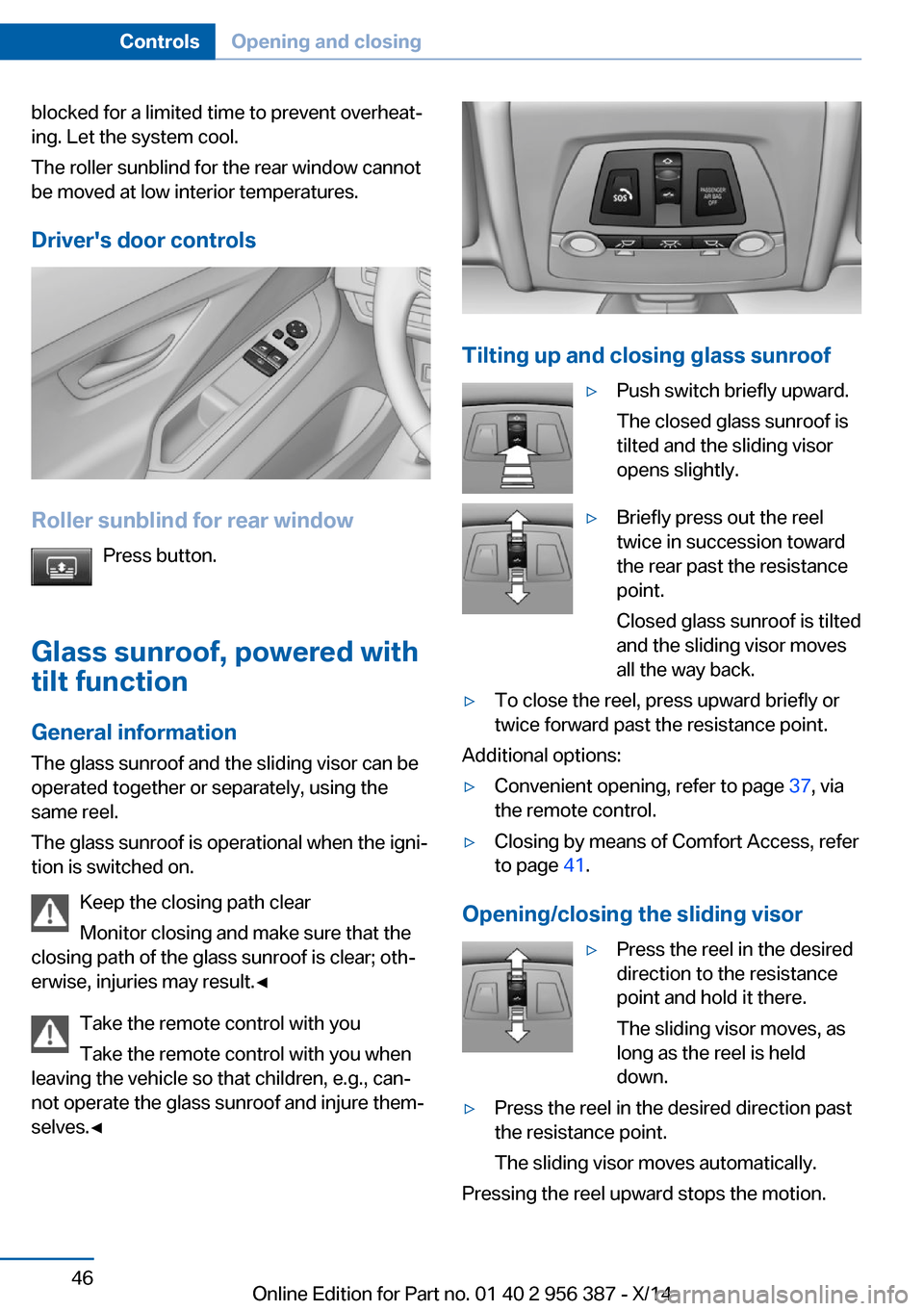
Driver's door controls
Roller sunblind for rear window Press button.
Glass sunroof, powered with tilt function
General information The glass sunroof and the sliding visor can be
operated together or separately, using the
same reel.
The glass sunroof is operational when the igni‚Äê
tion is switched on.
Keep the closing path clear
Monitor closing and make sure that the
closing path of the glass sunroof is clear; oth‚Äê
erwise, injuries may result.‚óÄ
Take the remote control with you
Take the remote control with you when
leaving the vehicle so that children, e.g., can‚Äê
not operate the glass sunroof and injure them‚Äê
selves.‚óÄ
Tilting up and closing glass sunroof
‚ñ∑Push switch briefly upward.
The closed glass sunroof is
tilted and the sliding visor
opens slightly.‚ñ∑Briefly press out the reel
twice in succession toward
the rear past the resistance
point.
Closed glass sunroof is tilted
and the sliding visor moves
all the way back.‚ñ∑To close the reel, press upward briefly or
twice forward past the resistance point.
Additional options:
‚ñ∑Convenient opening, refer to page 37, via
the remote control.‚ñ∑Closing by means of Comfort Access, refer
to page 41.
Opening/closing the sliding visor
‚ñ∑Press the reel in the desired
direction to the resistance
point and hold it there.
The sliding visor moves, as
long as the reel is held
down.‚ñ∑Press the reel in the desired direction past
the resistance point.
The sliding visor moves automatically.
Pressing the reel upward stops the motion.
Seite 46ControlsOpening and closing46
Online Edition for Part no. 01 40 2 956 387 - X/14
Page 51 of 247
Pinch protection systemIf the closing force exceeds a specific value as
a glass sunroof closes, the closing action is in‚Äê
terrupted.
The glass sunroof is tilted again.
Danger of jamming even with pinch pro‚Äê
tection
Despite the pinch protection system, check
that the glass sunroof's closing path is clear;
otherwise, the closing action may not be inter‚Äê
rupted in certain extreme situations, such as
when thin objects are present.‚óÄ
Closing without the pinch protection
system
If there is an external danger or if, e. g., icing
prevents automatic closing, push the reel for‚Äê
ward past the resistance point and hold it.
The glass sunroof closes without jam protec‚Äê
tion. Make sure that the closing area is clear.
Initializing after a power failure After a power failure during the opening or
closing process, the glass sunroof can only be
operated to a limited extent.
Initializing the system
The system can be initialized when the vehicle
is stationary and the engine is running.
During the initialization, the glass sunroof
closes without jam protection.
Keep the closing path clear
Monitor closing and make sure that the
closing path of the glass sunroof is clear; oth‚Äê
erwise, injuries may result.‚óÄ
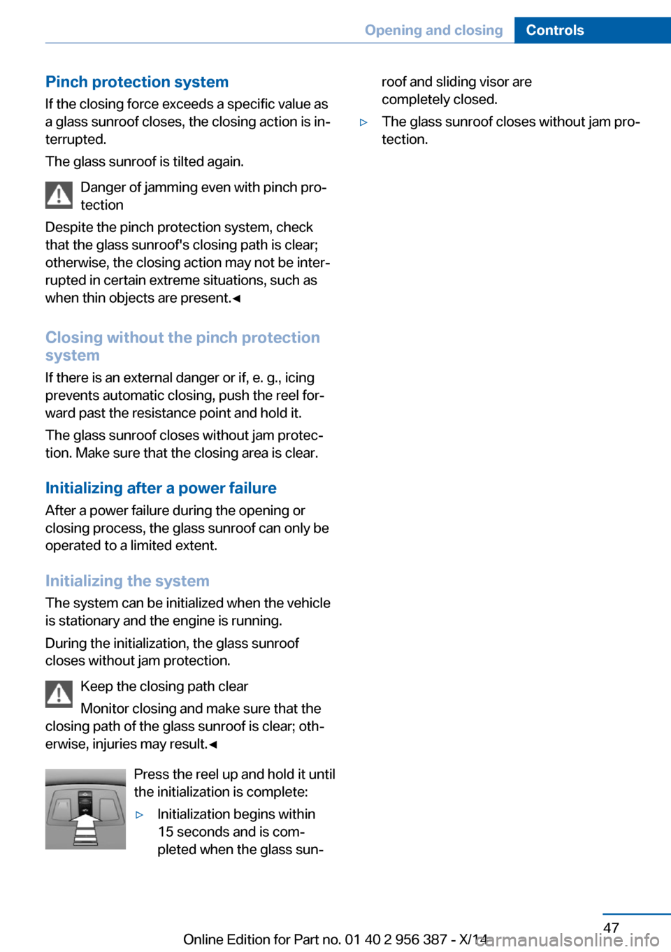
Press the reel up and hold it until
the initialization is complete:‚ñ∑Initialization begins within
15 seconds and is com‚Äê
pleted when the glass sun‚Äêroof and sliding visor are
completely closed.‚ñ∑The glass sunroof closes without jam pro‚Äê
tection.Seite 47Opening and closingControls47
Online Edition for Part no. 01 40 2 956 387 - X/14
Page 58 of 247
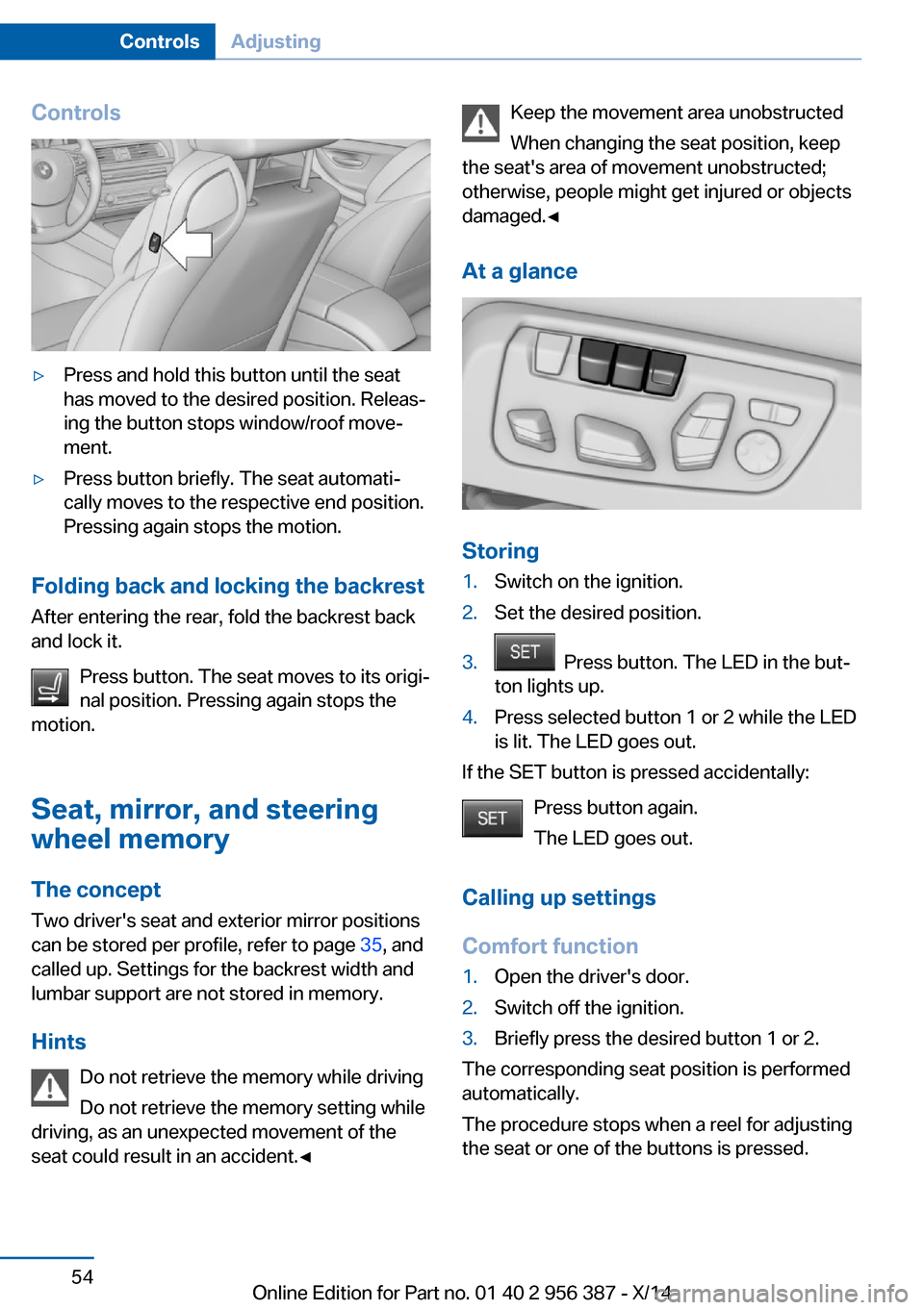
Controls‚ñ∑Press and hold this button until the seat
has moved to the desired position. Releas‚Äê
ing the button stops window/roof move‚Äê
ment.‚ñ∑Press button briefly. The seat automati‚Äê
cally moves to the respective end position.
Pressing again stops the motion.
Folding back and locking the backrest
After entering the rear, fold the backrest back
and lock it.
Press button. The seat moves to its origi‚Äê
nal position. Pressing again stops the
motion.
Seat, mirror, and steering
wheel memory
The concept
Two driver's seat and exterior mirror positions
can be stored per profile, refer to page 35, and
called up. Settings for the backrest width and
lumbar support are not stored in memory.
Hints Do not retrieve the memory while driving
Do not retrieve the memory setting while
driving, as an unexpected movement of the
seat could result in an accident.‚óÄ
Keep the movement area unobstructed
When changing the seat position, keep
the seat's area of movement unobstructed;
otherwise, people might get injured or objects
damaged.‚óÄ
At a glance
Storing
1.Switch on the ignition.2.Set the desired position.3. Press button. The LED in the but‚Äê
ton lights up.4.Press selected button 1 or 2 while the LED
is lit. The LED goes out.
If the SET button is pressed accidentally:
Press button again.
The LED goes out.
Calling up settings
Comfort function
1.Open the driver's door.2.Switch off the ignition.3.Briefly press the desired button 1 or 2.
The corresponding seat position is performed
automatically.
The procedure stops when a reel for adjusting
the seat or one of the buttons is pressed.
Seite 54ControlsAdjusting54
Online Edition for Part no. 01 40 2 956 387 - X/14
Page 105 of 247
Protective action
Airbags are not triggered in every impact situa‚Äê
tion, e.g., in less severe accidents or rear-end
collisions.
Information on how to ensure the optimal
protective effect of the airbags‚ñ∑Keep at a distance from the airbags.‚ñ∑Always grasp the steering wheel on the
steering wheel rim, holding your hands at
the 3 o'clock and 9 o'clock positions, to
keep the risk of injury to your hands or
arms as low as possible when the airbag is
triggered.‚ñ∑There should be no person, animals, or ob‚Äê
jects between an airbag and a person.‚ñ∑Do not use the cover of the front airbag on
the front passenger side as a storage area.‚ñ∑Dashboard and windshield on the front
passenger side must stay clear - do not at‚Äê
tach adhesive labels or coverings and do
not attach brackets or cables, e. g., for GPS
devices or' mobile phones.‚ñ∑Make sure that the front passenger is sit‚Äê
ting correctly, i.e., keeps his or her feet and
legs in the footwell; otherwise, leg injuries
might occur when front airbag is activated.‚ñ∑Do not place slip covers, seat cushions or
other objects on the front passenger seat
that are not approved specifically for seats
with integrated side airbags.‚ñ∑Do not hang pieces of clothing, such as
jackets, over the backrests.‚ñ∑Make sure that occupants keep their heads
away from the side airbag and do not rest
against the head airbag; otherwise, injuries
might occur when airbag is activated.‚ñ∑Do not remove the airbag system.‚ñ∑Do not remove the steering wheel.‚ñ∑Do not apply adhesive materials to the air‚Äê
bag cover panels, do not cover them or
modify them in any way.‚ñ∑Never modify either the individual compo‚Äê
nents or the wiring in the airbag system.
This also applies to steering wheel covers,
the dashboard, the seats, the roof pillars
and the sides of the roofliner.‚óÄ
Even when you follow all instructions very
closely, injury from contact with the airbags
cannot be ruled out in certain situations.
The ignition and inflation noise may lead to
short-term and, in most cases, temporary
hearing impairment in sensitive individuals.
Malfunction, deactivation and after de‚Äê
ploying the airbags
Do not touch the individual components imme‚Äê
diately after the system has been triggered;
otherwise, you may risk burns.
Only have the airbags checked, repaired or dis‚Äê
mantled and the airbag generator scrapped by
the service center or an authorized repair shop
for handling explosives.
Non-professional attempts to service the sys‚Äê
tem could lead to failure in an emergency or
unintentional activation of the airbag - both
may lead to injury.‚óÄ
Warnings and information on the airbags are also found on the sun visors.
Functional readiness of the airbag
system
When the ignition is reel on, the warn‚Äê
ing lamp in the instrument cluster lights
up briefly and thereby indicates the op‚Äê
erational readiness of the entire airbag system
and the belt tensioner.
Airbag system malfunctioning
‚ñ∑Warning lamp does not come on when the
ignition is turned on.‚ñ∑The warning lamp lights up continuously.Seite 101SafetyControls101
Online Edition for Part no. 01 40 2 956 387 - X/14
Page 129 of 247
A recommendation to take a break is displayed
only once during an uninterrupted trip.
After a break, another recommendation to take
a break cannot be displayed until after approxi‚Äê
mately 45 minutes.
System limits
The function may be limited in the following
situations, for instance, and will either output
an incorrect warning or no warning at all:‚ñ∑When the clock is set incorrectly.‚ñ∑When the vehicle speed is mainly below
about 43 mph/70 km/h.‚ñ∑With a sporty driving style, such as during
rapid acceleration or when cornering fast.‚ñ∑In active driving situations, such as when
changing lanes frequently.‚ñ∑When the road surface is poor.‚ñ∑In the event of strong side winds.
PreCrash
The concept With this system critical driving situations that
might result in an accident can be detected
above a speed of approx. 20 mph/30 km/h. In these situations, preventive measures are au‚Äê
tomatically taken to minimize the risk of an ac‚Äê
cident as much as possible.
Critical driving situations may include:
Emergency stop.
If the vehicle includes the front-end collision
warning or front-end collision warning with
braking feature, impending collisions with vehi‚Äê
cles driving ahead or stopped in front of you
can also be detected within the system's
range.
Note
Personal responsibility
The system cannot possibly serve as a
substitute for the driver's personal judgment of
the traffic situation. The system may not al‚Äê
ways detect critical situations reliably and in a
timely manner. Adapt speed to traffic situation
and drive alertly; otherwise, a risk to safety may
result.‚óÄ
Function
After the safety belt is buckled, the front belts
are automatically pretensioned once after the
vehicle is driven is away.
In critical driving situations, the following indi‚Äê
vidual functions become active as needed:‚ñ∑The front belts are automatically preten‚Äê
sioned.‚ñ∑Automatic closing of the windows.‚ñ∑Automatic closing of the glass sunroof.‚ñ∑For vehicles equipped with power backrest
adjustment: automatic positioning of the
backrest for the front passenger seat.
After a critical driving situation without an acci‚Äê
dent, the front belts are loosened again. All
other systems can be restored to the desired
setting.
If the belt tension does not loosen automati‚Äê
cally, stop the vehicle and unbuckle the belt
using the red button in the buckle. Fasten the
belt before continuing on your trip.
PostCrash
In the event of an accident, the system can
bring the car to a halt automatically without in‚Äê
tervention by the driver in certain situations.
This can reduce the risk of a further collision
and the consequences thereof.
Depressing the brake pedal can cause the ve‚Äê
hicle to brake harder. This interrupts automatic
braking. Destepping on the gas pedal also in‚Äê terrupts automatic braking.
Seite 125SafetyControls125
Online Edition for Part no. 01 40 2 956 387 - X/14