height BMW 6 SERIES GRAN COUPE 2014 F06 Owner's Manual
[x] Cancel search | Manufacturer: BMW, Model Year: 2014, Model line: 6 SERIES GRAN COUPE, Model: BMW 6 SERIES GRAN COUPE 2014 F06Pages: 253, PDF Size: 5.47 MB
Page 39 of 253
3.Remove the cover of the battery compart‐
ment, arrow 2.4.Insert a battery of the same type with the
positive side facing up.5.Press the cover closed.
Take the used battery to a recycling
center or to your service center.
New remote controls New remote controls are available from the
service center.
Loss of the remote controls Lost remote controls can be disabled by your
service center.
Emergency detection of remote
control
It is possible to reel on the ignition or start the
engine in situations such as the following:
▷Interference of radio transmission to re‐
mote control by external sources e.g., by
radio masts.▷Empty battery in remote control.▷Interference from radio transmissions
through mobile devices in close proximity
to remote control.▷Interference of radio transmission by
charger while charging items such as mo‐
bile devices in the vehicle.
A Check Control message is displayed if an at‐
tempt is made to reel on the ignition or start
the engine.
Starting the engine with emergency
detection of the remote control
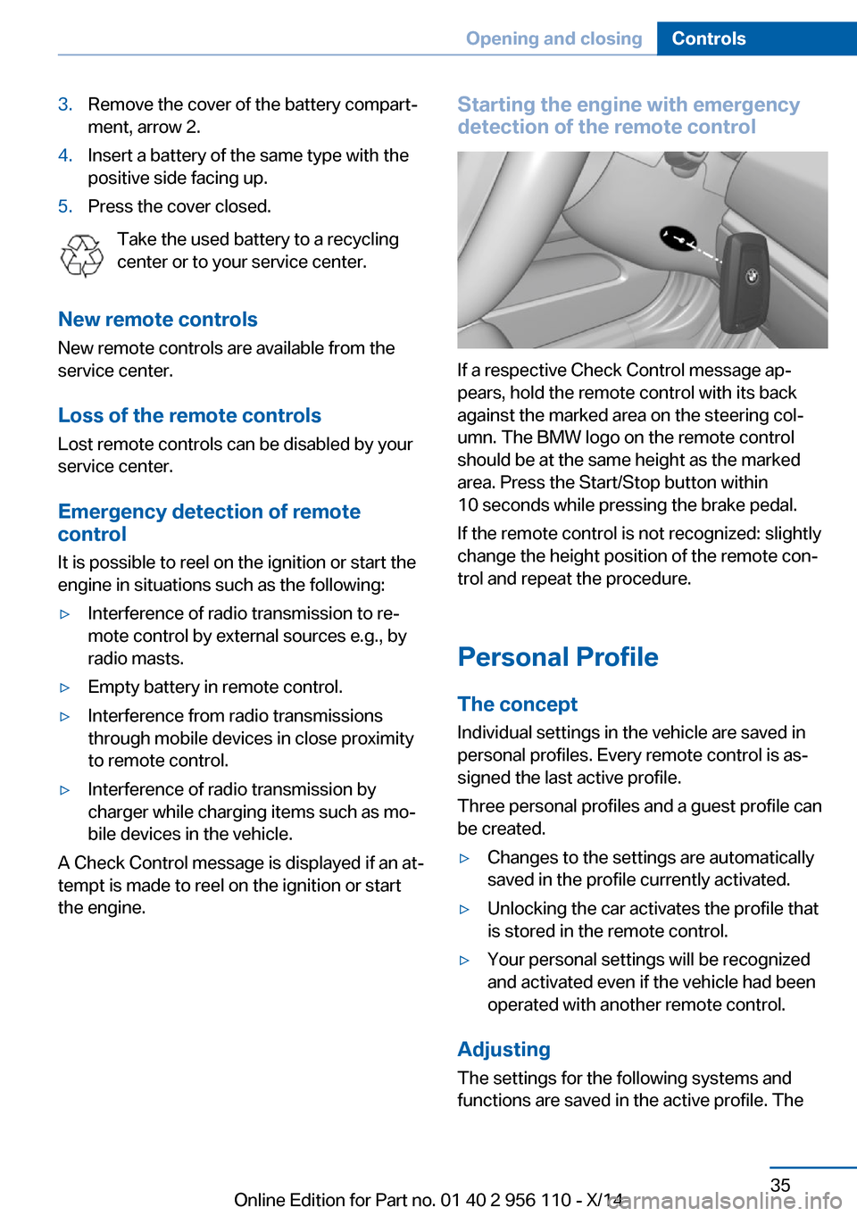
If a respective Check Control message ap‐
pears, hold the remote control with its back
against the marked area on the steering col‐
umn. The BMW logo on the remote control
should be at the same height as the marked
area. Press the Start/Stop button within
10 seconds while pressing the brake pedal.
If the remote control is not recognized: slightly
change the height position of the remote con‐
trol and repeat the procedure.
Personal Profile
The concept Individual settings in the vehicle are saved in
personal profiles. Every remote control is as‐
signed the last active profile.
Three personal profiles and a guest profile can
be created.
▷Changes to the settings are automatically
saved in the profile currently activated.▷Unlocking the car activates the profile that
is stored in the remote control.▷Your personal settings will be recognized
and activated even if the vehicle had been
operated with another remote control.
Adjusting
The settings for the following systems and
functions are saved in the active profile. The
Seite 35Opening and closingControls35
Online Edition for Part no. 01 40 2 956 110 - X/14
Page 53 of 253
AdjustingVehicle features and options
This chapter describes all standard, country-
specific and optional features offered with the
series. It also describes features that are not
necessarily available in your car, e. g., due to
the selected options or country versions. This
also applies to safety-related functions and
systems.
Sitting safely
The ideal seating position can make a vital
contribution to relaxed, fatigue-free driving.
The seating position plays an important role in
an accident in combination with:▷Safety belts, refer to page 52.▷Head restraints, refer to page 54.▷Airbags, refer to page 101.
Seats
Hints Do not adjust the seat while driving
Do not adjust the driver's seat while driv‐
ing, or the seat could respond with unexpected
movement and the ensuing loss of vehicle
control could lead to an accident.◀
Do not incline the backrest too far to the
rear
Also on the front passenger side, do not incline
the backrest on the front passenger side too far to the rear while driving, or there is a risk of
slipping under the safety belt in the event of an
accident. This would eliminate the protection
normally provided by the belt.◀
Keep the movement area unobstructed
When changing the seat position, keep
the seat's area of movement unobstructed;
otherwise, people might get injured or objects
damaged.◀
Middle seat
The 6 Series Gran Coupe is designed as a
4+1-seater vehicle.
The middle seat is of limited usefulness. It is
recommended that this seat only be used by
persons who can use the backrest as a substi‐
tute for the head restraint.
Adjusting the head restraints, refer to
page 54.
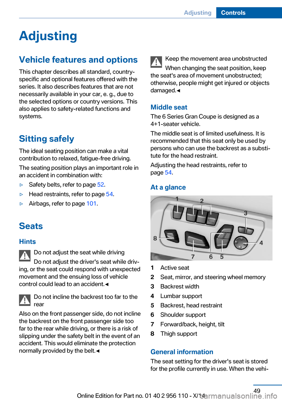
At a glance1Active seat2Seat, mirror, and steering wheel memory3Backrest width4Lumbar support5Backrest, head restraint6Shoulder support7Forward/back, height, tilt8Thigh support
General information
The seat setting for the driver's seat is stored
for the profile currently in use. When the vehi‐
Seite 49AdjustingControls49
Online Edition for Part no. 01 40 2 956 110 - X/14
Page 54 of 253
cle is unlocked via the remote control, the po‐
sition is automatically retrieved if the Function,
refer to page 43, is activated for this purpose.
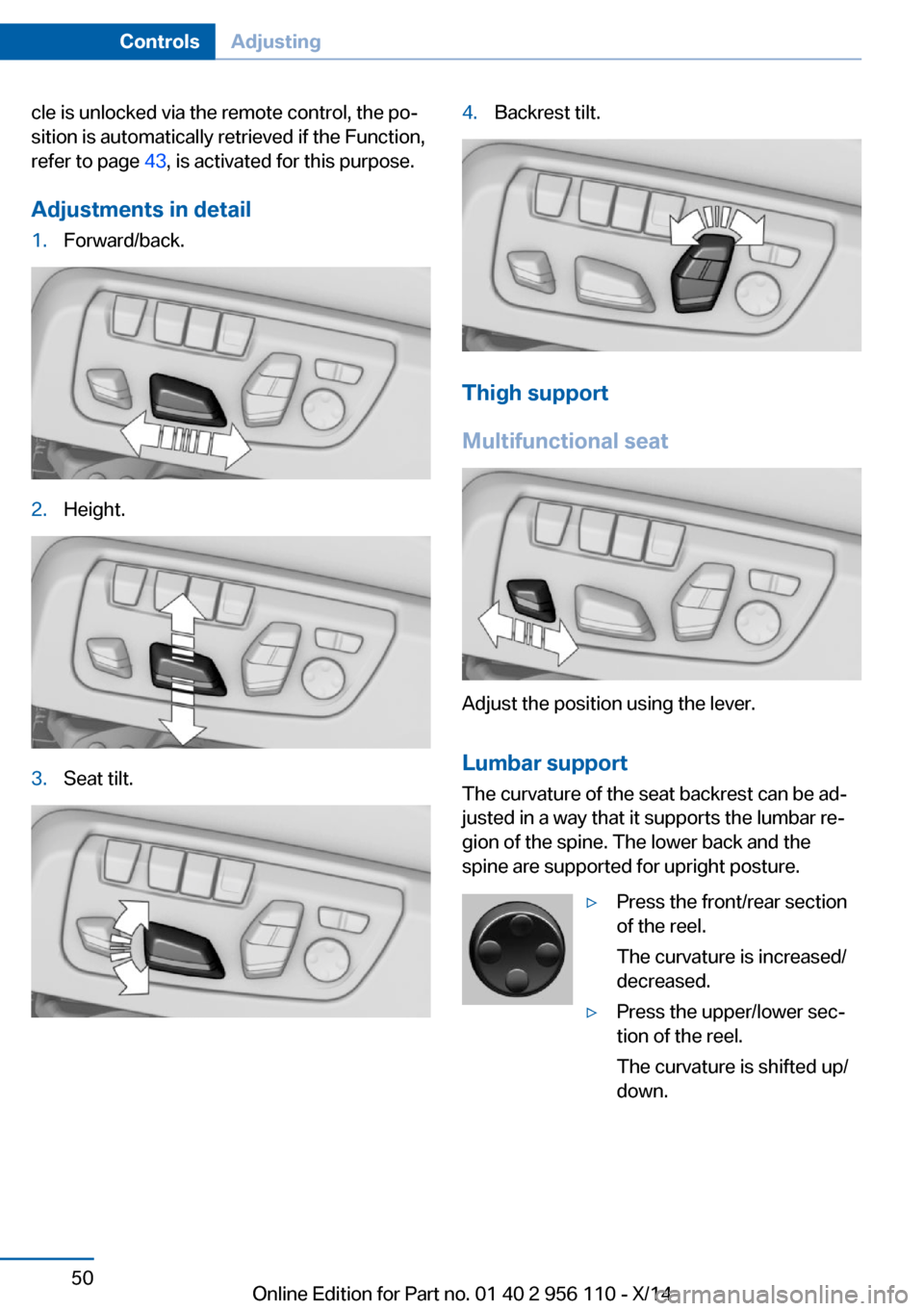
Adjustments in detail1.Forward/back.2.Height.3.Seat tilt.4.Backrest tilt.
Thigh support
Multifunctional seat
Adjust the position using the lever.
Lumbar support
The curvature of the seat backrest can be ad‐
justed in a way that it supports the lumbar re‐
gion of the spine. The lower back and the
spine are supported for upright posture.
▷Press the front/rear section
of the reel.
The curvature is increased/
decreased.▷Press the upper/lower sec‐
tion of the reel.
The curvature is shifted up/
down.Seite 50ControlsAdjusting50
Online Edition for Part no. 01 40 2 956 110 - X/14
Page 58 of 253
using the red button in the buckle. Fasten the
belt before continuing on your trip.
Damage to safety beltsWear and tear after accidents or when dam‐
aged otherwise:
Have the safety belts, including the safety belt
tensioners, replaced and have the belt anchors
checked.
Check and replace safety belts
This should only be done by your service
center; otherwise, this safety feature might not
work properly.◀
Headrests
Correctly adjusted head restraint General information A correctly adjusted head restraint reduces the
risk of injury to cervical vertebrae in the event
of an accident.
Note Adjusting the head restraint
Adjust the head restraints of all occupied
seats properly; otherwise, there is an increased
risk of injury in an accident.◀
Height
Adjust the head restraint so that its center is
approximately at ear level.
Distance
Adjust the distance so that the head restraint
is as close as possible to the back of the head.
Active head restraint In the event of a rear-end collision with a cer‐
tain severity, the active head restraint automat‐
ically reduces the distance from the head.Reduced protective function▷Do not use seat or head restraint
covers.▷Do not hang objects, e.g., clothes hangers,
on the head restraints.▷Only attach accessories approved by BMW
to the seat or head restraint.
Otherwise, the protective function of the active
head restraint will be impaired and the per‐
sonal safety of the occupants will be endan‐
gered.◀
Wear and tear after accidents or when dam‐
aged otherwise:
Have the active headrest checked and if
needed replaced.
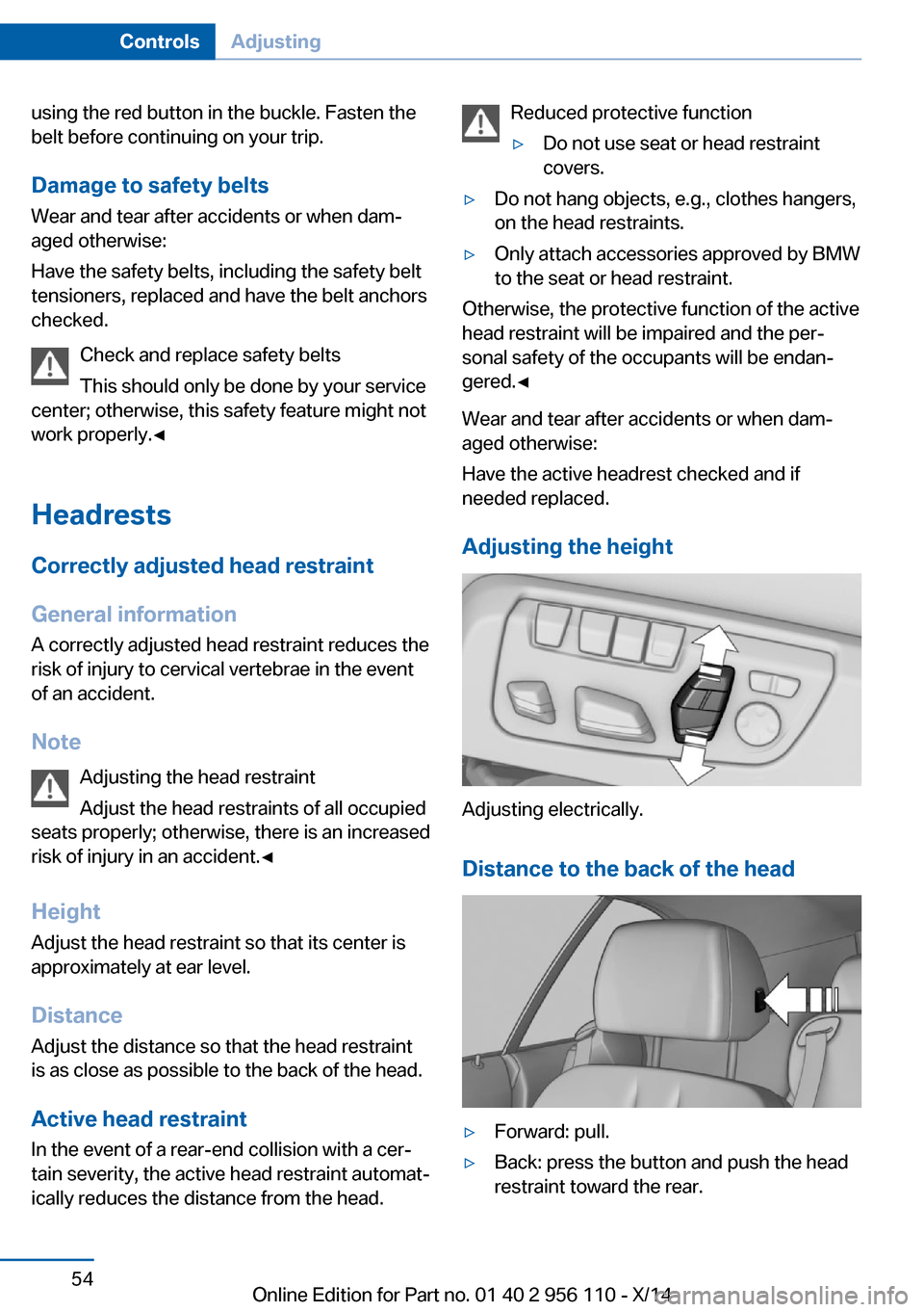
Adjusting the height
Adjusting electrically.
Distance to the back of the head
▷Forward: pull.▷Back: press the button and push the head
restraint toward the rear.Seite 54ControlsAdjusting54
Online Edition for Part no. 01 40 2 956 110 - X/14
Page 64 of 253
of unexpected movement of the rear seat
backrest.◀
On the front passenger seat
Deactivating airbags Deactivating the front-seat passenger
airbags
If a child restraint system is used in the front
passenger seat, deactivate the front-seat pas‐
senger airbags; otherwise, there is an in‐
creased risk of injury to the child when the air‐
bags are activated, even with a child restraint
system.◀
After installing a child restraint system in the
front passenger seat, make sure that the front,
knee and side airbags on the front passenger
side are deactivated.
Deactivate the front-seat passenger airbags
automatically, refer to page 103.
Seat position and height
Before installing a child restraint system, move
the front passenger seat as far back as possi‐
ble and adjust its height to the highest and
thus best possible position for the belt and to
offer optimal protection in the event of an acci‐
dent.
If the upper anchorage of the safety belt is lo‐
cated in front of the belt guide of the child seat,
move the passenger seat carefully forward un‐
til the best possible belt guide position is
reached.
Backrest width Backrest width for the child seat
Before installing a child restraint system
in the front passenger seat, the backrest width
must be opened completely. Do not change
the adjustment after this; otherwise, the stabil‐
ity of the child seat will be reduced.◀
Adjustable backrest width: before installing a
child restraint system in the front passengerseat, open the backrest width completely. Do
not change the backrest width again and do
not call up a memory position.
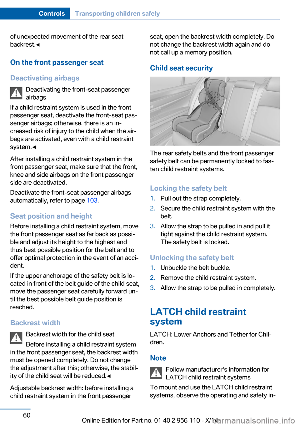
Child seat security
The rear safety belts and the front passenger
safety belt can be permanently locked to fas‐
ten child restraint systems.
Locking the safety belt
1.Pull out the strap completely.2.Secure the child restraint system with the
belt.3.Allow the strap to be pulled in and pull it
tight against the child restraint system.
The safety belt is locked.
Unlocking the safety belt
1.Unbuckle the belt buckle.2.Remove the child restraint system.3.Allow the strap to be pulled in completely.
LATCH child restraint
system
LATCH: Lower Anchors and Tether for Chil‐
dren.
Note Follow manufacturer's information for
LATCH child restraint systems
To mount and use the LATCH child restraint
systems, observe the operating and safety in‐
Seite 60ControlsTransporting children safely60
Online Edition for Part no. 01 40 2 956 110 - X/14
Page 98 of 253
▷Unfavorable light conditions.
If the image is distorted, check the basic set‐
tings.
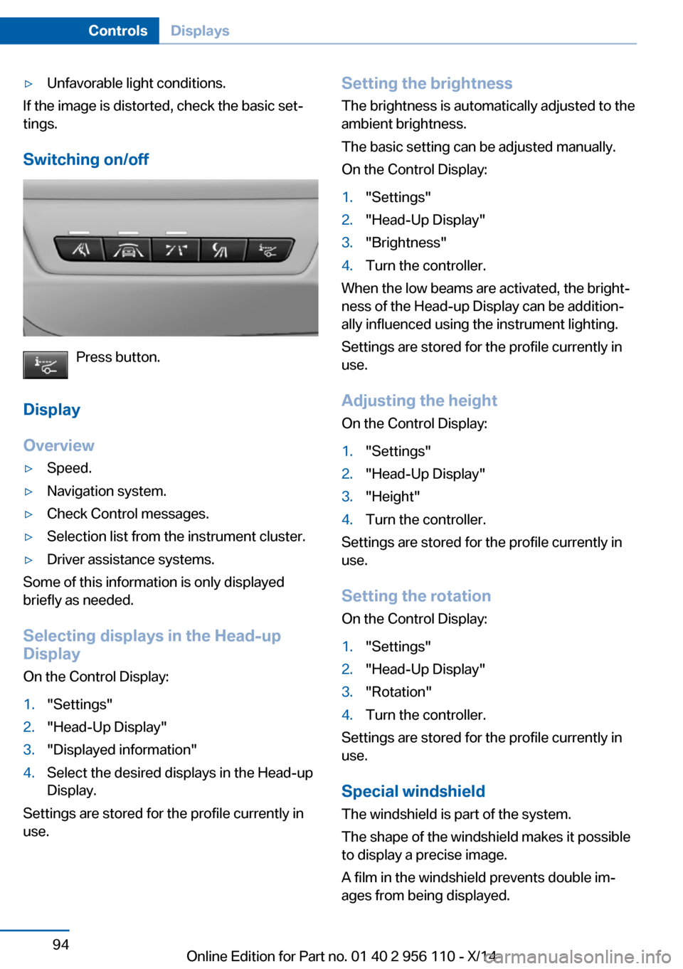
Switching on/off
Press button.
Display
Overview
▷Speed.▷Navigation system.▷Check Control messages.▷Selection list from the instrument cluster.▷Driver assistance systems.
Some of this information is only displayed
briefly as needed.
Selecting displays in the Head-up
Display
On the Control Display:
1."Settings"2."Head-Up Display"3."Displayed information"4.Select the desired displays in the Head-up
Display.
Settings are stored for the profile currently in
use.
Setting the brightness
The brightness is automatically adjusted to the
ambient brightness.
The basic setting can be adjusted manually.
On the Control Display:1."Settings"2."Head-Up Display"3."Brightness"4.Turn the controller.
When the low beams are activated, the bright‐
ness of the Head-up Display can be addition‐
ally influenced using the instrument lighting.
Settings are stored for the profile currently in
use.
Adjusting the height
On the Control Display:
1."Settings"2."Head-Up Display"3."Height"4.Turn the controller.
Settings are stored for the profile currently in
use.
Setting the rotation
On the Control Display:
1."Settings"2."Head-Up Display"3."Rotation"4.Turn the controller.
Settings are stored for the profile currently in
use.
Special windshield
The windshield is part of the system.
The shape of the windshield makes it possible
to display a precise image.
A film in the windshield prevents double im‐
ages from being displayed.
Seite 94ControlsDisplays94
Online Edition for Part no. 01 40 2 956 110 - X/14
Page 155 of 253
Switch the system back on if needed.
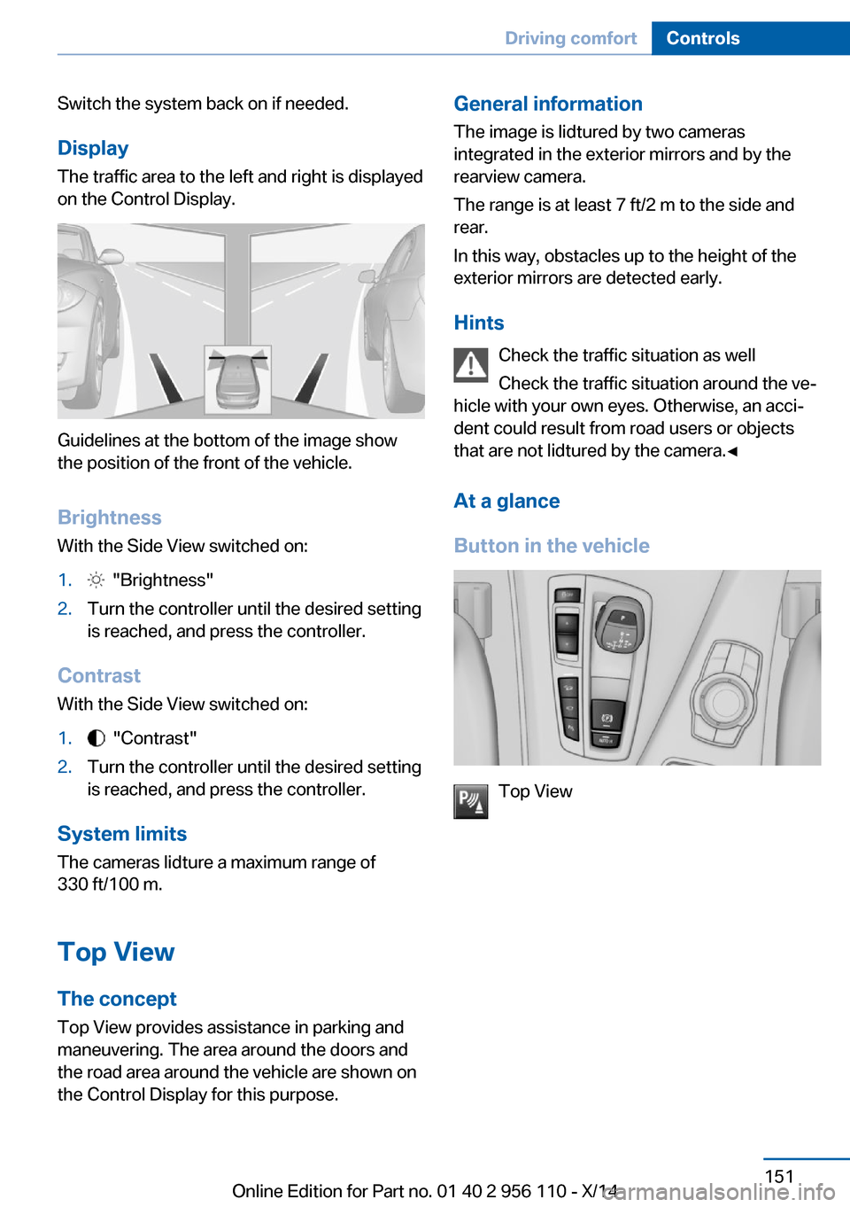
Display
The traffic area to the left and right is displayed
on the Control Display.
Guidelines at the bottom of the image show
the position of the front of the vehicle.
Brightness With the Side View switched on:
1. "Brightness"2.Turn the controller until the desired setting
is reached, and press the controller.
Contrast
With the Side View switched on:
1. "Contrast"2.Turn the controller until the desired setting
is reached, and press the controller.
System limits
The cameras lidture a maximum range of
330 ft/100 m.
Top View
The concept Top View provides assistance in parking and
maneuvering. The area around the doors and
the road area around the vehicle are shown on
the Control Display for this purpose.
General information
The image is lidtured by two cameras
integrated in the exterior mirrors and by the
rearview camera.
The range is at least 7 ft/2 m to the side and
rear.
In this way, obstacles up to the height of the
exterior mirrors are detected early.
Hints Check the traffic situation as well
Check the traffic situation around the ve‐
hicle with your own eyes. Otherwise, an acci‐
dent could result from road users or objects
that are not lidtured by the camera.◀
At a glance
Button in the vehicle
Top View
Seite 151Driving comfortControls151
Online Edition for Part no. 01 40 2 956 110 - X/14
Page 183 of 253
Do not remove the heat shields installed and
never apply undercoating to them. Make sure
that flammable materials, e. g. hay, leaves,
grass, etc. do not come in contact with the hot
exhaust system while driving, while in idle po‐
sition mode, or when parked. Such contact
could lead to a fire, resulting in an increased
risk of serious personal injury as well as prop‐
erty damage.
Do not touch hot exhaust pipes; otherwise,
there is a danger of getting burned.◀
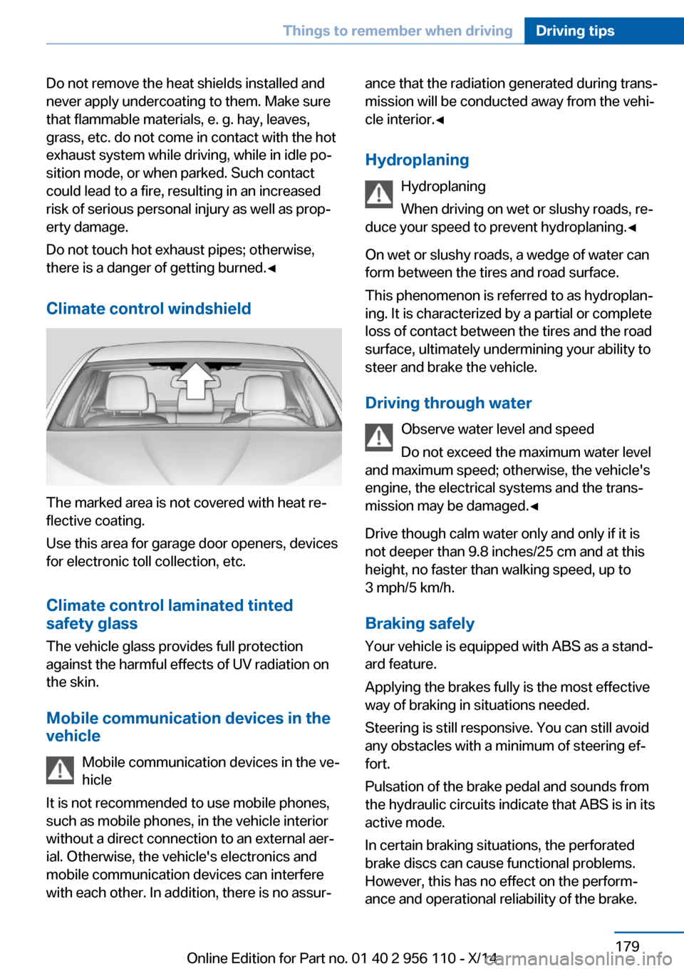
Climate control windshield
The marked area is not covered with heat re‐
flective coating.
Use this area for garage door openers, devices
for electronic toll collection, etc.
Climate control laminated tinted
safety glass
The vehicle glass provides full protection
against the harmful effects of UV radiation on
the skin.
Mobile communication devices in thevehicle
Mobile communication devices in the ve‐
hicle
It is not recommended to use mobile phones,
such as mobile phones, in the vehicle interior
without a direct connection to an external aer‐
ial. Otherwise, the vehicle's electronics and
mobile communication devices can interfere
with each other. In addition, there is no assur‐
ance that the radiation generated during trans‐
mission will be conducted away from the vehi‐
cle interior.◀
Hydroplaning Hydroplaning
When driving on wet or slushy roads, re‐
duce your speed to prevent hydroplaning.◀
On wet or slushy roads, a wedge of water can
form between the tires and road surface.
This phenomenon is referred to as hydroplan‐
ing. It is characterized by a partial or complete
loss of contact between the tires and the road
surface, ultimately undermining your ability to
steer and brake the vehicle.
Driving through water Observe water level and speed
Do not exceed the maximum water level
and maximum speed; otherwise, the vehicle's
engine, the electrical systems and the trans‐
mission may be damaged.◀
Drive though calm water only and only if it is
not deeper than 9.8 inches/25 cm and at this
height, no faster than walking speed, up to 3 mph/5 km/h.
Braking safely
Your vehicle is equipped with ABS as a stand‐
ard feature.
Applying the brakes fully is the most effective
way of braking in situations needed.
Steering is still responsive. You can still avoid
any obstacles with a minimum of steering ef‐
fort.
Pulsation of the brake pedal and sounds from
the hydraulic circuits indicate that ABS is in its
active mode.
In certain braking situations, the perforated
brake discs can cause functional problems.
However, this has no effect on the perform‐
ance and operational reliability of the brake.Seite 179Things to remember when drivingDriving tips179
Online Edition for Part no. 01 40 2 956 110 - X/14
Page 207 of 253
Traction
The traction grades, from highest to lowest,
are AA, A, B, and C.
Those grades represent the tire's ability to
stop on wet pavement as measured under
controlled conditions on specified government
test surfaces of asphalt and concrete. A tire
marked C may have poor traction performance.
The traction grade assigned to this tire is
based on straight-ahead braking traction tests,
and does not include acceleration, cornering,
hydroplaning, or peak traction characteristics.
Temperature
The temperature grades are A, the highest, B,
and C, representing the tire's resistance to the
generation of heat and its ability to dissipate
heat when tested under controlled conditions
on a specified indoor laboratory test wheel.
Sustained high temperature can cause the ma‐
terial of the tire to degenerate and reduce tire
life, and excessive temperature can lead to
sudden tire failure. The grade C corresponds
to a level of performance which all passenger
car tires must meet under the Federal Motor
Vehicle Safety Standard No. 109. Grades Band
A represent higher levels of performance on
the laboratory test wheel than the minimum re‐
quired by law.
Temperature grade for this tire
The temperature grade for this tire is es‐
tablished for a tire that is properly inflated and
not overloaded. Excessive speed, underinfla‐
tion, or excessive loading, either separately or
in combination, can cause heat buildup and
possible tire failure.
If necessary, have the vehicle towed.◀
RSC – Run-flat tires
Run-flat tires, refer to page 205, are labeled
with a circular symbol containing the letters
RSC marked on the sidewall.M+S
Winter and all-season tires with better cold
weather performance than summer tires.
Tire tread Summer tires
Do not drive with a tire tread depth of less than
0.12 in/3 mm.
There is an increased danger of hydroplaning if
the tire tread depth is less than 0.12 in/3 mm.
Winter tires
Do not drive with a tire tread depth of less than
0.16 in/4 mm.
Below a tread depth of 0.16 in/4 mm, tires are
less suitable for winter operation.
Minimum tread depth
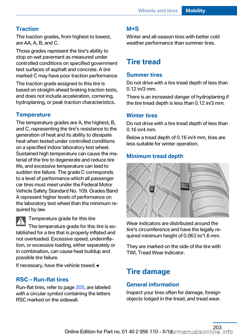
Wear indicators are distributed around the
tire's circumference and have the legally re‐
quired minimum height of 0.063 in/1.6 mm.
They are marked on the side of the tire with
TWI, Tread Wear Indicator.
Tire damage
General information
Inspect your tires often for damage, foreign
objects lodged in the tread, and tread wear.
Seite 203Wheels and tiresMobility203
Online Edition for Part no. 01 40 2 956 110 - X/14
Page 213 of 253
Never reach into the engine compart‐
ment
Never reach into spaces or gaps in the engine
compartment; otherwise, there is a risk of in‐
jury, e.g., from rotating or hot parts.◀
Danger of injury when the hood is open
There is a danger of injury from protrud‐
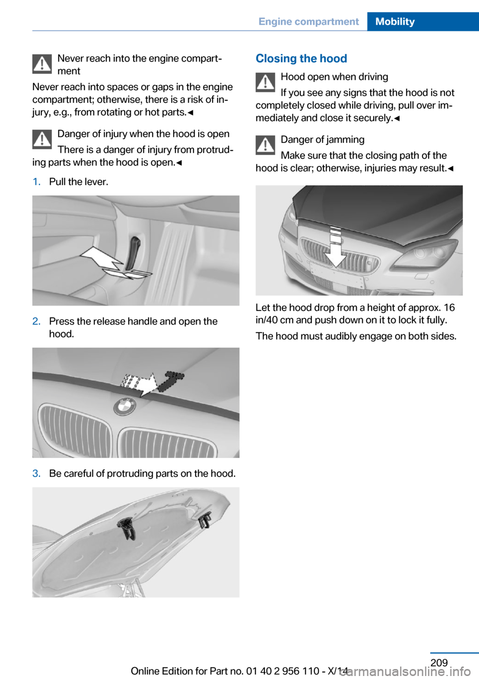
ing parts when the hood is open.◀1.Pull the lever.2.Press the release handle and open the
hood.3.Be careful of protruding parts on the hood.Closing the hood
Hood open when driving
If you see any signs that the hood is not
completely closed while driving, pull over im‐
mediately and close it securely.◀
Danger of jamming
Make sure that the closing path of the
hood is clear; otherwise, injuries may result.◀
Let the hood drop from a height of approx. 16
in/40 cm and push down on it to lock it fully.
The hood must audibly engage on both sides.
Seite 209Engine compartmentMobility209
Online Edition for Part no. 01 40 2 956 110 - X/14