lane assist BMW 6 SERIES GRAN COUPE 2016 F06 Owner's Manual
[x] Cancel search | Manufacturer: BMW, Model Year: 2016, Model line: 6 SERIES GRAN COUPE, Model: BMW 6 SERIES GRAN COUPE 2016 F06Pages: 255, PDF Size: 6.01 MB
Page 18 of 255
CockpitVehicle features and options
This chapter describes all standard, country-
specific and optional features offered with the
series. It also describes features that are not
necessarily available in your car, e. g., due tothe selected options or country versions. This
also applies to safety-related functions and
systems. The respectively applicable country
provisions must be observed when using the
respective features and systems.
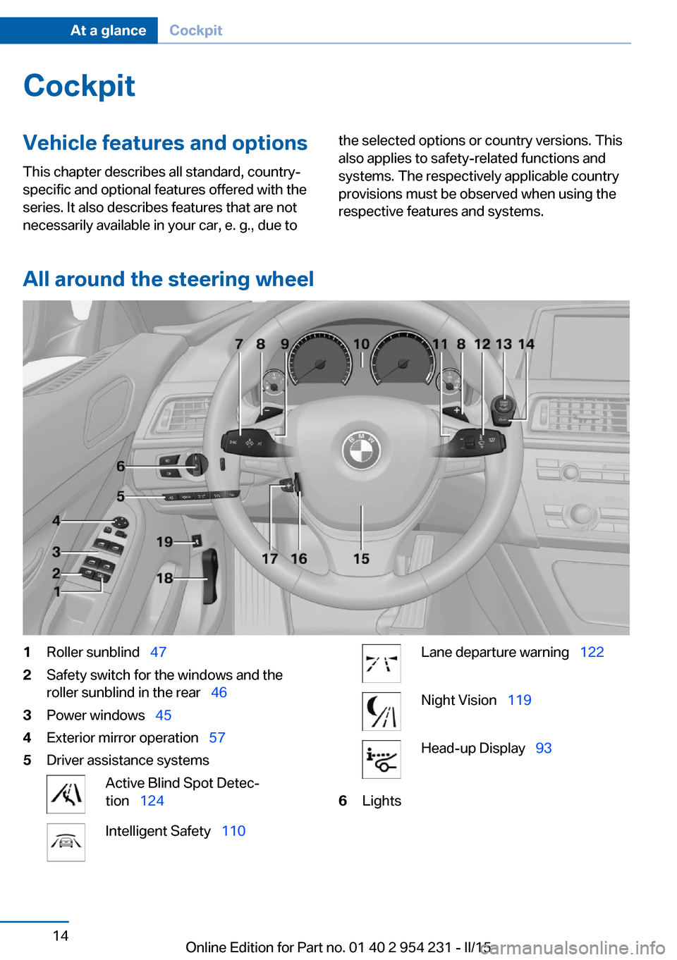
All around the steering wheel
1Roller sunblind 472Safety switch for the windows and the
roller sunblind in the rear 463Power windows 454Exterior mirror operation 575Driver assistance systemsActive Blind Spot Detec‐
tion 124Intelligent Safety 110Lane departure warning 122Night Vision 119Head-up Display 936LightsSeite 14At a glanceCockpit14
Online Edition for Part no. 01 40 2 954 231 - II/15
Page 87 of 255
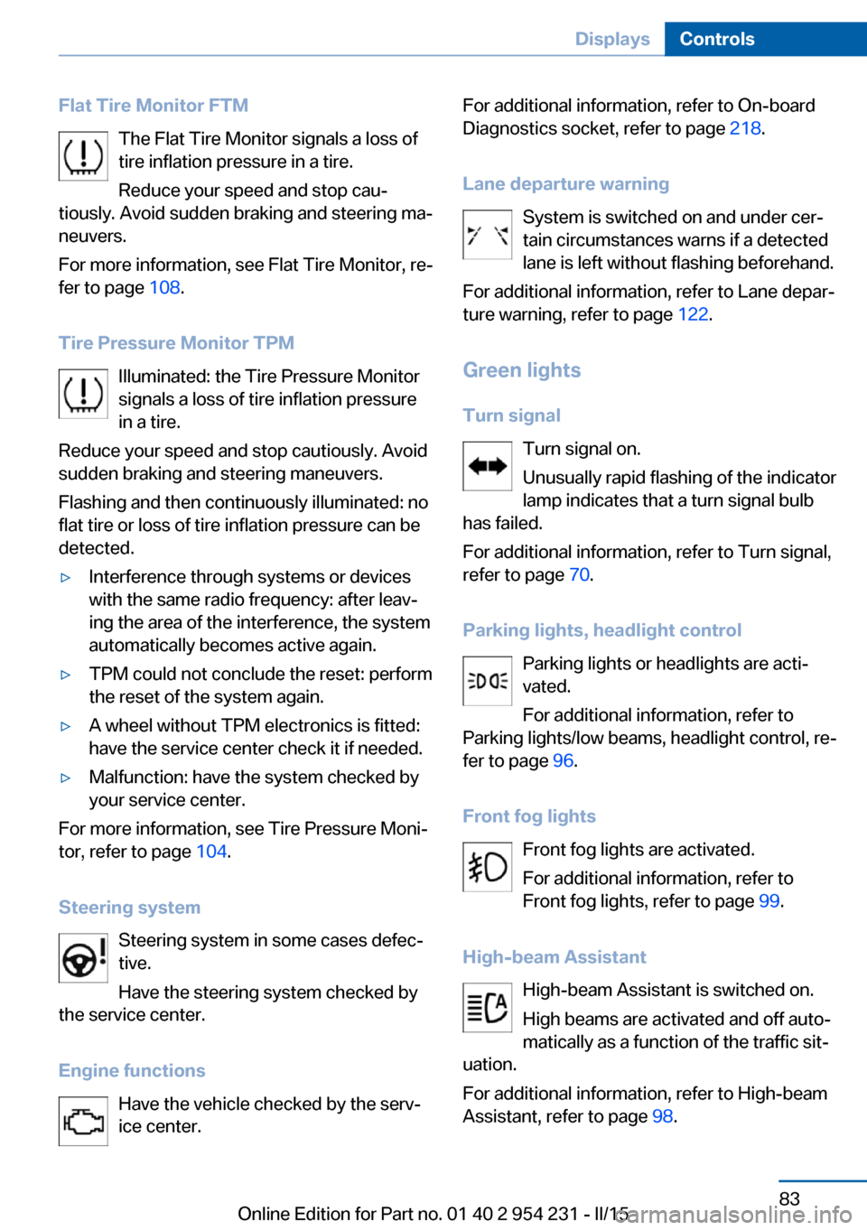
Flat Tire Monitor FTMThe Flat Tire Monitor signals a loss of
tire inflation pressure in a tire.
Reduce your speed and stop cau‐
tiously. Avoid sudden braking and steering ma‐
neuvers.
For more information, see Flat Tire Monitor, re‐
fer to page 108.
Tire Pressure Monitor TPM Illuminated: the Tire Pressure Monitor
signals a loss of tire inflation pressure
in a tire.
Reduce your speed and stop cautiously. Avoid
sudden braking and steering maneuvers.
Flashing and then continuously illuminated: no
flat tire or loss of tire inflation pressure can be
detected.▷Interference through systems or devices
with the same radio frequency: after leav‐
ing the area of the interference, the system
automatically becomes active again.▷TPM could not conclude the reset: perform
the reset of the system again.▷A wheel without TPM electronics is fitted:
have the service center check it if needed.▷Malfunction: have the system checked by
your service center.
For more information, see Tire Pressure Moni‐
tor, refer to page 104.
Steering system Steering system in some cases defec‐
tive.
Have the steering system checked by
the service center.
Engine functions Have the vehicle checked by the serv‐ice center.
For additional information, refer to On-board
Diagnostics socket, refer to page 218.
Lane departure warning System is switched on and under cer‐
tain circumstances warns if a detected
lane is left without flashing beforehand.
For additional information, refer to Lane depar‐
ture warning, refer to page 122.
Green lights Turn signal Turn signal on.
Unusually rapid flashing of the indicator
lamp indicates that a turn signal bulb
has failed.
For additional information, refer to Turn signal,
refer to page 70.
Parking lights, headlight control Parking lights or headlights are acti‐
vated.
For additional information, refer to
Parking lights/low beams, headlight control, re‐
fer to page 96.
Front fog lights Front fog lights are activated.
For additional information, refer to
Front fog lights, refer to page 99.
High-beam Assistant High-beam Assistant is switched on.
High beams are activated and off auto‐
matically as a function of the traffic sit‐
uation.
For additional information, refer to High-beam
Assistant, refer to page 98.Seite 83DisplaysControls83
Online Edition for Part no. 01 40 2 954 231 - II/15
Page 129 of 255
Display
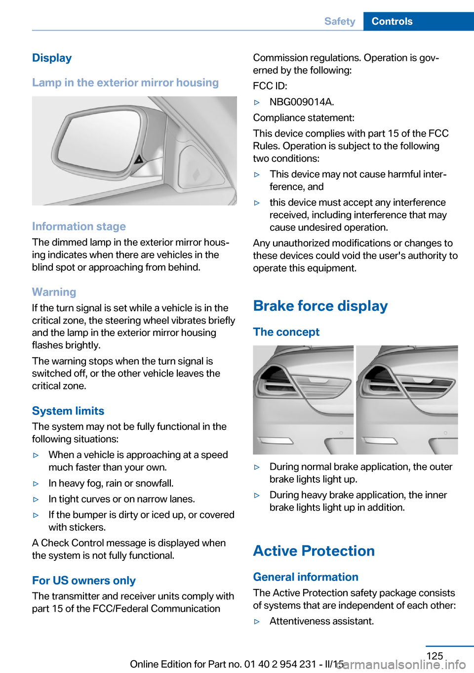
Lamp in the exterior mirror housing
Information stage
The dimmed lamp in the exterior mirror hous‐
ing indicates when there are vehicles in the
blind spot or approaching from behind.
Warning If the turn signal is set while a vehicle is in the
critical zone, the steering wheel vibrates briefly
and the lamp in the exterior mirror housing
flashes brightly.
The warning stops when the turn signal is
switched off, or the other vehicle leaves the
critical zone.
System limits
The system may not be fully functional in the
following situations:
▷When a vehicle is approaching at a speed
much faster than your own.▷In heavy fog, rain or snowfall.▷In tight curves or on narrow lanes.▷If the bumper is dirty or iced up, or covered
with stickers.
A Check Control message is displayed when
the system is not fully functional.
For US owners only The transmitter and receiver units comply with
part 15 of the FCC/Federal Communication
Commission regulations. Operation is gov‐
erned by the following:
FCC ID:▷NBG009014A.
Compliance statement:
This device complies with part 15 of the FCC
Rules. Operation is subject to the following
two conditions:
▷This device may not cause harmful inter‐
ference, and▷this device must accept any interference
received, including interference that may
cause undesired operation.
Any unauthorized modifications or changes to
these devices could void the user's authority to
operate this equipment.
Brake force display
The concept
▷During normal brake application, the outer
brake lights light up.▷During heavy brake application, the inner
brake lights light up in addition.
Active Protection
General information
The Active Protection safety package consists
of systems that are independent of each other:
▷Attentiveness assistant.Seite 125SafetyControls125
Online Edition for Part no. 01 40 2 954 231 - II/15
Page 130 of 255
▷PreCrash▷PostCrash
Attentiveness assistant
The concept The system can detect increasing lack of alert‐
ness or fatigue of the driver during long, mo‐
notonous journeys, e.g., on highways. In this situation, it is recommended that the driver
takes a break.
Note Personal responsibility
The system cannot act as a substitute for
the personal assessment of one's physical
state and may not detect an increasing lack of
alertness or fatigue or may not detect it cor‐
rectly. Therefore, make sure that the driver is
rested and alert; otherwise, risks may be de‐
tected too late and an accident be caused as a
result.◀
Function
The system is activated each time the engine
is started and cannot be switched off.
After travel has begun, the system is trained
about the driver, so that increasing lack of
alertness or fatigue can be detected.
This procedure takes the following criteria into
account:
▷Personal driving style, e.g., steering behav‐
ior.▷Driving conditions, e.g., length of trip.
Starting at approximately 43 mph/70 km/h, the
system is active and can display a recommen‐
dation to take a break.
Break recommendation
If the driver becomes increasingly less alert or
fatigued, a message is displayed in the Control
Display with the recommendation to take a
break.
A recommendation to take a break is displayed
only once during an uninterrupted trip.
After a break, another recommendation to take
a break cannot be displayed until after approxi‐
mately 45 minutes.
System limits
The function may be limited in the following
situations, for instance, and will either output
an incorrect warning or no warning at all:▷When the clock is set incorrectly.▷When the vehicle speed is mainly below
about 43 mph/70 km/h.▷With a sporty driving style, such as during
rapid acceleration or when cornering fast.▷In active driving situations, such as when
changing lanes frequently.▷When the road surface is poor.▷In the event of strong side winds.
PreCrash
The concept With this system critical driving situations that
might result in an accident can be detected
above a speed of approx. 20 mph/30 km/h. In these situations, preventive measures are au‐
tomatically taken to minimize the risk of an ac‐
cident as much as possible.
Critical driving situations may include:
Emergency stop.
If the vehicle includes the front-end collision
warning or front-end collision warning with
braking feature, impending collisions with vehi‐
cles driving ahead or stopped in front of you
can also be detected within the system's
range.
Seite 126ControlsSafety126
Online Edition for Part no. 01 40 2 954 231 - II/15
Page 152 of 255
Camera
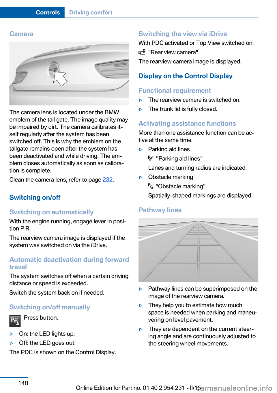
The camera lens is located under the BMW
emblem of the tail gate. The image quality may
be impaired by dirt. The camera calibrates it‐
self regularly after the system has been
switched off. This is why the emblem on the
tailgate remains open after the system has
been deactivated and while driving. The em‐
blem closes automatically as soon as calibra‐
tion is complete.
Clean the camera lens, refer to page 232.
Switching on/off
Switching on automatically With the engine running, engage lever in posi‐
tion P R.
The rearview camera image is displayed if the
system was switched on via the iDrive.
Automatic deactivation during forward
travel
The system switches off when a certain driving
distance or speed is exceeded.
Switch the system back on if needed.
Switching on/off manually Press button.
▷On: the LED lights up.▷Off: the LED goes out.
The PDC is shown on the Control Display.
Switching the view via iDriveWith PDC activated or Top View switched on:
"Rear view camera"
The rearview camera image is displayed.
Display on the Control Display
Functional requirement
▷The rearview camera is switched on.▷The trunk lid is fully closed.
Activating assistance functions
More than one assistance function can be ac‐
tive at the same time.
▷Parking aid lines
"Parking aid lines"
Lanes and turning radius are indicated.
▷Obstacle marking
"Obstacle marking"
Spatially-shaped markings are displayed.
Pathway lines
▷Pathway lines can be superimposed on the
image of the rearview camera.▷They help you to estimate how much
space is needed when parking and maneu‐
vering on level pavement.▷They are dependent on the current steer‐
ing angle and are continuously adjusted to
the steering wheel movements.Seite 148ControlsDriving comfort148
Online Edition for Part no. 01 40 2 954 231 - II/15
Page 156 of 255
Cameras
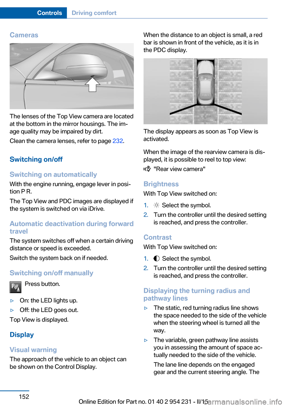
The lenses of the Top View camera are located
at the bottom in the mirror housings. The im‐
age quality may be impaired by dirt.
Clean the camera lenses, refer to page 232.
Switching on/off
Switching on automatically With the engine running, engage lever in posi‐
tion P R.
The Top View and PDC images are displayed if
the system is switched on via iDrive.
Automatic deactivation during forward
travel
The system switches off when a certain driving
distance or speed is exceeded.
Switch the system back on if needed.
Switching on/off manually Press button.
▷On: the LED lights up.▷Off: the LED goes out.
Top View is displayed.
Display
Visual warning
The approach of the vehicle to an object can
be shown on the Control Display.
When the distance to an object is small, a red
bar is shown in front of the vehicle, as it is in
the PDC display.
The display appears as soon as Top View is
activated.
When the image of the rearview camera is dis‐
played, it is possible to reel to top view:
"Rear view camera"
Brightness
With Top View switched on:
1. Select the symbol.2.Turn the controller until the desired setting
is reached, and press the controller.
Contrast
With Top View switched on:
1. Select the symbol.2.Turn the controller until the desired setting
is reached, and press the controller.
Displaying the turning radius and
pathway lines
▷The static, red turning radius line shows
the space needed to the side of the vehicle
when the steering wheel is turned all the
way.▷The variable, green pathway line assists
you in assessing the amount of space ac‐
tually needed to the side of the vehicle.
The lane line depends on the engaged
gear and the current steering angle. TheSeite 152ControlsDriving comfort152
Online Edition for Part no. 01 40 2 954 231 - II/15
Page 248 of 255
Hand-held transmitter, alter‐nating code 166
Hazard warning flashers 224
HDC Hill Descent Con‐ trol 130
Head airbags 101
Headlight control, auto‐ matic 97
Headlight courtesy delay fea‐ ture 97
Headlight courtesy delay fea‐ ture via remote control 38
Headlight flasher 70
Headlight glass 220
Headlights 219
Headlights, care 230
Headlight washer system 71
Head restraints 50
Head restraints, front 55
Head-up Display 93
Head-up Display, care 232
Heating, refer to Parked-car heating 162
Heavy cargo, stowing 182
Height, seats 50
Height, vehicle 236
High-beam Assistant 98
High beams 70
High beams/low beams, refer to High-beam Assistant 98
Hill Descent Control HDC 130
Hills 180
Hill start assistant, refer to Drive-off assistant 128
Hints 6
Holder for beverages 174
Homepage 6
Hood 210
Horn 14
Hotel function, trunk lid 41
Hot exhaust system 178
HUD Head-up Display 93
Hydroplaning 179 I
Ice warning, see External temperature warning 85
Icy roads, see External tem‐ perature warning 85
Identification marks, tires 202
Identification number, see ve‐ hicle identification num‐
ber 9
iDrive 18
Ignition key, refer to Remote control 34
Ignition off 64
Ignition on 64
Indication of a flat tire 105 , 108
Indicator and alarm lamps, see Check Control 81
Indicator lamp, see Check Control 81
Individual air distribution 158
Individual settings, refer to Personal Profile 35
Inflation pressure, tires 196
Inflation pressure warning FTM, tires 108
Info display, refer to On- Board computer 90
Initialization, Integral Active Steering 132
Initialize, Tire Pressure Moni‐ tor TPM 105
Initializing, Flat Tire Monitor FTM 108
Instrument cluster 77
Instrument cluster, electronic displays 77
Instrument display, multifunc‐ tional 78
Instrument lighting 99
Integral Active Steering 132
Integrated key 34
Integrated Owner's Manual in the vehicle 29 Intelligent Emergency Re‐
quest 224
Intelligent Safety 110
Intensity, AUTO pro‐ gram 158
Interior equipment 165
Interior lights 99
Interior lights during unlock‐ ing 37
Interior lights with the vehicle locked 38
Interior motion sensor 45
Interior rearview mirror, auto‐ matic dimming feature 58
Internet page 6
Interval display, service re‐ quirements 87
Interval mode 71
J
Jacking points for the vehicle jack 222
Joystick, Steptronic transmis‐ sion 74
Jump-starting 225
K
Key/remote control 34
Keyless Go, refer to Comfort Access 41
Key Memory, refer to Per‐ sonal Profile 35
Kickdown, Steptronic trans‐ mission 74
Knee airbag 102
L Lamp replacement, front 219
Lamp replacement, rear 221
Lane departure warning 122
Lane margin, warning 122
Language on Control Dis‐ play 93 Seite 244ReferenceEverything from A to Z244
Online Edition for Part no. 01 40 2 954 231 - II/15