height BMW 6 SERIES GRAN COUPE 2017 Owners Manual
[x] Cancel search | Manufacturer: BMW, Model Year: 2017, Model line: 6 SERIES GRAN COUPE, Model: BMW 6 SERIES GRAN COUPE 2017Pages: 261, PDF Size: 5.24 MB
Page 51 of 261
AdjustingVehicle features and options
This chapter describes all standard, country-
specific and optional features offered with the
series. It also describes features that are not
necessarily available in your car, e. g., due to
the selected options or country versions. This
also applies to safety-related functions and
systems. The respectively applicable country
provisions must be observed when using the
respective features and systems.
Sitting safely The ideal seating position meeting the needs
of the occupants can make a vital contribution
to relaxed, fatigue-free driving.
The seating position plays an important role in
an accident in combination with:▷Safety belts, refer to page 55.▷Head restraints, refer to page 56.▷Airbags.
Seats
Information WARNING
Seat adjustments while driving can lead
to unexpected movements of the seat. Vehicle
control could be lost. There is risk of an acci‐
dent. Only adjust the seat on the driver's side
when the vehicle is stationary.◀
WARNING
With a backrest inclined too far to the
rear, the protective effect of the safety belt
cannot be ensured anymore. There is a danger
of sliding under the safety belt in an accident.
There is a risk of injury or danger to life. Adjust
the seat prior to starting the trip. Adjust the
backrest so that it is in the most upright posi‐
tion as possible and do not adjust again while
driving.◀
WARNING
There is risk of jamming when moving
the seats. There is a risk of injury or risk of
property damage. Make sure that the area of
movement of the seat is clear prior to any ad‐
justment.◀
Middle seat The 6 Series Gran Coupe is designed as a
4+1-seater vehicle.
The middle seat is of limited usefulness. It is
recommended that this seat only be used by
persons who can use the backrest as a substi‐ tute for the head restraint.
Adjusting the head restraints, refer to
page 56.
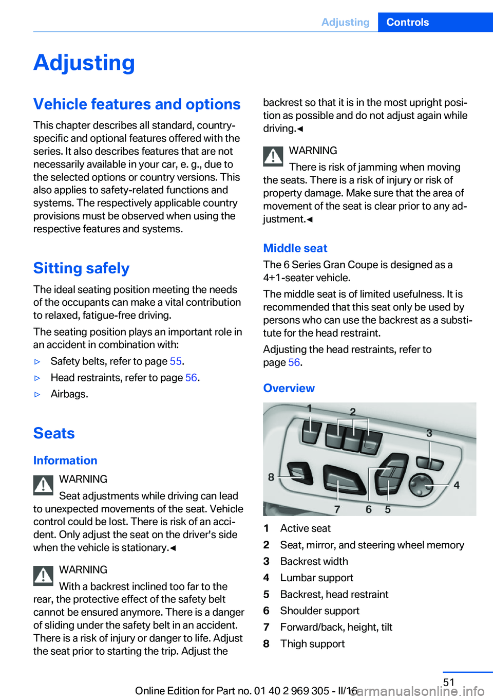
Overview1Active seat2Seat, mirror, and steering wheel memory3Backrest width4Lumbar support5Backrest, head restraint6Shoulder support7Forward/back, height, tilt8Thigh supportSeite 51AdjustingControls51
Online Edition for Part no. 01 40 2 969 305 - II/16
Page 52 of 261
General information
The seat setting for the driver's seat is stored
for the profile currently used. When the vehicle
is unlocked via the remote control, the position
is automatically retrieved if the Function is acti‐
vated for this purpose.
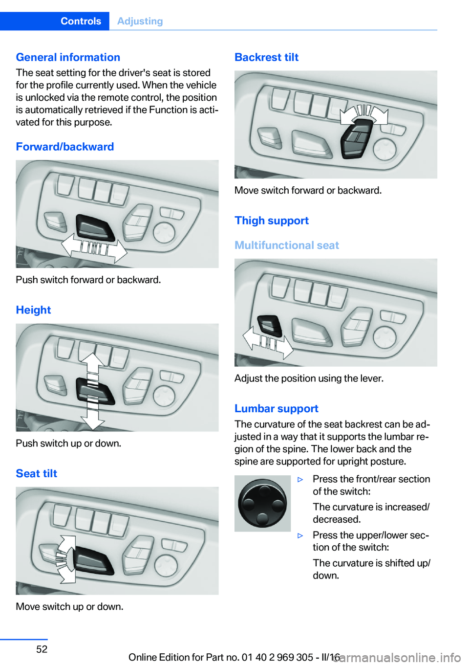
Forward/backward
Push switch forward or backward.
Height
Push switch up or down. Seat tilt
Move switch up or down.
Backrest tilt
Move switch forward or backward.Thigh support
Multifunctional seat
Adjust the position using the lever.
Lumbar support
The curvature of the seat backrest can be ad‐
justed in a way that it supports the lumbar re‐
gion of the spine. The lower back and the
spine are supported for upright posture.
▷Press the front/rear section
of the switch:
The curvature is increased/
decreased.▷Press the upper/lower sec‐
tion of the switch:
The curvature is shifted up/
down.Seite 52ControlsAdjusting52
Online Edition for Part no. 01 40 2 969 305 - II/16
Page 56 of 261
Unbuckling the safety belt1.Hold the safety belt firmly.2.Press the red button in the belt buckle.3.Guide the safety belt back into its roll-up
mechanism.
Safety belt reminder for driver's and
passenger's seat
The indicator lamp lights up and a sig‐
nal sounds. Make sure that the safety
belts are positioned correctly. The
safety belt reminder is active at speeds above
approx. 6 mph/10 km/h. It can also be activated
if objects are placed on the front passenger
seat.
Safety mode In critical situations, for example during an
emergency stop, the front safety belts tighten
automatically.
If the situation passes without an accident oc‐
curring, the belt tension relaxes.
If the belt tension does not loosen automati‐
cally, stop the vehicle and unbuckle the safety
belt using the red button in the buckle. Fasten
the safety belt before continuing on your trip.
Damage to safety belts WARNING
The protective effect of the safety belts
may not be fully functional or fail in the follow‐
ing situations:
▷Safety belts are damaged, soiled or
changed in any other way.▷Safety belt buckle is damaged or heavily
soiled.▷Belt tensioners or belt retractors were
modified.
Safety belts can be imperceptibly damaged in
the event of an accident. There is a risk of in‐
jury or danger to life. Do not modify safety
belts, safety belt buckles, belt tensioners, belt
retractors or belt anchors and keep them
clean. Have the safety belts checked after an
accident at the dealer’s service center or an‐
other qualified service center or repair shop.◀
Headrests Information WARNING
A missing protective effect due to re‐
moved or not correctly adjusted head re‐
straints can cause injuries in the head and
neck area. There is a a risk of injury. Install
head restraints on occupied seats prior to driv‐
ing and make sure that the center of the head
restraint supports the back of the head at eye
level.◀
WARNING
Objects on the head restraint reduce the
protective effect in the head and neck area.
There is a a risk of injury.▷Do not use seat or head restraint covers.▷Do not hang objects, e.g., clothes hangers,
directly on the head restraint.▷Only use accessories that have been de‐
termined to be safe for attachment to a
head restraint.▷Do not use any accessories, e.g., pillows,
while driving.◀
Correctly adjusted head restraint
General information
A correctly adjusted head restraint reduces the
risk of injury to cervical vertebrae in the event
of an accident.
Height Adjust the head restraint so that its center is
approximately at eye level.
Seite 56ControlsAdjusting56
Online Edition for Part no. 01 40 2 969 305 - II/16
Page 57 of 261
Distance
Adjust the distance so that the head restraint is as close as possible to the back of the head.
Active head restraint
In the event of a rear-end collision with a cer‐
tain severity, the active head restraint automat‐
ically reduces the distance from the head.
Wear and tear after accidents or when dam‐
aged otherwise:
Have the active head restraint checked and if
needed replaced.
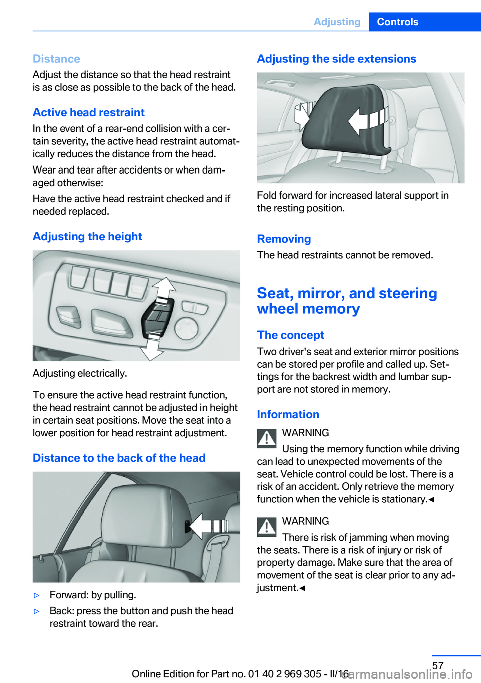
Adjusting the height
Adjusting electrically.
To ensure the active head restraint function,
the head restraint cannot be adjusted in height
in certain seat positions. Move the seat into a
lower position for head restraint adjustment.
Distance to the back of the head
▷Forward: by pulling.▷Back: press the button and push the head
restraint toward the rear.Adjusting the side extensions
Fold forward for increased lateral support in
the resting position.
Removing The head restraints cannot be removed.
Seat, mirror, and steering
wheel memory
The concept
Two driver's seat and exterior mirror positions
can be stored per profile and called up. Set‐
tings for the backrest width and lumbar sup‐
port are not stored in memory.
Information WARNING
Using the memory function while driving
can lead to unexpected movements of the
seat. Vehicle control could be lost. There is a
risk of an accident. Only retrieve the memory function when the vehicle is stationary.◀
WARNING
There is risk of jamming when moving
the seats. There is a risk of injury or risk of
property damage. Make sure that the area of
movement of the seat is clear prior to any ad‐ justment.◀
Seite 57AdjustingControls57
Online Edition for Part no. 01 40 2 969 305 - II/16
Page 63 of 261
WARNING
The stability of the child restraint system
is limited or compromised with incorrect seat
adjustment or improper installation of the child
seat. There is a risk of injury or danger to life.
Make sure that the child restraint system fits
securely against the backrest. If possible, ad‐
just the backrest tilt for all affected backrests
and correctly adjust the seats. Make sure that
seats and backrests are securely engaged. If
possible, adjust the height of the head re‐
straints or remove them.◀
Installing child restraint
systems
Information Pay attention to the specifications of the child
restraint system manufacturer when selecting,
installing, and using child restraint systems.
WARNING
The stability of the child restraint system
is limited or compromised with incorrect seat
adjustment or improper installation of the child
seat. There is a risk of injury or danger to life.
Make sure that the child restraint system fits
securely against the backrest. If possible, ad‐
just the backrest tilt for all affected backrests
and correctly adjust the seats. Make sure that
seats and backrests are securely engaged. If
possible, adjust the height of the head re‐
straints or remove them.◀
On the front passenger seat
Deactivating airbags WARNING
Active front-seat passenger airbags can
injure a child in a child restraint system when
the airbags are activated. There is a risk of in‐
jury. Make sure that the front-seat passengerairbags are deactivated and that the PASSEN‐
GER AIRBAG OFF indicator lamp lights up.◀
After installing a child restraint system in the
front passenger seat, make sure that the front,
knee and side airbags on the front passenger
side are deactivated.
Deactivate the front-seat passenger airbags
automatically, refer to page 107.
Seat position and height
Before installing a child restraint system, move
the front passenger seat as far back as possi‐
ble and bring it as far up as possible to obtain
the best possible position for the belt and to
offer optimal protection in the event of an acci‐
dent.
If the upper anchorage of the safety belt is lo‐
cated in front of the belt guide of the child seat,
move the passenger seat carefully forward un‐
til the best possible belt guide position is
reached.
Backrest width Adjustable backrest width: before installing a
child restraint system in the front passenger
seat, open the backrest width completely. Do
not change the backrest width again and do
not call up a memory position.
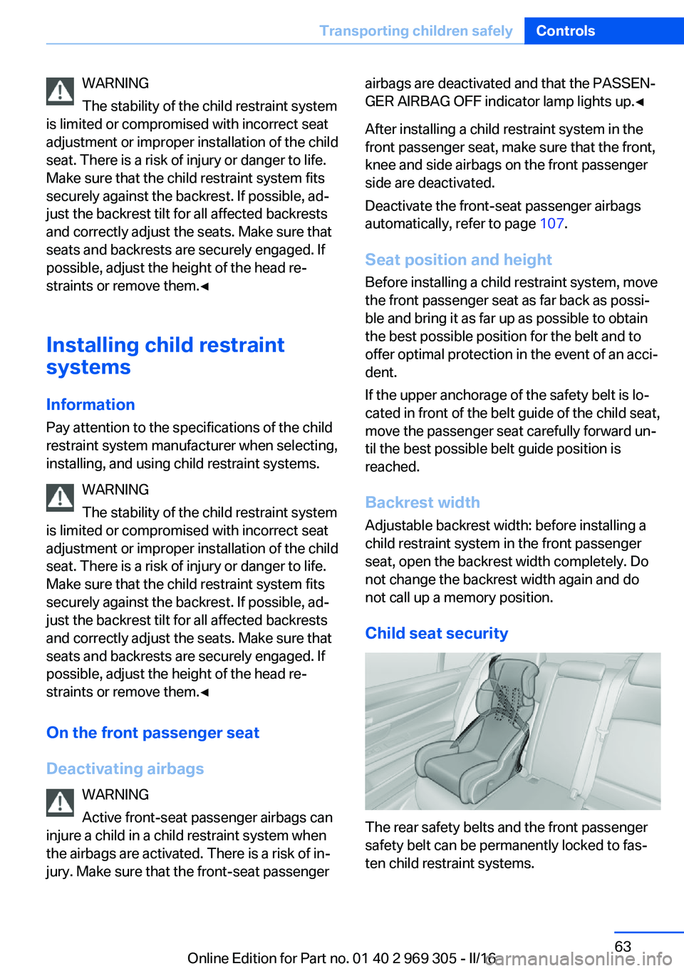
Child seat security
The rear safety belts and the front passenger
safety belt can be permanently locked to fas‐
ten child restraint systems.
Seite 63Transporting children safelyControls63
Online Edition for Part no. 01 40 2 969 305 - II/16
Page 99 of 261

On the Control Display:1."Settings"2."Head-Up Display"3."Brightness"4.Turn the Controller until the desired bright‐
ness is set.5.Press the Controller.
When the low beams are activated, the bright‐
ness of the Head-up Display can be addition‐
ally influenced using the instrument lighting.
Settings are stored for the profile currently
used.
Adjusting the height
On the Control Display:
1."Settings"2."Head-Up Display"3."Height"4.Turn the Controller until the desired height
is reached.5.Press the Controller.
Settings are stored for the profile currently
used.
Setting the rotation
The screen of the Head-up Display can be ro‐
tated around its own axis.
On the Control Display:
1."Settings"2."Head-Up Display"3."Rotation"4.Turn the Controller until the desired set‐
ting is selected.5.Press the Controller.
Settings are stored for the profile currently
used.
Special windshield
The windshield is part of the system.
The shape of the windshield makes it possible
to display a precise image.
A film in the windshield prevents double im‐
ages from being displayed.
For this reason, it is strongly suggested to
have the special windshield replaced by a
dealer’s service center or another qualified
service center or repair shop.Seite 99DisplaysControls99
Online Edition for Part no. 01 40 2 969 305 - II/16
Page 156 of 261
Clean the camera lenses, refer to page 242.
Switching on/off
Switching on/off manually Press button.
Automatic deactivation during forward
travel
The system switches off when a certain driving
distance or speed is exceeded.
Switch the system back on if needed.
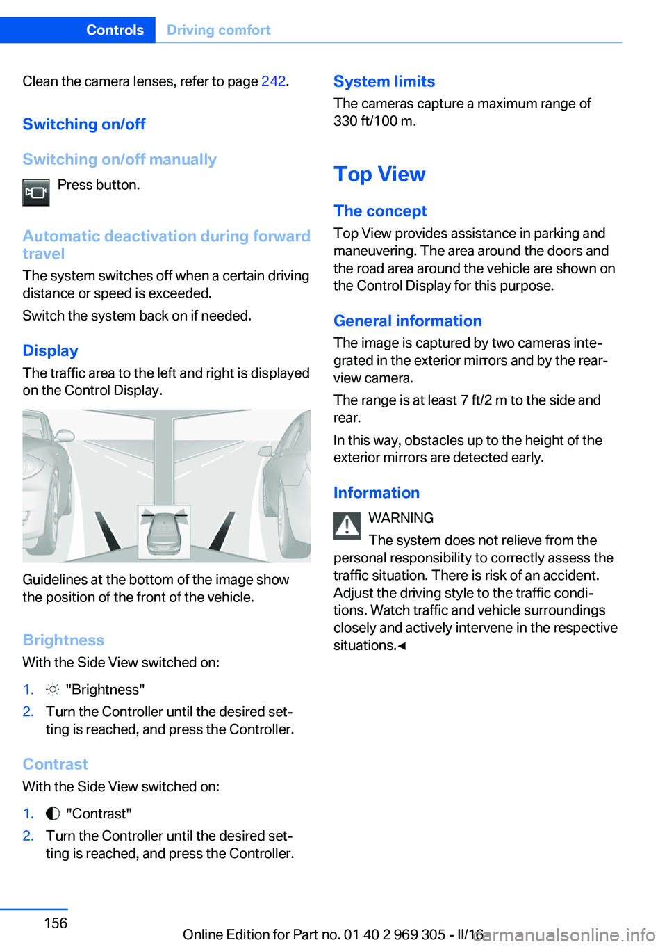
Display
The traffic area to the left and right is displayed
on the Control Display.
Guidelines at the bottom of the image show
the position of the front of the vehicle.
Brightness With the Side View switched on:
1. "Brightness"2.Turn the Controller until the desired set‐
ting is reached, and press the Controller.
Contrast
With the Side View switched on:
1. "Contrast"2.Turn the Controller until the desired set‐
ting is reached, and press the Controller.System limits
The cameras capture a maximum range of
330 ft/100 m.
Top View
The concept Top View provides assistance in parking and
maneuvering. The area around the doors and
the road area around the vehicle are shown on
the Control Display for this purpose.
General information
The image is captured by two cameras inte‐
grated in the exterior mirrors and by the rear‐
view camera.
The range is at least 7 ft/2 m to the side and
rear.
In this way, obstacles up to the height of the
exterior mirrors are detected early.
Information WARNING
The system does not relieve from the
personal responsibility to correctly assess the
traffic situation. There is risk of an accident.
Adjust the driving style to the traffic condi‐
tions. Watch traffic and vehicle surroundings
closely and actively intervene in the respective
situations.◀Seite 156ControlsDriving comfort156
Online Edition for Part no. 01 40 2 969 305 - II/16
Page 174 of 261
▷MTP devices.▷Devices such as fans or lights.
Overview
The USB interface and the AUX-IN port are lo‐
cated in the center armrest.
Through-loading system The concept The cargo area can be enlarged by folding
down the rear seat backrest.
The rear seat backrest is divided into two parts
at a ratio of 60 to 40.
The sides can be folded down separately or to‐
gether.
Information WARNING
Danger of jamming with folding down the
backrests. There is a risk of injuries or a risk of
property damage. Make sure that the area of
movement of the rear backrest and the of the
head restraint is clear prior to folding down.◀
WARNING
The stability of the child restraint system
is limited or compromised with incorrect seat
adjustment or improper installation of the child
seat. There is a risk of injury or danger to life.
Make sure that the child restraint system fits
securely against the backrest. If possible, ad‐
just the backrest tilt for all affected backrests
and correctly adjust the seats. Make sure that
seats and backrests are securely engaged. If
possible, adjust the height of the head re‐
straints or remove them.◀
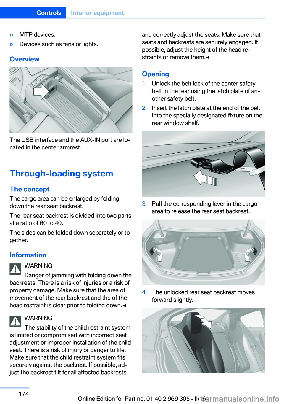
Opening1.Unlock the belt lock of the center safety
belt in the rear using the latch plate of an‐
other safety belt.2.Insert the latch plate at the end of the belt
into the specially designated fixture on the
rear window shelf.3.Pull the corresponding lever in the cargo
area to release the rear seat backrest.4.The unlocked rear seat backrest moves
forward slightly.Seite 174ControlsInterior equipment174
Online Edition for Part no. 01 40 2 969 305 - II/16
Page 209 of 261
cantly from the norm due to variations in driv‐
ing habits, service practices and differences in
road characteristics and climate.
Traction
The traction grades, from highest to lowest,
are AA, A, B, and C.
Those grades represent the tire's ability to
stop on wet pavement as measured under
controlled conditions on specified government
test surfaces of asphalt and concrete. A tire
marked C may have poor traction performance.
The traction grade assigned to this tire is
based on straight-ahead braking traction tests,
and does not include acceleration, cornering,
hydroplaning, or peak traction characteristics.
Temperature
The temperature grades are A, the highest, B, and C, representing the tire's resistance to the
generation of heat and its ability to dissipate
heat when tested under controlled conditions
on a specified indoor laboratory test wheel.
Sustained high temperature can cause the ma‐
terial of the tire to degenerate and reduce tire
life, and excessive temperature can lead to
sudden tire failure. The grade C corresponds
to a level of performance which all passenger
car tires must meet under the Federal Motor
Vehicle Safety Standard No. 109. Grades Band
A represent higher levels of performance on
the laboratory test wheel than the minimum re‐
quired by law.
WARNING
The temperature grade for this tire is es‐
tablished for a tire that is properly inflated and
not overloaded. Excessive speed, underinfla‐
tion, or excessive loading, either separately or
in combination, can cause heat buildup and
possible tire failure.◀RSC – Run-flat tires
Run-flat tires, refer to page 212, are labeled
with a circular symbol containing the letters
RSC marked on the sidewall.
M+S Winter and all-season tires with better cold
weather performance than summer tires.
Tire tread Summer tires
Do not drive with a tire tread depth of less than
0.12 inches/3 mm.
There is an increased danger of hydroplaning if
the tire tread depth is less than 0.12 in‐
ches/3 mm.
Winter tires
Do not drive with a tire tread depth of less than
0.16 inches/4 mm.
Below a tread depth of 0.16 inches/4 mm, tires
are less suitable for winter operation.
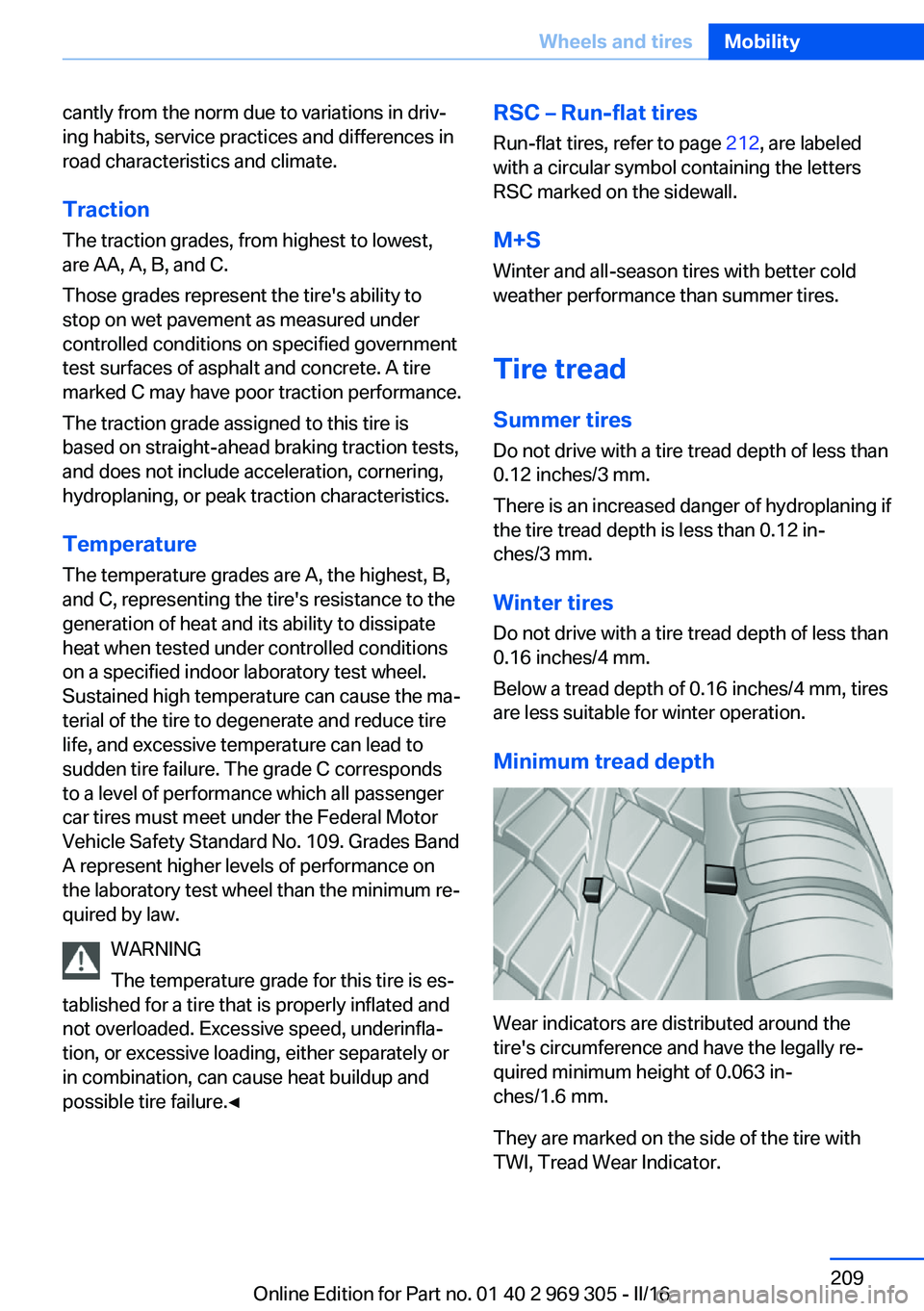
Minimum tread depth
Wear indicators are distributed around the
tire's circumference and have the legally re‐
quired minimum height of 0.063 in‐
ches/1.6 mm.
They are marked on the side of the tire with
TWI, Tread Wear Indicator.
Seite 209Wheels and tiresMobility209
Online Edition for Part no. 01 40 2 969 305 - II/16
Page 219 of 261
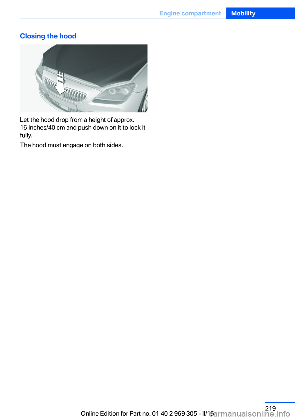
Closing the hood
Let the hood drop from a height of approx.
16 inches/40 cm and push down on it to lock it
fully.
The hood must engage on both sides.
Seite 219Engine compartmentMobility219
Online Edition for Part no. 01 40 2 969 305 - II/16