turn signal BMW 6 SERIES GRAN COUPE 2017 Owners Manual
[x] Cancel search | Manufacturer: BMW, Model Year: 2017, Model line: 6 SERIES GRAN COUPE, Model: BMW 6 SERIES GRAN COUPE 2017Pages: 261, PDF Size: 5.24 MB
Page 15 of 261
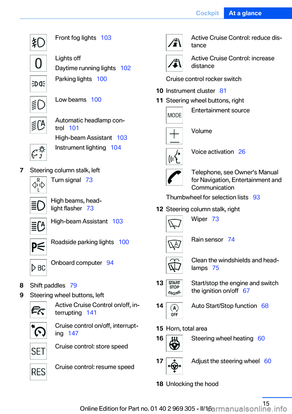
Front fog lights 103Lights off
Daytime running lights 102Parking lights 100Low beams 100Automatic headlamp con‐
trol 101
High-beam Assistant 103Instrument lighting 1047Steering column stalk, leftTurn signal 73High beams, head‐
light flasher 73High-beam Assistant 103Roadside parking lights 100Onboard computer 948Shift paddles 799Steering wheel buttons, leftActive Cruise Control on/off, in‐
terrupting 141Cruise control on/off, interrupt‐
ing 147Cruise control: store speedCruise control: resume speedActive Cruise Control: reduce dis‐
tanceActive Cruise Control: increase
distanceCruise control rocker switch10Instrument cluster 8111Steering wheel buttons, rightEntertainment sourceVolumeVoice activation 26Telephone, see Owner's Manual
for Navigation, Entertainment and
CommunicationThumbwheel for selection lists 9312Steering column stalk, rightWiper 73Rain sensor 74Clean the windshields and head‐
lamps 7513Start/stop the engine and switch
the ignition on/off 6714Auto Start/Stop function 6815Horn, total area16Steering wheel heating 6017Adjust the steering wheel 6018Unlocking the hoodSeite 15CockpitAt a glance15
Online Edition for Part no. 01 40 2 969 305 - II/16
Page 24 of 261
2. Press and hold the desired button,
until a signal sounds.
Running a function
Press button.
The function will work immediately.
This means, for example, that the number is di‐
aled when a phone number is selected.
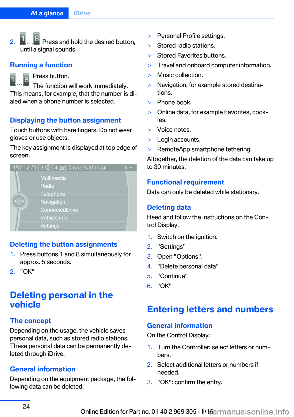
Displaying the button assignment
Touch buttons with bare fingers. Do not wear
gloves or use objects.
The key assignment is displayed at top edge of
screen.
Deleting the button assignments
1.Press buttons 1 and 8 simultaneously for
approx. 5 seconds.2."OK"
Deleting personal in the
vehicle
The concept
Depending on the usage, the vehicle saves
personal data, such as stored radio stations.
These personal data can be permanently de‐
leted through iDrive.
General information
Depending on the equipment package, the fol‐
lowing data can be deleted:
▷Personal Profile settings.▷Stored radio stations.▷Stored Favorites buttons.▷Travel and onboard computer information.▷Music collection.▷Navigation, for example stored destina‐
tions.▷Phone book.▷Online data, for example Favorites, cook‐
ies.▷Voice notes.▷Login accounts.▷RemoteApp smartphone tethering.
Altogether, the deletion of the data can take up
to 30 minutes.
Functional requirement Data can only be deleted while stationary.
Deleting data Heed and follow the instructions on the Con‐
trol Display.
1.Switch on the ignition.2."Settings"3.Open "Options".4."Delete personal data"5."Continue"6."OK"
Entering letters and numbers
General information
On the Control Display:
1.Turn the Controller: select letters or num‐
bers.2.Select additional letters or numbers if
needed.3."OK": confirm the entry.Seite 24At a glanceiDrive24
Online Edition for Part no. 01 40 2 969 305 - II/16
Page 73 of 261
Turn signal, high beams,
headlight flasher
Turn signal
Turn signal in exterior mirror
When driving and during operation of the turn
signals or hazard warning system, do not fold
in the exterior mirrors, so that the signal lights on the exterior mirror are easy to see.
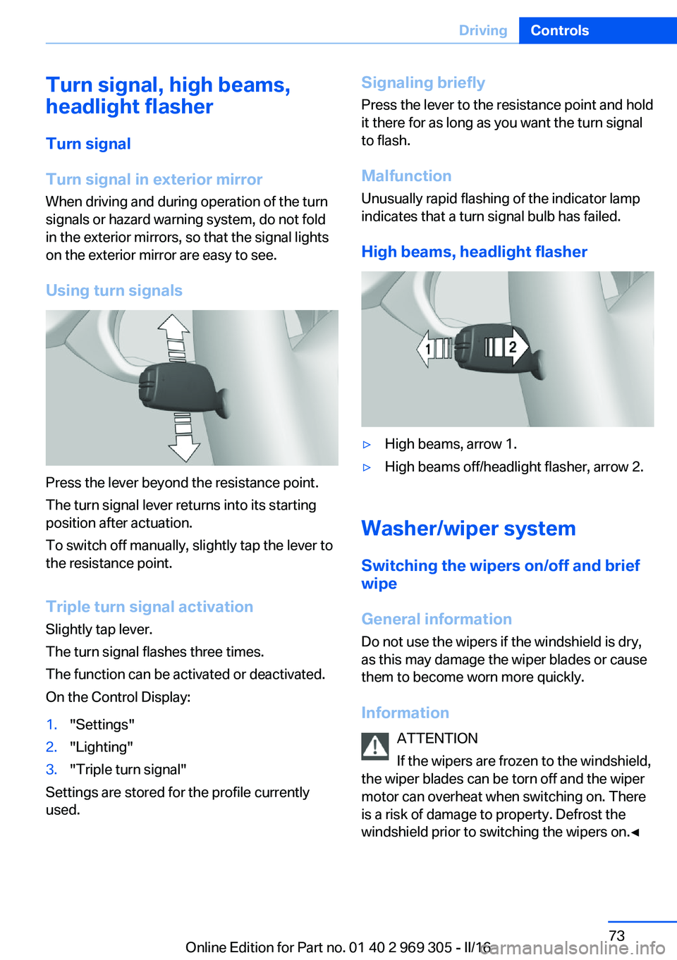
Using turn signals
Press the lever beyond the resistance point.
The turn signal lever returns into its starting
position after actuation.
To switch off manually, slightly tap the lever to
the resistance point.
Triple turn signal activation
Slightly tap lever.
The turn signal flashes three times.
The function can be activated or deactivated.
On the Control Display:
1."Settings"2."Lighting"3."Triple turn signal"
Settings are stored for the profile currently
used.
Signaling briefly
Press the lever to the resistance point and hold
it there for as long as you want the turn signal
to flash.
Malfunction Unusually rapid flashing of the indicator lamp
indicates that a turn signal bulb has failed.
High beams, headlight flasher▷High beams, arrow 1.▷High beams off/headlight flasher, arrow 2.
Washer/wiper system Switching the wipers on/off and brief
wipe
General information
Do not use the wipers if the windshield is dry,
as this may damage the wiper blades or cause them to become worn more quickly.
Information ATTENTION
If the wipers are frozen to the windshield,
the wiper blades can be torn off and the wiper
motor can overheat when switching on. There
is a risk of damage to property. Defrost the
windshield prior to switching the wipers on.◀
Seite 73DrivingControls73
Online Edition for Part no. 01 40 2 969 305 - II/16
Page 87 of 261
Dynamic Traction Control DTC, refer to
page 134.
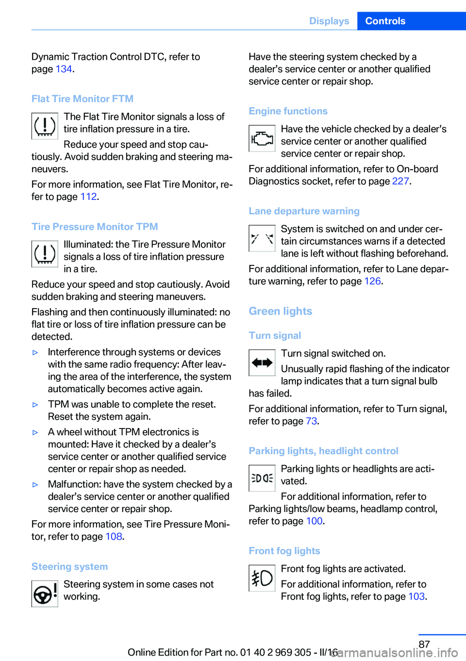
Flat Tire Monitor FTM The Flat Tire Monitor signals a loss of
tire inflation pressure in a tire.
Reduce your speed and stop cau‐
tiously. Avoid sudden braking and steering ma‐
neuvers.
For more information, see Flat Tire Monitor, re‐
fer to page 112.
Tire Pressure Monitor TPM Illuminated: the Tire Pressure Monitor
signals a loss of tire inflation pressure
in a tire.
Reduce your speed and stop cautiously. Avoid
sudden braking and steering maneuvers.
Flashing and then continuously illuminated: no
flat tire or loss of tire inflation pressure can be
detected.▷Interference through systems or devices
with the same radio frequency: After leav‐
ing the area of the interference, the system
automatically becomes active again.▷TPM was unable to complete the reset.
Reset the system again.▷A wheel without TPM electronics is
mounted: Have it checked by a dealer’s
service center or another qualified service
center or repair shop as needed.▷Malfunction: have the system checked by a
dealer’s service center or another qualified
service center or repair shop.
For more information, see Tire Pressure Moni‐
tor, refer to page 108.
Steering system Steering system in some cases not
working.
Have the steering system checked by a
dealer’s service center or another qualified
service center or repair shop.
Engine functions Have the vehicle checked by a dealer’s
service center or another qualified
service center or repair shop.
For additional information, refer to On-board
Diagnostics socket, refer to page 227.
Lane departure warning System is switched on and under cer‐
tain circumstances warns if a detected
lane is left without flashing beforehand.
For additional information, refer to Lane depar‐
ture warning, refer to page 126.
Green lights Turn signal Turn signal switched on.
Unusually rapid flashing of the indicator
lamp indicates that a turn signal bulb
has failed.
For additional information, refer to Turn signal,
refer to page 73.
Parking lights, headlight control Parking lights or headlights are acti‐
vated.
For additional information, refer to
Parking lights/low beams, headlamp control,
refer to page 100.
Front fog lights Front fog lights are activated.
For additional information, refer to
Front fog lights, refer to page 103.Seite 87DisplaysControls87
Online Edition for Part no. 01 40 2 969 305 - II/16
Page 88 of 261
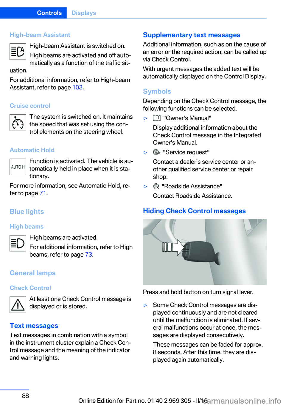
High-beam AssistantHigh-beam Assistant is switched on.
High beams are activated and off auto‐
matically as a function of the traffic sit‐
uation.
For additional information, refer to High-beam
Assistant, refer to page 103.
Cruise control The system is switched on. It maintains
the speed that was set using the con‐
trol elements on the steering wheel.
Automatic Hold Function is activated. The vehicle is au‐
tomatically held in place when it is sta‐
tionary.
For more information, see Automatic Hold, re‐
fer to page 71.
Blue lights
High beams High beams are activated.
For additional information, refer to High
beams, refer to page 73.
General lamps
Check Control At least one Check Control message is
displayed or is stored.
Text messages Text messages in combination with a symbol
in the instrument cluster explain a Check Con‐
trol message and the meaning of the indicator
and warning lights.Supplementary text messages
Additional information, such as on the cause of
an error or the required action, can be called up
via Check Control.
With urgent messages the added text will be
automatically displayed on the Control Display.
Symbols
Depending on the Check Control message, the
following functions can be selected.▷ "Owner's Manual"
Display additional information about the
Check Control message in the Integrated
Owner's Manual.▷ "Service request"
Contact a dealer’s service center or an‐
other qualified service center or repair
shop.▷ "Roadside Assistance"
Contact Roadside Assistance.
Hiding Check Control messages
Press and hold button on turn signal lever.
▷Some Check Control messages are dis‐
played continuously and are not cleared
until the malfunction is eliminated. If sev‐
eral malfunctions occur at once, the mes‐
sages are displayed consecutively.
These messages can be faded for approx.
8 seconds. After this time, they are dis‐
played again automatically.Seite 88ControlsDisplays88
Online Edition for Part no. 01 40 2 969 305 - II/16
Page 94 of 261
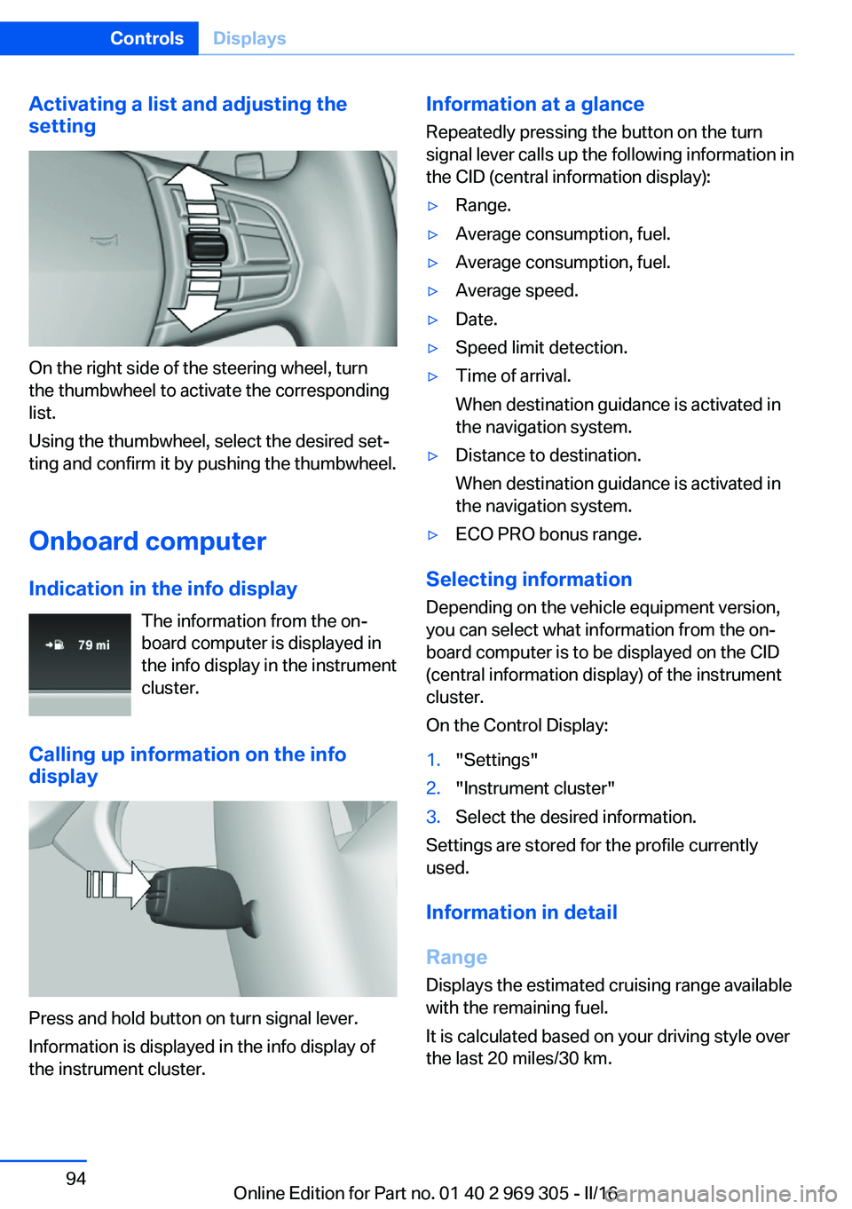
Activating a list and adjusting the
setting
On the right side of the steering wheel, turn
the thumbwheel to activate the corresponding
list.
Using the thumbwheel, select the desired set‐
ting and confirm it by pushing the thumbwheel.
Onboard computer
Indication in the info display The information from the on‐
board computer is displayed in
the info display in the instrument
cluster.
Calling up information on the info
display
Press and hold button on turn signal lever.
Information is displayed in the info display of
the instrument cluster.
Information at a glance
Repeatedly pressing the button on the turn
signal lever calls up the following information in
the CID (central information display):▷Range.▷Average consumption, fuel.▷Average consumption, fuel.▷Average speed.▷Date.▷Speed limit detection.▷Time of arrival.
When destination guidance is activated in
the navigation system.▷Distance to destination.
When destination guidance is activated in
the navigation system.▷ECO PRO bonus range.
Selecting information
Depending on the vehicle equipment version,
you can select what information from the on‐
board computer is to be displayed on the CID
(central information display) of the instrument
cluster.
On the Control Display:
1."Settings"2."Instrument cluster"3.Select the desired information.
Settings are stored for the profile currently
used.
Information in detail
Range
Displays the estimated cruising range available
with the remaining fuel.
It is calculated based on your driving style over
the last 20 miles/30 km.
Seite 94ControlsDisplays94
Online Edition for Part no. 01 40 2 969 305 - II/16
Page 95 of 261
If there is only enough fuel left for less than
45 miles/80 km, the color of the display
changes.
Average fuel consumption
The average fuel consumption is calculated for
the period while the engine is running.
The average fuel consumption is calculated for
the distance traveled since the last reset by the
onboard computer.
Average speed
Periods in which the vehicle is parked with the
engine manually stopped are not included in
the calculation of the average speed.
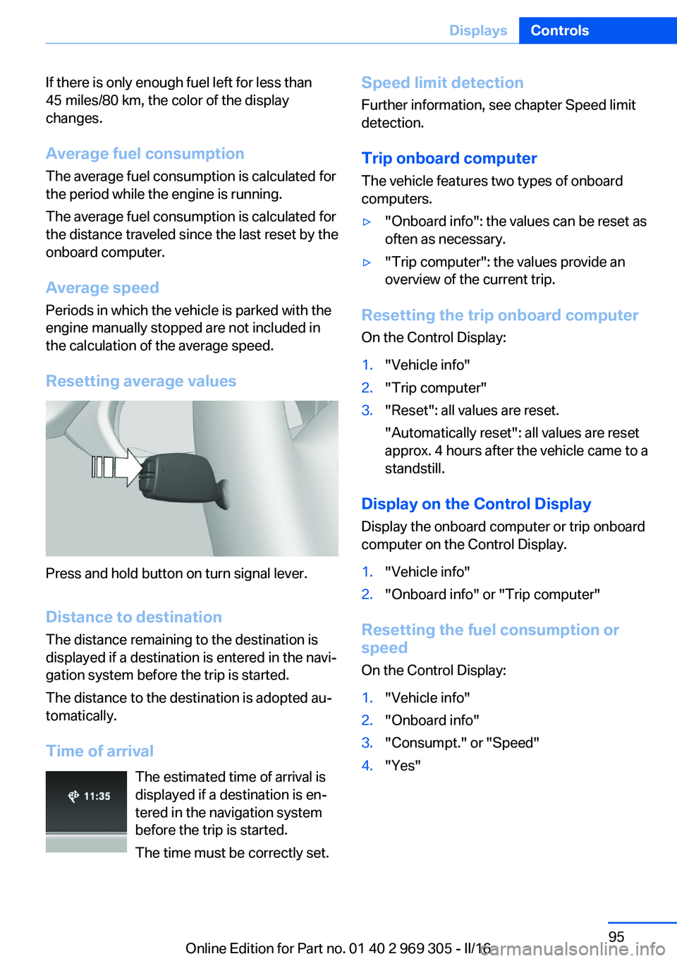
Resetting average values
Press and hold button on turn signal lever.
Distance to destination
The distance remaining to the destination is
displayed if a destination is entered in the navi‐
gation system before the trip is started.
The distance to the destination is adopted au‐
tomatically.
Time of arrival The estimated time of arrival is
displayed if a destination is en‐
tered in the navigation system
before the trip is started.
The time must be correctly set.
Speed limit detection
Further information, see chapter Speed limit
detection.
Trip onboard computer
The vehicle features two types of onboard
computers.▷"Onboard info": the values can be reset as
often as necessary.▷"Trip computer": the values provide an
overview of the current trip.
Resetting the trip onboard computer
On the Control Display:
1."Vehicle info"2."Trip computer"3."Reset": all values are reset.
"Automatically reset": all values are reset
approx. 4 hours after the vehicle came to a
standstill.
Display on the Control Display
Display the onboard computer or trip onboard
computer on the Control Display.
1."Vehicle info"2."Onboard info" or "Trip computer"
Resetting the fuel consumption or
speed
On the Control Display:
1."Vehicle info"2."Onboard info"3."Consumpt." or "Speed"4."Yes"Seite 95DisplaysControls95
Online Edition for Part no. 01 40 2 969 305 - II/16
Page 102 of 261
System limits
The automatic headlamp control cannot serve
as a substitute for your personal judgment of
lighting conditions.
E.g. the sensors are unable to detect fog or
hazy weather. To avoid safety risks under
these conditions, you should always switch on
the lights manually.
Daytime running lights
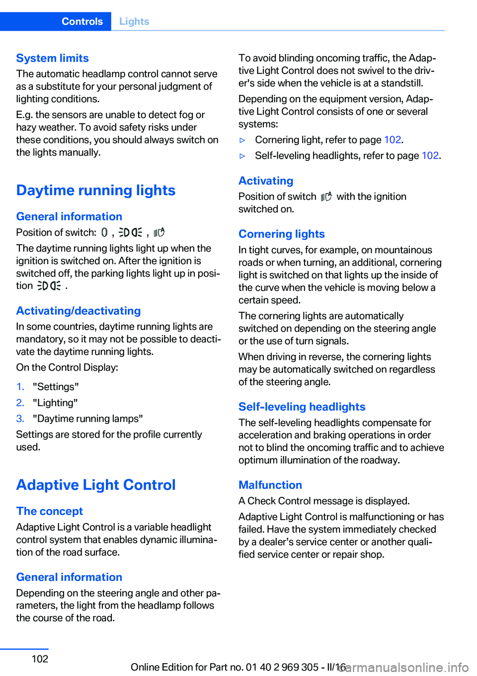
General information Position of switch:
, ,
The daytime running lights light up when the
ignition is switched on. After the ignition is
switched off, the parking lights light up in posi‐
tion
.
Activating/deactivating In some countries, daytime running lights are
mandatory, so it may not be possible to deacti‐
vate the daytime running lights.
On the Control Display:
1."Settings"2."Lighting"3."Daytime running lamps"
Settings are stored for the profile currently
used.
Adaptive Light Control
The concept Adaptive Light Control is a variable headlight
control system that enables dynamic illumina‐
tion of the road surface.
General information
Depending on the steering angle and other pa‐
rameters, the light from the headlamp follows
the course of the road.
To avoid blinding oncoming traffic, the Adap‐
tive Light Control does not swivel to the driv‐
er's side when the vehicle is at a standstill.
Depending on the equipment version, Adap‐
tive Light Control consists of one or several
systems:▷Cornering light, refer to page 102.▷Self-leveling headlights, refer to page 102.
Activating
Position of switch
with the ignition
switched on.
Cornering lights
In tight curves, for example, on mountainous
roads or when turning, an additional, cornering
light is switched on that lights up the inside of
the curve when the vehicle is moving below a certain speed.
The cornering lights are automatically
switched on depending on the steering angle
or the use of turn signals.
When driving in reverse, the cornering lights
may be automatically switched on regardless of the steering angle.
Self-leveling headlights
The self-leveling headlights compensate for
acceleration and braking operations in order
not to blind the oncoming traffic and to achieve
optimum illumination of the roadway.
Malfunction
A Check Control message is displayed.
Adaptive Light Control is malfunctioning or has
failed. Have the system immediately checked
by a dealer’s service center or another quali‐
fied service center or repair shop.
Seite 102ControlsLights102
Online Edition for Part no. 01 40 2 969 305 - II/16
Page 103 of 261
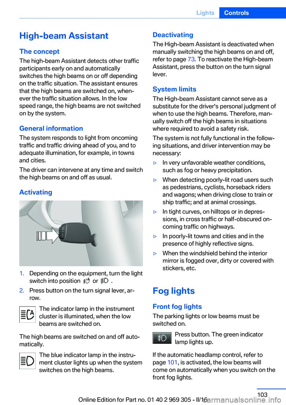
High-beam AssistantThe concept
The high-beam Assistant detects other traffic
participants early on and automatically
switches the high beams on or off depending
on the traffic situation. The assistant ensures
that the high beams are switched on, when‐
ever the traffic situation allows. In the low
speed range, the high beams are not switched
on by the system.
General information
The system responds to light from oncoming
traffic and traffic driving ahead of you, and to
adequate illumination, for example, in towns
and cities.
The driver can intervene at any time and switch
the high beams on and off as usual.
Activating1.Depending on the equipment, turn the light
switch into position
or .
2.Press button on the turn signal lever, ar‐
row.
The indicator lamp in the instrument
cluster is illuminated, when the low
beams are switched on.
The high beams are switched on and off auto‐
matically.
The blue indicator lamp in the instru‐
ment cluster lights up when the system
switches on the high beams.
Deactivating
The High-beam Assistant is deactivated when
manually switching the high beams on and off,
refer to page 73. To reactivate the High-beam
Assistant, press the button on the turn signal
lever.
System limits
The High-beam Assistant cannot serve as a
substitute for the driver's personal judgment of
when to use the high beams. Therefore, man‐
ually switch off the high beams in situations
where required to avoid a safety risk.
The system is not fully functional in the follow‐
ing situations, and driver intervention may be
necessary:▷In very unfavorable weather conditions,
such as fog or heavy precipitation.▷When detecting poorly-lit road users such
as pedestrians, cyclists, horseback riders
and wagons; when driving close to train or
ship traffic; and at animal crossings.▷In tight curves, on hilltops or in depres‐
sions, in cross traffic or half-obscured on‐
coming traffic on highways.▷In poorly-lit towns and cities and in the
presence of highly reflective signs.▷When the windshield behind the interior
mirror is fogged over, dirty or covered with
stickers, etc.
Fog lights
Front fog lights
The parking lights or low beams must be
switched on.
Press button. The green indicator
lamp lights up.
If the automatic headlamp control, refer to
page 101, is activated, the low beams will
come on automatically when you switch on the
front fog lights.
Seite 103LightsControls103
Online Edition for Part no. 01 40 2 969 305 - II/16
Page 122 of 261
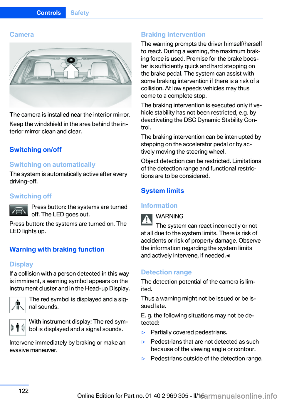
Camera
The camera is installed near the interior mirror.
Keep the windshield in the area behind the in‐
terior mirror clean and clear.
Switching on/off
Switching on automatically The system is automatically active after every
driving-off.
Switching off Press button: the systems are turned
off. The LED goes out.
Press button: the systems are turned on. The
LED lights up.
Warning with braking function
Display
If a collision with a person detected in this way
is imminent, a warning symbol appears on the
instrument cluster and in the Head-up Display.
The red symbol is displayed and a sig‐
nal sounds.
With instrument display: The red sym‐
bol is displayed and a signal sounds.
Intervene immediately by braking or make an
evasive maneuver.
Braking intervention
The warning prompts the driver himself/herself
to react. During a warning, the maximum brak‐
ing force is used. Premise for the brake boos‐
ter is sufficiently quick and hard stepping on
the brake pedal. The system can assist with
some braking intervention if there is a risk of a
collision. At low speeds vehicles may thus
come to a complete stop.
The braking intervention is executed only if ve‐
hicle stability has not been restricted, e.g. by
deactivating the DSC Dynamic Stability Con‐
trol.
The braking intervention can be interrupted by
stepping on the accelerator pedal or by ac‐
tively moving the steering wheel.
Object detection can be restricted. Limitations
of the detection range and functional restric‐
tions are to be considered.
System limits
Information WARNING
The system can react incorrectly or not
at all due to the system limits. There is risk of
accidents or risk of property damage. Observe
the information regarding the system limits
and actively intervene, if needed.◀
Detection range
The detection potential of the camera is lim‐
ited.
Thus a warning might not be issued or be is‐
sued late.
E. g. the following situations may not be de‐
tected:▷Partially covered pedestrians.▷Pedestrians that are not detected as such
because of the viewing angle or contour.▷Pedestrians outside of the detection range.Seite 122ControlsSafety122
Online Edition for Part no. 01 40 2 969 305 - II/16