ECU BMW 640I COUPE 2012 Owners Manual
[x] Cancel search | Manufacturer: BMW, Model Year: 2012, Model line: 640I COUPE, Model: BMW 640I COUPE 2012Pages: 303, PDF Size: 11.32 MB
Page 22 of 303
Voice activation systemVehicle equipment
All standard, country-specific and optional
equipment that is offered in the model series is
described in this chapter. Therefore, equipment
is also described that is not available in a vehicle,
e. g., because of the selected optional equip‐
ment or country variant. This also applies for
safety-related functions and systems.
The concept▷Most functions that are displayed on the
Control Display can be operated by spoken
commands via the voice activation system.
The system prompts you to make your en‐
tries.▷Functions that can only be used when the
vehicle is stationary cannot be operated us‐
ing the voice activation system.▷The system uses a special microphone on
the driver's side.▷›...‹ Verbal instructions in the Owner's
Manual to use with the voice activation sys‐
tem.
Requirements
Via the Control Display, set a language that is
also supported by the voice activation system
so that the spoken commands can be identified.
Set the language, refer to page 79.
Using voice activation
Activating the voice activation system
1. Press the button on the steering
wheel.2.Wait for the signal.3.Say the command.
The command is displayed in the instrument
cluster.
This symbol in the instrument cluster indi‐
cates that the voice activation system is active.
If no other commands are available, operate the
function in this case via iDrive.
Terminating the voice activation
system
Briefly press the button on the steering
wheel or ›Cancel‹.
Possible commands
Most menu items on the Control Display can be
voiced as commands.
The available commands depend on which
menu is currently displayed on the Control Dis‐
play.
There are short commands for functions of the
main menu.
Some list entries, e.g. Phone book entries, can
also be selected via the voice activation system.
Speak these list entries exactly as they are dis‐
played in the respective list.
Having possible commands read aloud
You can have the available commands read out
loud for you: ›Voice commands‹
For example, if the "Settings" menu is displayed,
the commands for the settings are read out loud.
Executing functions using short
commands
Functions on the main menu can be performed
directly by means of short commands, nearly ir‐
Seite 22At a glanceVoice activation system22
Online Edition for Part no. 01 40 2 607 971 - 09 11 490
Page 26 of 303
Opening during operation via iDrive
To move directly from the application on the
Control Display to the options menu:1. Press the button or move the controller
to the right repeatedly until the "Options"
menu is displayed.2."Display Owner's Manual"
Opening when a Check Control
message is displayed
Directly from the Check Control message on the
Control Display:
"Display Owner's Manual"
Changing between a function and the
Owner's Manual
To change from a function, e.g., radio, to the
Owner's Manual on the Control Display and to
switch between the two displays:
1. Press the button or move the controller
to the right repeatedly until the "Options"
menu is displayed.2."Display Owner's Manual"3.Select the desired page in the Owner's
Manual.4. Press the button again to return to the
function displayed last.5. Press the button to return to the page
of the Owner's Manual displayed last.
To switch back and forth repeatedly between
the function displayed last and the page of the
Owner's Manual displayed last, repeat steps 4
and 5. This opens a new panel every time.
Programmable memory buttons
General information
The Owner's Manual can be stored on the pro‐
grammable memory buttons and called up di‐
rectly.
Storing1."Owner's Manual" Select via the iDrive.2. Press the desired button for more
than 2 seconds.
Executing
Press the button.
The Owner's Manual is displayed im‐
mediately.
Seite 26At a glanceIntegrated Owner's Manual in the vehicle26
Online Edition for Part no. 01 40 2 607 971 - 09 11 490
Page 30 of 303
Opening and closingVehicle equipment
All standard, country-specific and optional
equipment that is offered in the model series is
described in this chapter. Therefore, equipment
is also described that is not available in a vehicle,
e. g., because of the selected optional equip‐
ment or country variant. This also applies for
safety-related functions and systems.
Remote control/key
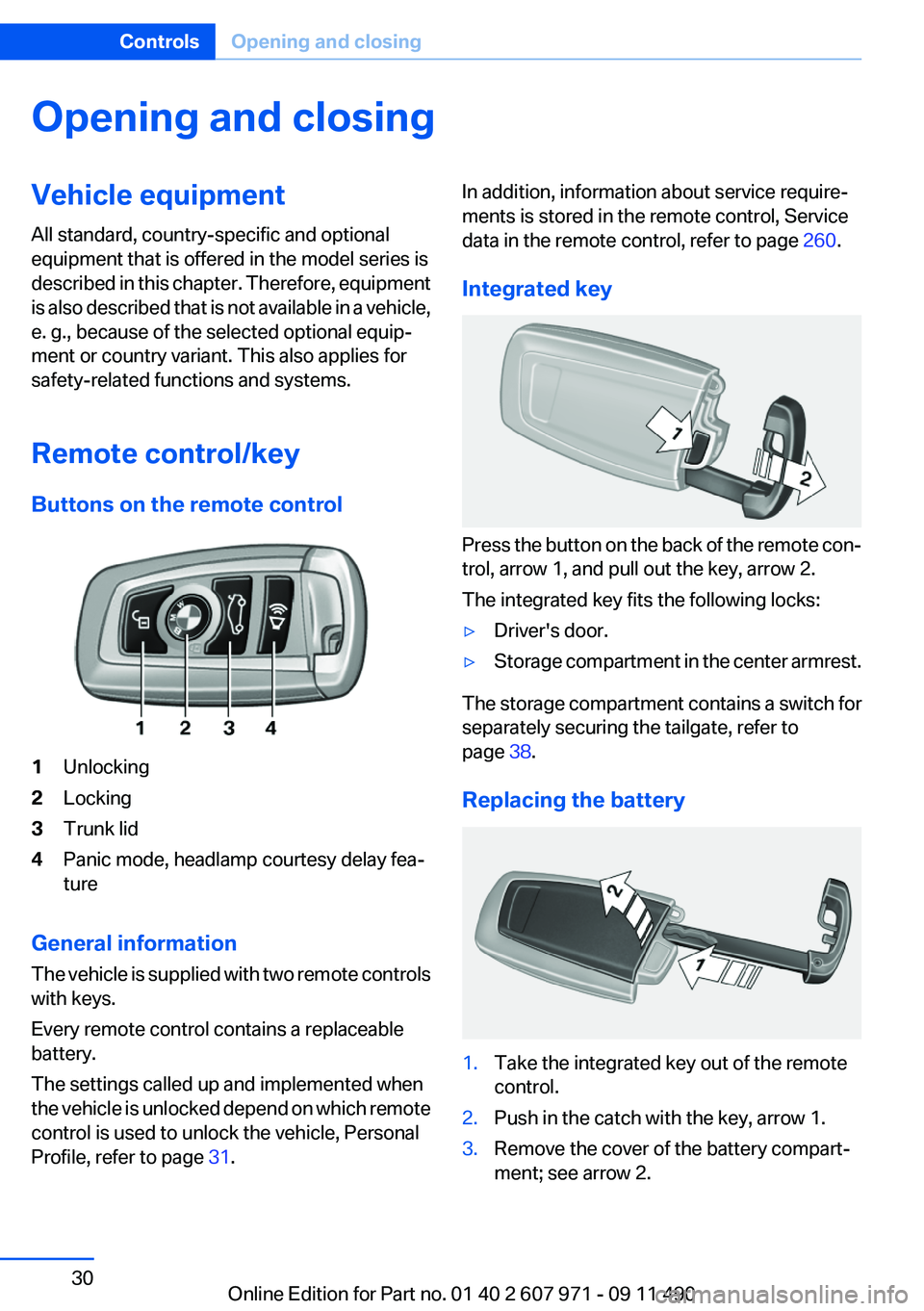
Buttons on the remote control1Unlocking2Locking3Trunk lid4Panic mode, headlamp courtesy delay fea‐
ture
General information
The vehicle is supplied with two remote controls
with keys.
Every remote control contains a replaceable
battery.
The settings called up and implemented when
the vehicle is unlocked depend on which remote
control is used to unlock the vehicle, Personal
Profile, refer to page 31.
In addition, information about service require‐
ments is stored in the remote control, Service
data in the remote control, refer to page 260.
Integrated key
Press the button on the back of the remote con‐
trol, arrow 1, and pull out the key, arrow 2.
The integrated key fits the following locks:
▷Driver's door.▷Storage compartment in the center armrest.
The storage compartment contains a switch for
separately securing the tailgate, refer to
page 38.
Replacing the battery
1.Take the integrated key out of the remote
control.2.Push in the catch with the key, arrow 1.3.Remove the cover of the battery compart‐
ment; see arrow 2.Seite 30ControlsOpening and closing30
Online Edition for Part no. 01 40 2 607 971 - 09 11 490
Page 37 of 303
Locking the doors and trunk lid at once
To lock all doors and the trunk lid at once:1.With the doors closed, lock the vehicle using
the button for the central locking system in
the interior.2.Unlock and open the driver's or front pas‐
senger door.3.Lock the vehicle.▷Lock the driver's door using the
integrated key in the door lock, or▷Press down the lock button of the front
passenger door and close the door from
the outside.
The fuel filler flap can only be locked using the
remote control.
Manual operation
If an electrical malfunction occurs, lock or unlock
the vehicle using the integrated key via the door
lock on the driver's door.
Opening and closing: from the
inside
Locking and unlocking
Pressing the buttons locks and unlocks the
doors and the trunk lid when the doors are
closed, but they are not secured against theft.
The fuel filler flap remains unlocked.
Unlocking and opening▷Either unlock the doors together using the
button for the central locking system and
then pull the door handle above the armrest
or▷Pull the door opener twice individually on
each door: the first time unlocks the door,
the second time opens it.
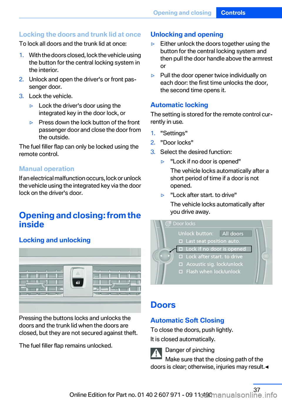
Automatic locking
The setting is stored for the remote control cur‐
rently in use.
1."Settings"2."Door locks"3.Select the desired function:▷"Lock if no door is opened"
The vehicle locks automatically after a
short period of time if a door is not
opened.▷"Lock after start. to drive"
The vehicle locks automatically after
you drive away.
Doors
Automatic Soft Closing
To close the doors, push lightly.
It is closed automatically.
Danger of pinching
Make sure that the closing path of the
doors is clear; otherwise, injuries may result.◀
Seite 37Opening and closingControls37
Online Edition for Part no. 01 40 2 607 971 - 09 11 490
Page 38 of 303
Trunk lid
Opening
During opening, the trunk lid pivots back and up.
Ensure that adequate clearance is available be‐
fore opening.
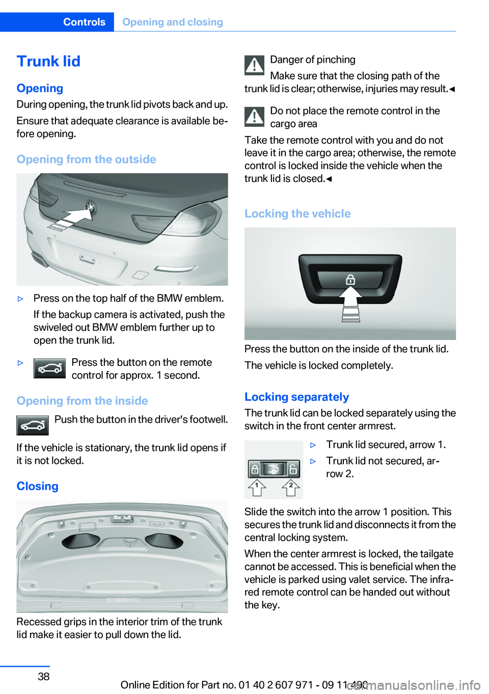
Opening from the outside▷Press on the top half of the BMW emblem.
If the backup camera is activated, push the
swiveled out BMW emblem further up to
open the trunk lid.▷Press the button on the remote
control for approx. 1 second.
Opening from the inside
Push the button in the driver's footwell.
If the vehicle is stationary, the trunk lid opens if
it is not locked.
Closing
Recessed grips in the interior trim of the trunk
lid make it easier to pull down the lid.
Danger of pinching
Make sure that the closing path of the
trunk lid is clear; otherwise, injuries may result. ◀
Do not place the remote control in the
cargo area
Take the remote control with you and do not
leave it in the cargo area; otherwise, the remote
control is locked inside the vehicle when the
trunk lid is closed.◀
Locking the vehicle
Press the button on the inside of the trunk lid.
The vehicle is locked completely.
Locking separately
The trunk lid can be locked separately using the
switch in the front center armrest.
▷Trunk lid secured, arrow 1.▷Trunk lid not secured, ar‐
row 2.
Slide the switch into the arrow 1 position. This
secures the trunk lid and disconnects it from the
central locking system.
When the center armrest is locked, the tailgate
cannot be accessed. This is beneficial when the
vehicle is parked using valet service. The infra‐
red remote control can be handed out without
the key.
Seite 38ControlsOpening and closing38
Online Edition for Part no. 01 40 2 607 971 - 09 11 490
Page 55 of 303
Seat position and height
Before installing a child restraint fixing system,
move the front passenger seat as far back as
possible and adjust its height to the highest po‐
sition to obtain the best possible position for the
belt and to offer optimal protection in the event
of an accident.
Do not change the seat position and height after
this.
Backrest width
Before installing a child restraint fixing system in
the front passenger seat, open the backrest
width completely. Do not change the backrest
width again and do not call up a memory posi‐
tion.
Backrest width for the child seat
Before installing a child restraint fixing
system in the front passenger seat, the backrest
width must be opened completely. Do not
change the adjustment after this; otherwise, the
stability of the child seat will be reduced.◀
Child seat security
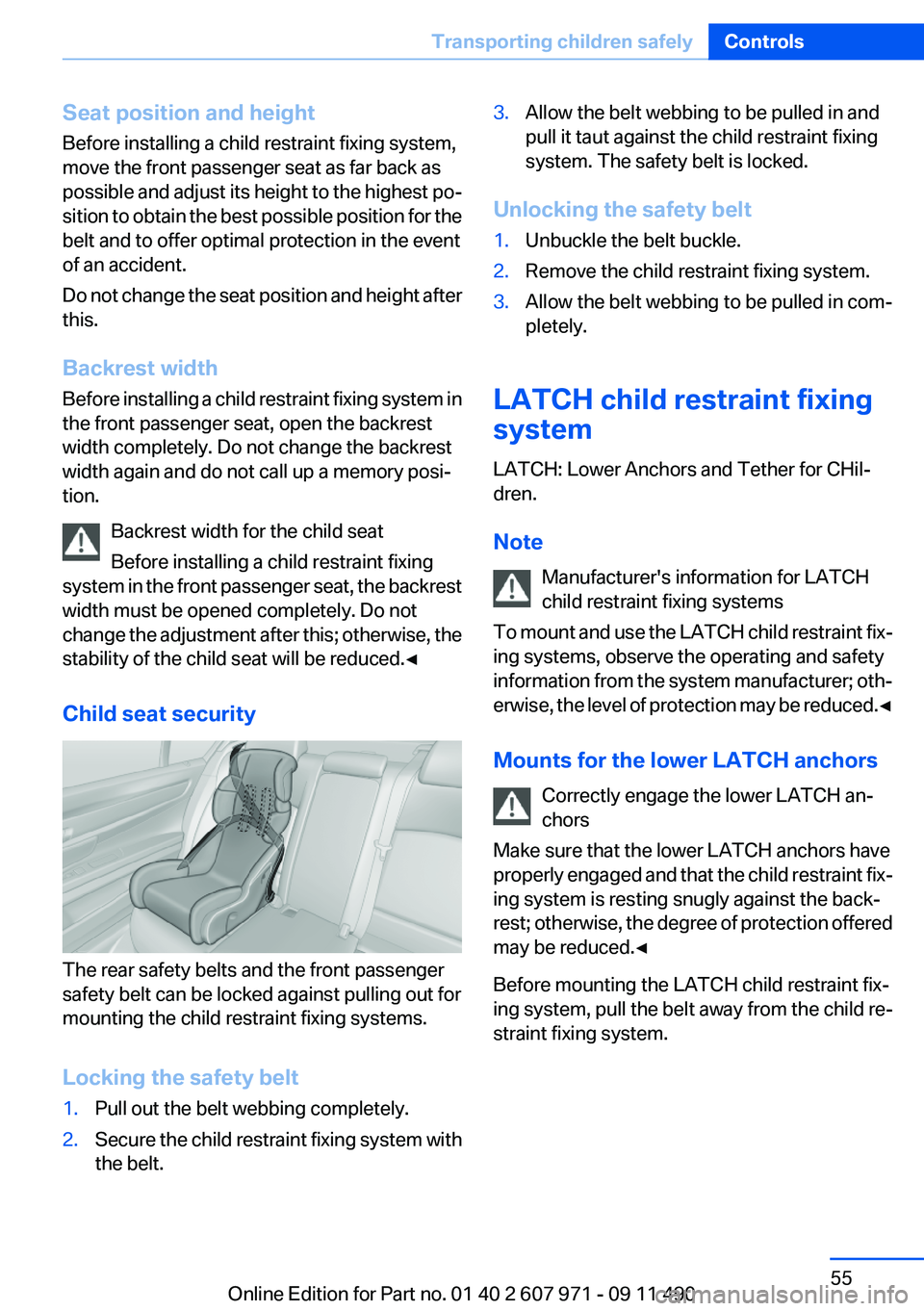
The rear safety belts and the front passenger
safety belt can be locked against pulling out for
mounting the child restraint fixing systems.
Locking the safety belt
1.Pull out the belt webbing completely.2.Secure the child restraint fixing system with
the belt.3.Allow the belt webbing to be pulled in and
pull it taut against the child restraint fixing
system. The safety belt is locked.
Unlocking the safety belt
1.Unbuckle the belt buckle.2.Remove the child restraint fixing system.3.Allow the belt webbing to be pulled in com‐
pletely.
LATCH child restraint fixing
system
LATCH: Lower Anchors and Tether for CHil‐
dren.
Note Manufacturer's information for LATCH
child restraint fixing systems
To mount and use the LATCH child restraint fix‐
ing systems, observe the operating and safety
information from the system manufacturer; oth‐
erwise, the level of protection may be reduced. ◀
Mounts for the lower LATCH anchors Correctly engage the lower LATCH an‐
chors
Make sure that the lower LATCH anchors have
properly engaged and that the child restraint fix‐
ing system is resting snugly against the back‐
rest; otherwise, the degree of protection offered
may be reduced.◀
Before mounting the LATCH child restraint fix‐
ing system, pull the belt away from the child re‐
straint fixing system.
Seite 55Transporting children safelyControls55
Online Edition for Part no. 01 40 2 607 971 - 09 11 490
Page 56 of 303
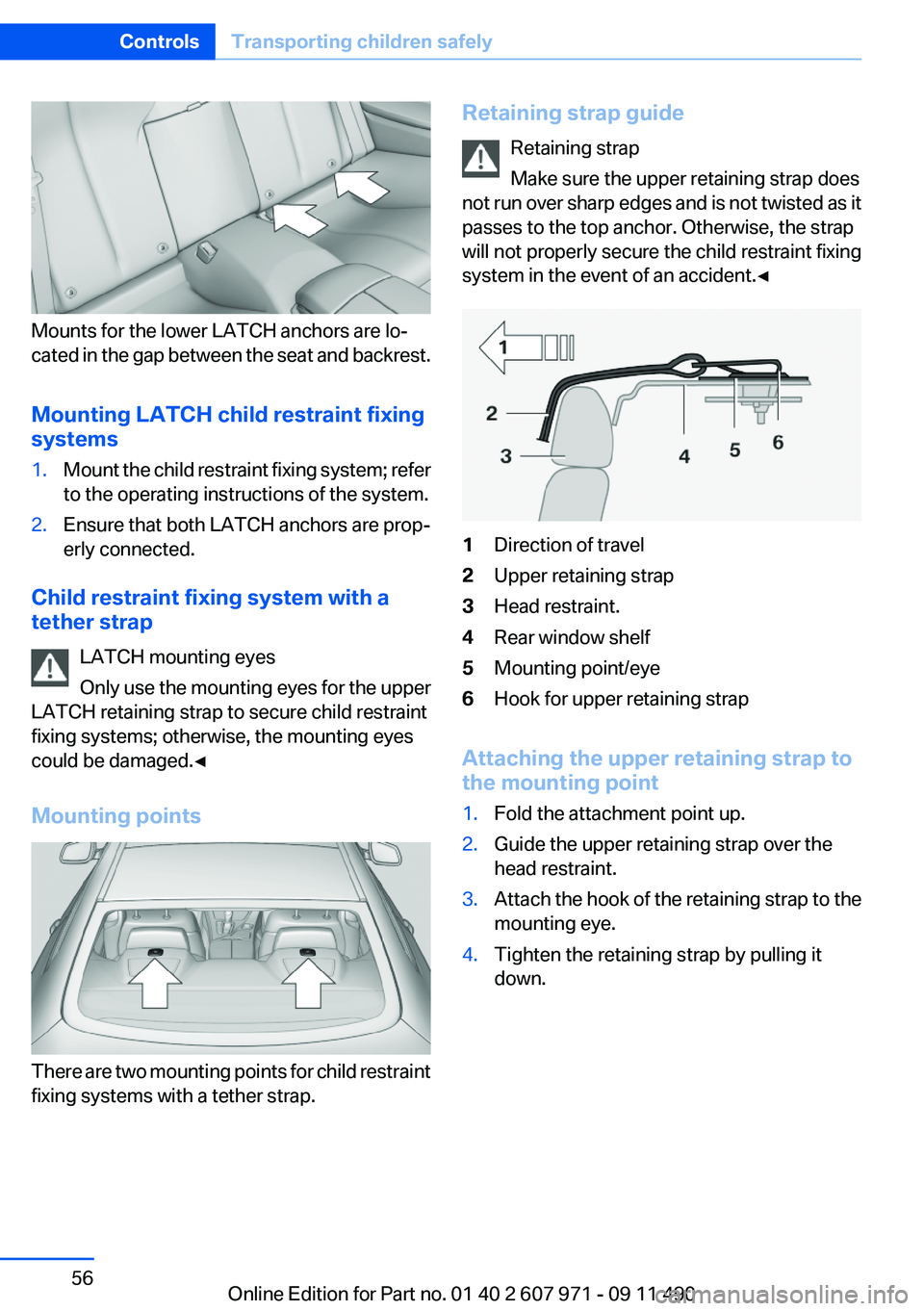
Mounts for the lower LATCH anchors are lo‐
cated in the gap between the seat and backrest.
Mounting LATCH child restraint fixing
systems
1.Mount the child restraint fixing system; refer
to the operating instructions of the system.2.Ensure that both LATCH anchors are prop‐
erly connected.
Child restraint fixing system with a
tether strap
LATCH mounting eyes
Only use the mounting eyes for the upper
LATCH retaining strap to secure child restraint
fixing systems; otherwise, the mounting eyes
could be damaged.◀
Mounting points
There are two mounting points for child restraint
fixing systems with a tether strap.
Retaining strap guide
Retaining strap
Make sure the upper retaining strap does
not run over sharp edges and is not twisted as it
passes to the top anchor. Otherwise, the strap
will not properly secure the child restraint fixing
system in the event of an accident.◀1Direction of travel2Upper retaining strap3Head restraint.4Rear window shelf5Mounting point/eye6Hook for upper retaining strap
Attaching the upper retaining strap to
the mounting point
1.Fold the attachment point up.2.Guide the upper retaining strap over the
head restraint.3.Attach the hook of the retaining strap to the
mounting eye.4.Tighten the retaining strap by pulling it
down.Seite 56ControlsTransporting children safely56
Online Edition for Part no. 01 40 2 607 971 - 09 11 490
Page 59 of 303
Set the parking brake and further secure
the vehicle as required
Set the parking brake firmly when parking; oth‐
erwise, the vehicle could roll. On steep upward
and downward inclines, further secure the vehi‐
cle, for example, by turning the steering wheel in
the direction of the curb. ◀
Before driving into a car wash
In order for the vehicle to be able to roll into a car
wash, heed the information regarding Washing
in automatic car washes, refer to page 273.
Manual transmission
Switching off the engine1.With the vehicle at a standstill, press the
Start/Stop button.2.Shift into first gear or reverse.3.Set the parking brake.
Automatic-Transmission
Switching off the engine
1.Engage transmission position P with the ve‐
hicle stopped.2.Press the Start/Stop button.
The engine is switched off.
The radio ready state is switched on.3.Set the parking brake.
Automatic Engine Start/Stop
Function
The concept
The automatic engine start-stop function helps
save fuel. The system switches off the engine
during a stop, e. g., in a traffic congestion or at
traffic lights. The ignition remains switched on.
The engine starts again automatically for driving
off.
Automatic mode
The automatic engine start/stop function is op‐
erational after each engine start.
The function is activated above a certain speed.▷Automatic transmission: from 5 mph, ap‐
prox. 9 km/h.
Engine stop
The engine is switched off automatically during
a stop under the following conditions:
Automatic transmission:
▷The selector lever is in transmission position
D.▷The brake pedal remains pressed while the
vehicle is stationary or the vehicle is held by
Automatic Hold.▷The driver's safety belt is buckled or the
driver's door is closed.
The air volume of the air conditioner is reduced
when the engine is switched off.
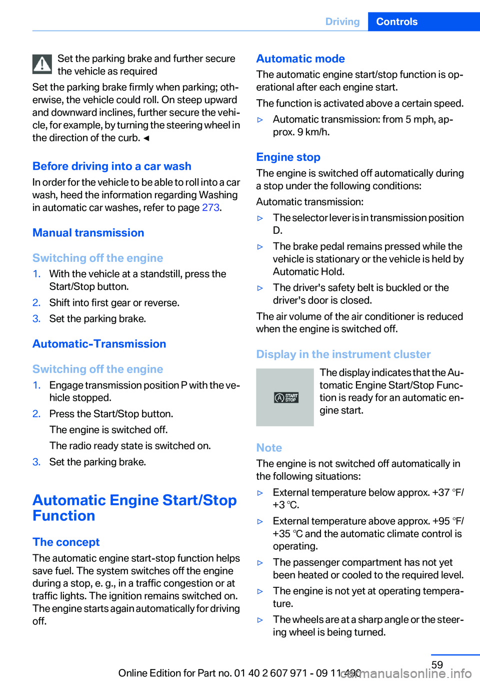
Display in the instrument cluster The display indicates that the Au‐
tomatic Engine Start/Stop Func‐
tion is ready for an automatic en‐
gine start.
Note
The engine is not switched off automatically in
the following situations:
▷External temperature below approx. +37 ℉/
+3 ℃.▷External temperature above approx. +95 ℉/
+35 ℃ and the automatic climate control is
operating.▷The passenger compartment has not yet
been heated or cooled to the required level.▷The engine is not yet at operating tempera‐
ture.▷The wheels are at a sharp angle or the steer‐
ing wheel is being turned.Seite 59DrivingControls59
Online Edition for Part no. 01 40 2 607 971 - 09 11 490
Page 61 of 303
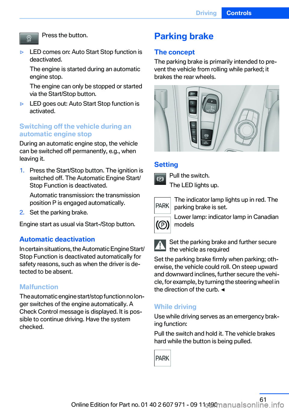
Press the button.▷LED comes on: Auto Start Stop function is
deactivated.
The engine is started during an automatic
engine stop.
The engine can only be stopped or started
via the Start/Stop button.▷LED goes out: Auto Start Stop function is
activated.
Switching off the vehicle during an
automatic engine stop
During an automatic engine stop, the vehicle
can be switched off permanently, e.g., when
leaving it.
1.Press the Start/Stop button. The ignition is
switched off. The Automatic Engine Start/
Stop Function is deactivated.
Automatic transmission: the transmission
position P is engaged automatically.2.Set the parking brake.
Engine start as usual via Start-/Stop button.
Automatic deactivation
In certain situations, the Automatic Engine Start/
Stop Function is deactivated automatically for
safety reasons, such as when the driver is de‐
tected to be absent.
Malfunction
The automatic engine start/stop function no lon‐
ger switches of the engine automatically. A
Check Control message is displayed. It is pos‐
sible to continue driving. Have the system
checked.
Parking brake
The concept
The parking brake is primarily intended to pre‐
vent the vehicle from rolling while parked; it
brakes the rear wheels.
Setting
Pull the switch.
The LED lights up.
The indicator lamp lights up in red. The
parking brake is set.
Lower lamp: indicator lamp in Canadian
models
Set the parking brake and further secure
the vehicle as required
Set the parking brake firmly when parking; oth‐
erwise, the vehicle could roll. On steep upward
and downward inclines, further secure the vehi‐
cle, for example, by turning the steering wheel in
the direction of the curb. ◀
While driving
Use while driving serves as an emergency brak‐
ing function:
Pull the switch and hold it. The vehicle brakes
hard while the button is being pulled.
Seite 61DrivingControls61
Online Edition for Part no. 01 40 2 607 971 - 09 11 490
Page 63 of 303
The LED and the letters AUTO H light up.The indicator lamp lights up.
Automatic Hold is activated.
Deactivating Press the button again.
The LED and the letters AUTO H go
out.
Automatic Hold is deactivated.
If the vehicle is being held by Automatic Hold,
press on the brake pedal to deactivate it.
When the parking brake, refer to page 61, is set
manually, Automatic Hold is deactivated auto‐
matically.
Driving
Automatic Hold is activated: the vehicle is auto‐
matically secured against rolling when it stops.
The indicator lamp lights up in green.
Step on the accelerator pedal to drive
off.
The brake is released automatically.
The indicator lamp goes out.
Lower lamp: indicator lamp in Canadian models
Before driving into a car wash
Deactivate Automatic Hold; otherwise, the
parking brake will be set when the vehicle is sta‐
tionary and the vehicle will no longer be able to
roll.◀
Parking
The parking brake is automatically set if the en‐
gine is switched off while the vehicle is being
held by Automatic Hold.
The indicator lamp changes from green
to red.
The parking brake is not set if the engine
is switched off while the vehicle is coast‐ing to a halt. Automatic Hold is deactivated.
Lower lamp: indicator lamp in Canadian models
Automatic Hold remains activated during an en‐
gine stop brought about by the Automatic En‐
gine Start/Stop Function.
Take the remote control with you
Take the remote control with you when
leaving the vehicle so that children, for example,
cannot release the parking brake.◀
Malfunction
In the event of a failure or malfunction of the
parking brake, secure the vehicle against rolling
using a wheel chock, for example, when leaving
it.
Turn signal, high beams,
headlamp flasher
Turn signal
Using turn signals
Press the lever beyond the resistance point.
To switch off manually, press the lever to the re‐
sistance point.
Unusually rapid flashing of the indicator lamp in‐
dicates that a turn signal bulb has failed.
Triple turn signal activation
Press the lever to the resistance point.
The turn signal flashes three times.
Seite 63DrivingControls63
Online Edition for Part no. 01 40 2 607 971 - 09 11 490