parts BMW 640I GRAN COUPE 2014 Owners Manual
[x] Cancel search | Manufacturer: BMW, Model Year: 2014, Model line: 640I GRAN COUPE, Model: BMW 640I GRAN COUPE 2014Pages: 243, PDF Size: 8.02 MB
Page 7 of 243
scribed in this Owner's Manual may differ from
those in your vehicle.
Updates made after the editorial
deadline
Any updates made after the editorial deadline
for the Owner's Manuals are located in the ap‐
pendix of the printed quick reference for the
vehicle.
For your own safety Maintenance and repairs
Advanced technology, e.g., the use of modern
materials and high-performance electronics,
requires suitable maintenance and repair
methods.
Therefore, have this work performed only by a
BMW center or a workshop that works accord‐
ing to BMW repair procedures with appropri‐
ately trained personnel.
If this work is not carried out properly, there is
the danger of subsequent damage and related
safety hazards.
Parts and Accessories
For your own safety, use genuine parts and ac‐
cessories approved by BMW. When you pur‐
chase accessories tested and approved by
BMW and Genuine BMW Parts, you simultane‐
ously acquire the assurance that they have
been thoroughly tested by BMW to ensure op‐
timum performance when installed on your ve‐
hicle. BMW warrants these parts to be free
from defects in material and workmanship.
BMW will not accept any liability for damage
resulting from installation of parts and acces‐
sories not approved by BMW. BMW cannot
test every product made by other manufactur‐
ers to verify if it can be used on a BMW safely
and without risk to either the vehicle, its opera‐
tion, or its occupants. Genuine BMW Parts,
BMW Accessories and other products ap‐
proved by BMW, together with professionaladvice on using these items, are available from
all BMW centers. Installation and operation of
non-BMW approved accessories such as
alarms, radios, amplifiers, radar detectors,
wheels, suspension components, brake dust
shields, telephones, including operation of any
mobile phone from within the vehicle without
using an externally mounted antenna, or trans‐
ceiver equipment, for instance, CBs, walkie-
talkies, ham radios or similar accessories, may
cause extensive damage to the vehicle, com‐
promise its safety, interfere with the vehicle's
electrical system or affect the validity of the
BMW Limited Warranty. See your BMW center
for additional information. Maintenance, re‐
placement, or repair of the emission control
devices and systems may be performed by any
automotive repair establishment or individual
using any certified automotive part.
California Proposition 65 WarningCalifornia laws require us to state the following
warning:
Engine exhaust and a wide variety of automo‐
bile components and parts, including compo‐
nents found in the interior furnishings in a vehi‐
cle, contain or emit chemicals known to the
State of California to cause cancer and birth
defects and reproductive harm. In addition,
certain fluids contained in vehicles and certain
products of component wear contain or emit
chemicals known to the State of California to
cause cancer and birth defects or other repro‐
ductive harm. Battery posts, terminals and re‐
lated accessories contain lead and lead com‐
pounds. Wash your hands after handling. Used
engine oil contains chemicals that have caused
cancer in laboratory animals. Always protect
your skin by washing thoroughly with soap and
water.
Service and warranty We recommend that you read this publication
thoroughly. Your vehicle is covered by the fol‐
lowing warranties:Seite 7Notes7
Online Edition for Part no. 01 40 2 909 877 - VI/13
Page 25 of 243
Integrated Owner's Manual in the vehicleVehicle equipmentAll standard, country-specific and optional
equipment that is offered in the model series is
described in this chapter. Therefore, equip‐
ment is also described that is not available in a
vehicle, e. g., because of the selected optional
equipment or country variant. This also applies
for safety-related functions and systems.
Integrated Owner's Manual
in the vehicle
The Integrated Owner's Manual can be dis‐
played on the Control Display. The equipment
and functions that are in the vehicle are descri‐
bed therein.
Components of the integrated
Owner's Manual
The integrated Owner's Manual consists of
three parts, which offer various levels of infor‐
mation or access possibilities.
Quick Reference Guide Located in the Quick Reference is important
information for the operation of the vehicle, the
operation of basic vehicle functions or for what
to do in the event of a flat tire. This information
can also be displayed during driving.
Search by pictures
Information and descriptions based on illustra‐
tions can be searched via search by pictures.
This is helpful, for example, if the description of
an outfitting package that cannot be named is
needed.
Owner's Manual
Information and descriptions can be searched
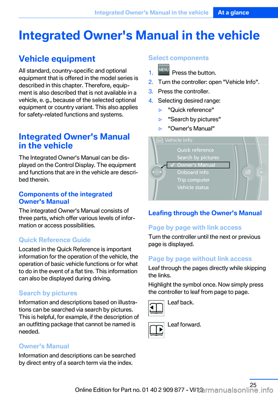
by direct entry of a search term via the index.Select components1. Press the button.2.Turn the controller: open "Vehicle Info".3.Press the controller.4.Selecting desired range:▷"Quick reference"▷"Search by pictures"▷"Owner's Manual"
Leafing through the Owner's Manual
Page by page with link access
Turn the controller until the next or previous
page is displayed.
Page by page without link access
Leaf through the pages directly while skipping
the links.
Highlight the symbol once. Now simply press
the controller to leaf from page to page.
Leaf back.
Leaf forward.
Seite 25Integrated Owner's Manual in the vehicleAt a glance25
Online Edition for Part no. 01 40 2 909 877 - VI/13
Page 67 of 243
Clean the windshield, headlamps
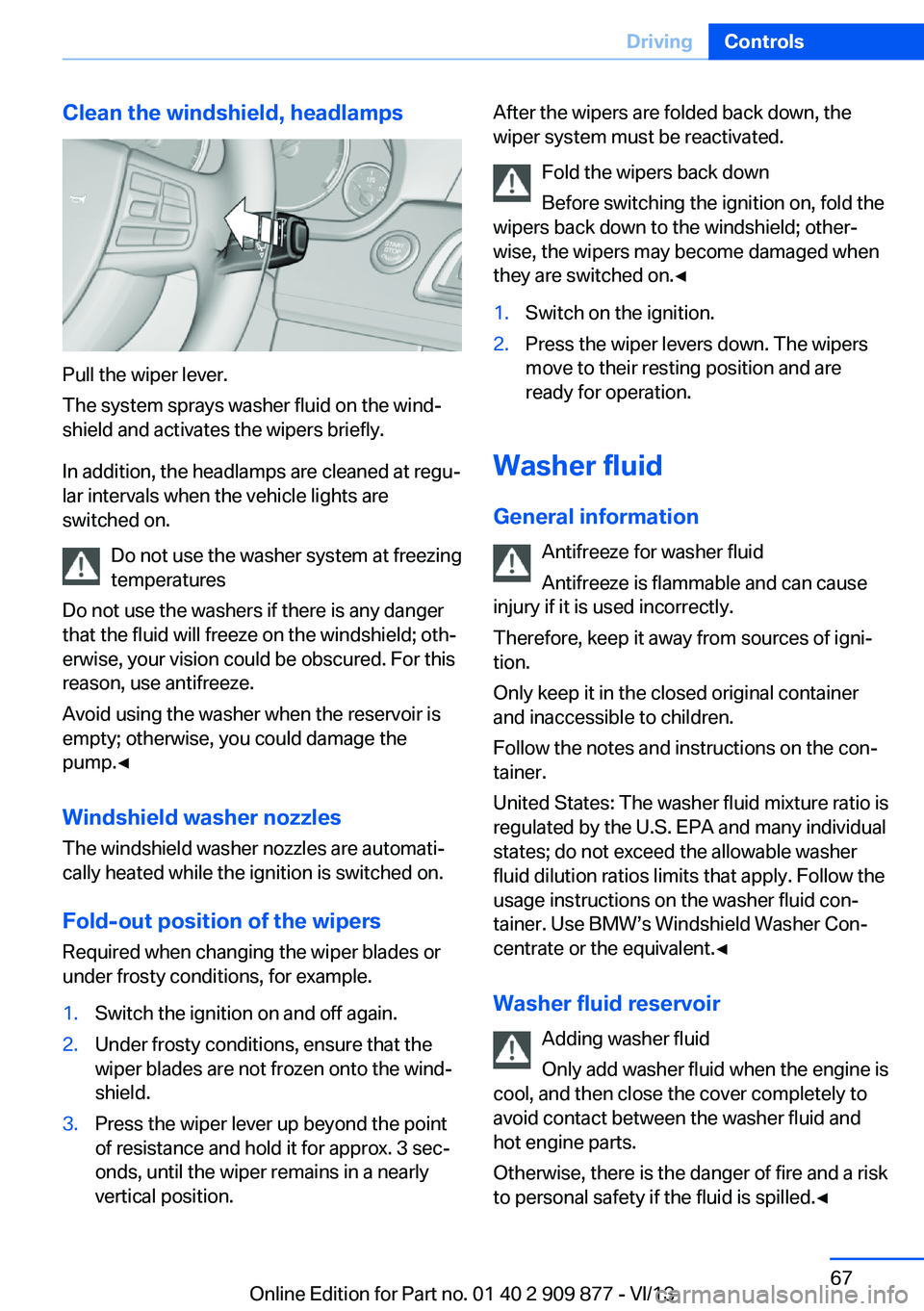
Pull the wiper lever.
The system sprays washer fluid on the wind‐
shield and activates the wipers briefly.
In addition, the headlamps are cleaned at regu‐
lar intervals when the vehicle lights are
switched on.
Do not use the washer system at freezing
temperatures
Do not use the washers if there is any danger
that the fluid will freeze on the windshield; oth‐
erwise, your vision could be obscured. For this
reason, use antifreeze.
Avoid using the washer when the reservoir is
empty; otherwise, you could damage the
pump.◀
Windshield washer nozzles
The windshield washer nozzles are automati‐
cally heated while the ignition is switched on.
Fold-out position of the wipers Required when changing the wiper blades or
under frosty conditions, for example.
1.Switch the ignition on and off again.2.Under frosty conditions, ensure that the
wiper blades are not frozen onto the wind‐
shield.3.Press the wiper lever up beyond the point
of resistance and hold it for approx. 3 sec‐
onds, until the wiper remains in a nearly
vertical position.After the wipers are folded back down, the
wiper system must be reactivated.
Fold the wipers back down
Before switching the ignition on, fold the
wipers back down to the windshield; other‐
wise, the wipers may become damaged when
they are switched on.◀1.Switch on the ignition.2.Press the wiper levers down. The wipers
move to their resting position and are
ready for operation.
Washer fluid
General information Antifreeze for washer fluid
Antifreeze is flammable and can cause
injury if it is used incorrectly.
Therefore, keep it away from sources of igni‐
tion.
Only keep it in the closed original container
and inaccessible to children.
Follow the notes and instructions on the con‐
tainer.
United States: The washer fluid mixture ratio is
regulated by the U.S. EPA and many individual
states; do not exceed the allowable washer
fluid dilution ratios limits that apply. Follow the
usage instructions on the washer fluid con‐
tainer. Use BMW’s Windshield Washer Con‐
centrate or the equivalent.◀
Washer fluid reservoir Adding washer fluid
Only add washer fluid when the engine is
cool, and then close the cover completely to
avoid contact between the washer fluid and
hot engine parts.
Otherwise, there is the danger of fire and a risk
to personal safety if the fluid is spilled.◀
Seite 67DrivingControls67
Online Edition for Part no. 01 40 2 909 877 - VI/13
Page 110 of 243
Press the button.
The LED goes out. Switching on heat image additionally
The heat image from the Night Vision camera
can also be displayed on the Control Display.
This function has no effect on object detec‐
tion.
Press the button.
The image from the camera is displayed on the
Control Display.
Adjustments via the iDrive
With heat image switched on:1.Press the controller.2.Select brightness or contrast.▷ Select the symbol.▷ Select the symbol.3.Turn the controller until the desired setting
is reached, and press the controller.
Display
Warning of people or animals in
danger
If a collision with a person or an animal de‐
tected in this way is imminent, a warning sym‐
bol appears on the instrument cluster and in
the Head-up Display.
Although both the shape and the heat radiation
are analyzed, false warnings cannot be ruled
out.
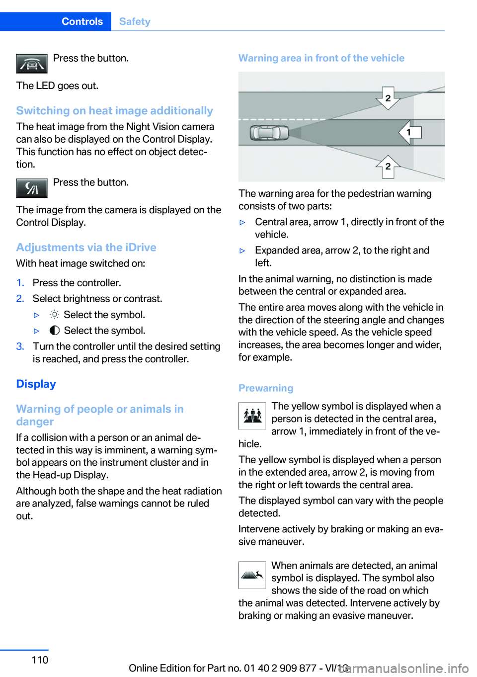
Warning area in front of the vehicle
The warning area for the pedestrian warning
consists of two parts:
▷Central area, arrow 1, directly in front of the
vehicle.▷Expanded area, arrow 2, to the right and
left.
In the animal warning, no distinction is made
between the central or expanded area.
The entire area moves along with the vehicle in
the direction of the steering angle and changes
with the vehicle speed. As the vehicle speed
increases, the area becomes longer and wider,
for example.
Prewarning The yellow symbol is displayed when aperson is detected in the central area,
arrow 1, immediately in front of the ve‐
hicle.
The yellow symbol is displayed when a person
in the extended area, arrow 2, is moving from
the right or left towards the central area.
The displayed symbol can vary with the people
detected.
Intervene actively by braking or making an eva‐
sive maneuver.
When animals are detected, an animal
symbol is displayed. The symbol also
shows the side of the road on which
the animal was detected. Intervene actively by
braking or making an evasive maneuver.
Seite 110ControlsSafety110
Online Edition for Part no. 01 40 2 909 877 - VI/13
Page 164 of 243
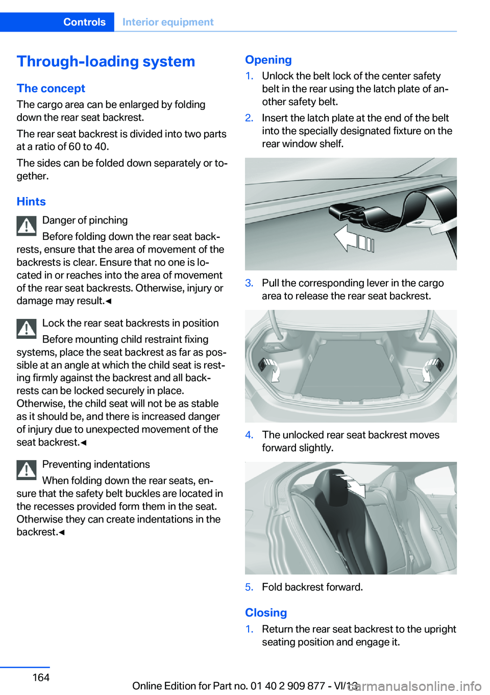
Through-loading systemThe concept The cargo area can be enlarged by folding
down the rear seat backrest.
The rear seat backrest is divided into two parts at a ratio of 60 to 40.
The sides can be folded down separately or to‐
gether.
Hints Danger of pinching
Before folding down the rear seat back‐
rests, ensure that the area of movement of the
backrests is clear. Ensure that no one is lo‐
cated in or reaches into the area of movement
of the rear seat backrests. Otherwise, injury or
damage may result.◀
Lock the rear seat backrests in positionBefore mounting child restraint fixing
systems, place the seat backrest as far as pos‐
sible at an angle at which the child seat is rest‐
ing firmly against the backrest and all back‐
rests can be locked securely in place.
Otherwise, the child seat will not be as stable
as it should be, and there is increased danger
of injury due to unexpected movement of the
seat backrest.◀
Preventing indentations
When folding down the rear seats, en‐
sure that the safety belt buckles are located in
the recesses provided form them in the seat.
Otherwise they can create indentations in the
backrest.◀Opening1.Unlock the belt lock of the center safety
belt in the rear using the latch plate of an‐
other safety belt.2.Insert the latch plate at the end of the belt
into the specially designated fixture on the
rear window shelf.3.Pull the corresponding lever in the cargo
area to release the rear seat backrest.4.The unlocked rear seat backrest moves
forward slightly.5.Fold backrest forward.
Closing
1.Return the rear seat backrest to the upright
seating position and engage it.Seite 164ControlsInterior equipment164
Online Edition for Part no. 01 40 2 909 877 - VI/13
Page 174 of 243
Things to remember when drivingVehicle equipment
All standard, country-specific and optional
equipment that is offered in the model series is
described in this chapter. Therefore, equip‐
ment is also described that is not available in a
vehicle, e. g., because of the selected optional
equipment or country variant. This also applies
for safety-related functions and systems.
Breaking-in period General information Moving parts need to be broken in to adjust to
each other.
The following instructions will help achieve a
long vehicle life and good economy.
Engine and differential Always obey the official speed limit.
Up to 1,200 miles/2,000 km
Do not exceed the maximum engine and road
speed:▷For gasoline engine 4,500 rpm and
100 mph/160 km/h.
Avoid full load or kickdown under all circum‐
stances.
From 1,200 miles/2,000 km The engine and vehicle speed can gradually be
increased.
Tires
Due to technical factors associated with their
manufacture, tires do not achieve their full
traction potential until after an initial breaking-
in period.
Drive conservatively for the first
200 miles/300 km.
Brake system
Brakes require an initial break-in period of ap‐
prox. 300 miles/500 km to achieve optimized
contact and wear patterns between brake
discs and brake pads. Drive moderately during
this break-in period.
Following part replacement
The same breaking in procedures should be
observed if any of the components mentioned
above have to be renewed in the course of the
vehicle's operating life.
General driving notes
Closing the trunk lid Drive with the trunk lid closed
Only drive with the tailgate closed; other‐
wise, in the event of an accident or braking and
evasive maneuvers, passengers and other road
users may be injured, and the vehicle may be
damaged. In addition, exhaust fumes may en‐
ter the passenger compartment.◀
If driving with the tailgate open cannot be
avoided:▷Close all windows and the glass sunroof.▷Greatly increase the blower speed.▷Drive moderately.
Hot exhaust system
Hot exhaust system
High temperatures are generated in the
exhaust system.
Do not remove the heat shields installed and
never apply undercoating to them. Make sure
that flammable materials, e. g. hay, leaves,
grass, etc. do not come in contact with the hot
exhaust system during driving, while in idle po‐
Seite 174Driving tipsThings to remember when driving174
Online Edition for Part no. 01 40 2 909 877 - VI/13
Page 179 of 243
Saving fuelVehicle equipmentAll standard, country-specific and optional
equipment that is offered in the model series is
described in this chapter. Therefore, equip‐
ment is also described that is not available in a
vehicle, e. g., because of the selected optional
equipment or country variant. This also applies
for safety-related functions and systems.
General information Your vehicle contains advanced technology for
the reduction of fuel consumption and emis‐
sions.
Fuel consumption depends on a number of dif‐
ferent factors.
The implementation of certain measures, driv‐
ing style and regular maintenance can have an
influence on fuel consumption and on the envi‐
ronmental impact.
Remove unnecessary cargoAdditional weight increases fuel consumption.
Remove attached parts
following use
Attached parts on the vehicle impair the aero‐
dynamics and increase the fuel consumption.
Close the windows and glass
sunroof
Driving with the glass sunroof and windows
open results in increased air resistance and
raises fuel consumption.Tires
General information
Tires can affect fuel consumption values in
various ways, for instance fuel consumption
can be influenced by the size of the tires.
Check the tire inflation pressure
regularly
Check and, if necessary, correct the tire infla‐
tion pressure at least twice a month and before
starting on a long trip.
Low tire inflation pressure increases rolling re‐
sistance and thus raises fuel consumption and
tire wear.
Drive away without delay
Do not wait for the engine to warm-up while
the vehicle remains stationary. Start driving
right away, but at moderate engine speeds.
This is the fastest way for the cold engine to
reach its operating temperature.
Look well ahead when
driving
Avoid unnecessary acceleration and braking.
By maintaining a suitable distance to the vehi‐
cle driving ahead of you.
Driving smoothly and looking ahead reduces
fuel consumption.
Use coasting conditions When approaching a red light, take your foot
off the accelerator and let the vehicle coast to
a halt.Seite 179Saving fuelDriving tips179
Online Edition for Part no. 01 40 2 909 877 - VI/13
Page 199 of 243
Tire treadSummer tires
Do not drive with a tire tread depth of less than
0.12 in/3 mm.
There is an increased danger of hydroplaning if
the tread depth is less than 0.12 in/3 mm.
Winter tires Do not drive with a tire tread depth of less than
0.16 in/4 mm.
Below a tread depth of 0.16 in/4 mm, tires are
less suitable for winter operation.
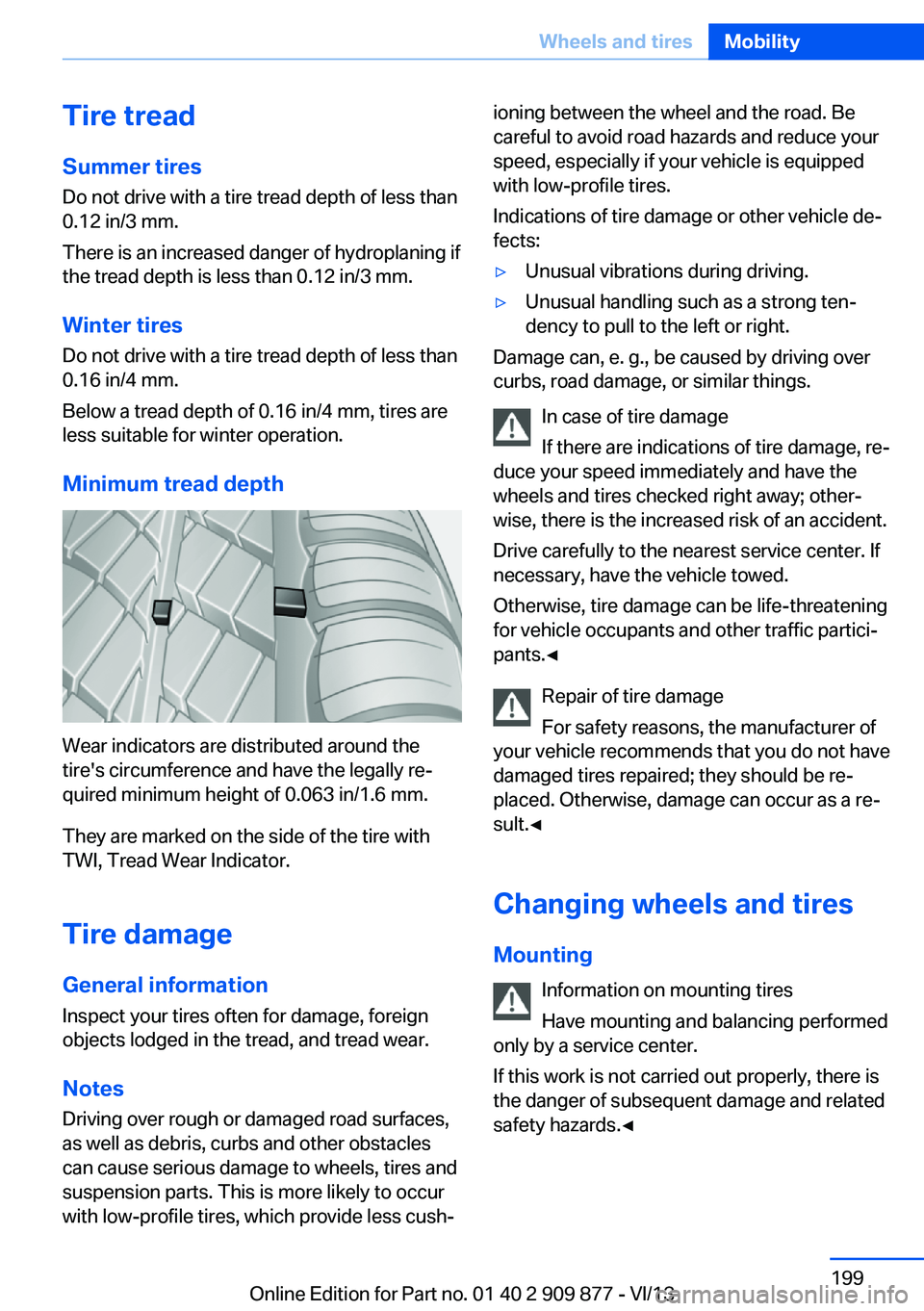
Minimum tread depth
Wear indicators are distributed around the
tire's circumference and have the legally re‐
quired minimum height of 0.063 in/1.6 mm.
They are marked on the side of the tire with
TWI, Tread Wear Indicator.
Tire damage
General information
Inspect your tires often for damage, foreign
objects lodged in the tread, and tread wear.
Notes
Driving over rough or damaged road surfaces,
as well as debris, curbs and other obstacles can cause serious damage to wheels, tires and
suspension parts. This is more likely to occur
with low-profile tires, which provide less cush‐
ioning between the wheel and the road. Be
careful to avoid road hazards and reduce your
speed, especially if your vehicle is equipped
with low-profile tires.
Indications of tire damage or other vehicle de‐
fects:▷Unusual vibrations during driving.▷Unusual handling such as a strong ten‐
dency to pull to the left or right.
Damage can, e. g., be caused by driving over
curbs, road damage, or similar things.
In case of tire damage
If there are indications of tire damage, re‐
duce your speed immediately and have the
wheels and tires checked right away; other‐
wise, there is the increased risk of an accident.
Drive carefully to the nearest service center. If
necessary, have the vehicle towed.
Otherwise, tire damage can be life-threatening
for vehicle occupants and other traffic partici‐
pants.◀
Repair of tire damage
For safety reasons, the manufacturer of
your vehicle recommends that you do not have
damaged tires repaired; they should be re‐
placed. Otherwise, damage can occur as a re‐
sult.◀
Changing wheels and tires
Mounting Information on mounting tires
Have mounting and balancing performed
only by a service center.
If this work is not carried out properly, there is
the danger of subsequent damage and related
safety hazards.◀
Seite 199Wheels and tiresMobility199
Online Edition for Part no. 01 40 2 909 877 - VI/13
Page 204 of 243
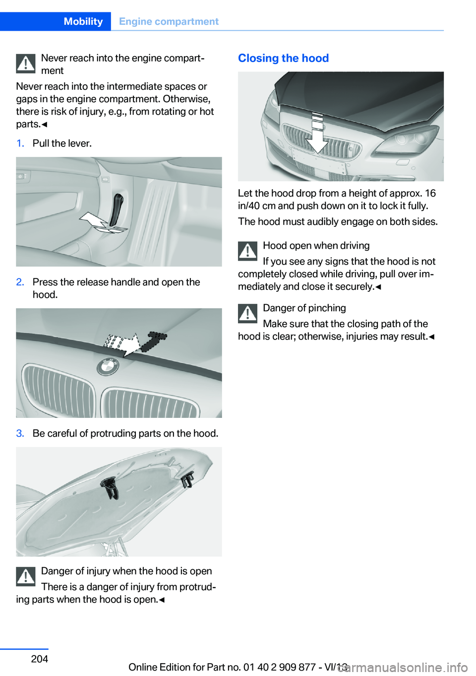
Never reach into the engine compart‐
ment
Never reach into the intermediate spaces or
gaps in the engine compartment. Otherwise,
there is risk of injury, e.g., from rotating or hot
parts.◀1.Pull the lever.2.Press the release handle and open the
hood.3.Be careful of protruding parts on the hood.
Danger of injury when the hood is open
There is a danger of injury from protrud‐
ing parts when the hood is open.◀
Closing the hood
Let the hood drop from a height of approx. 16
in/40 cm and push down on it to lock it fully.
The hood must audibly engage on both sides.
Hood open when driving
If you see any signs that the hood is not
completely closed while driving, pull over im‐
mediately and close it securely.◀
Danger of pinching
Make sure that the closing path of the
hood is clear; otherwise, injuries may result.◀
Seite 204MobilityEngine compartment204
Online Edition for Part no. 01 40 2 909 877 - VI/13
Page 218 of 243
Do not touch live parts
To avoid the risk of potentially fatal in‐
jury, always avoid all contact with electrical
components while the engine is running.◀
Preparation1.Check whether the battery of the other ve‐
hicle has a voltage of 12 volts. This infor‐
mation can be found on the battery.2.Switch off the engine of the assisting vehi‐
cle.3.Switch off any electronic systems/power
consumers in both vehicles.
Bodywork contact between vehicles
Make sure that there is no contact be‐
tween the bodywork of the two vehicles; other‐
wise, there is the danger of short circuits.◀
Starting aid terminals Connecting order
Connect the jumper cables in the correct
order; otherwise, there is the danger of injury
from sparking.◀
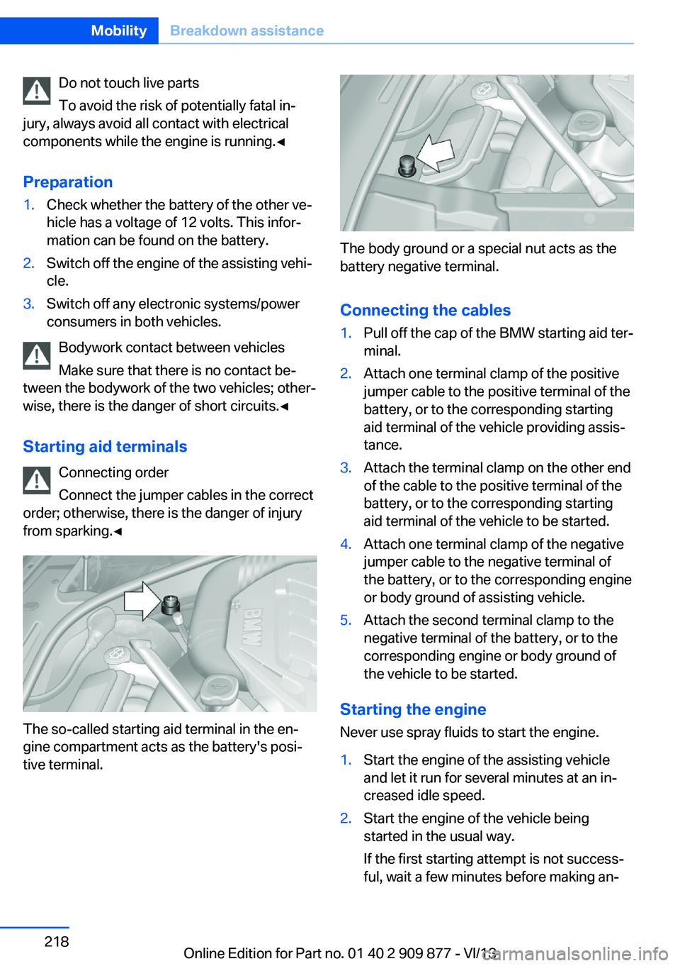
The so-called starting aid terminal in the en‐
gine compartment acts as the battery's posi‐
tive terminal.
The body ground or a special nut acts as the
battery negative terminal.
Connecting the cables
1.Pull off the cap of the BMW starting aid ter‐
minal.2.Attach one terminal clamp of the positive
jumper cable to the positive terminal of the
battery, or to the corresponding starting
aid terminal of the vehicle providing assis‐
tance.3.Attach the terminal clamp on the other end
of the cable to the positive terminal of the
battery, or to the corresponding starting
aid terminal of the vehicle to be started.4.Attach one terminal clamp of the negative
jumper cable to the negative terminal of
the battery, or to the corresponding engine
or body ground of assisting vehicle.5.Attach the second terminal clamp to the
negative terminal of the battery, or to the
corresponding engine or body ground of
the vehicle to be started.
Starting the engine
Never use spray fluids to start the engine.
1.Start the engine of the assisting vehicle
and let it run for several minutes at an in‐
creased idle speed.2.Start the engine of the vehicle being
started in the usual way.
If the first starting attempt is not success‐
ful, wait a few minutes before making an‐Seite 218MobilityBreakdown assistance218
Online Edition for Part no. 01 40 2 909 877 - VI/13