reset BMW 650I 2012 F12 Owner's Manual
[x] Cancel search | Manufacturer: BMW, Model Year: 2012, Model line: 650I, Model: BMW 650I 2012 F12Pages: 282, PDF Size: 8.25 MB
Page 14 of 282
Instrument cluster
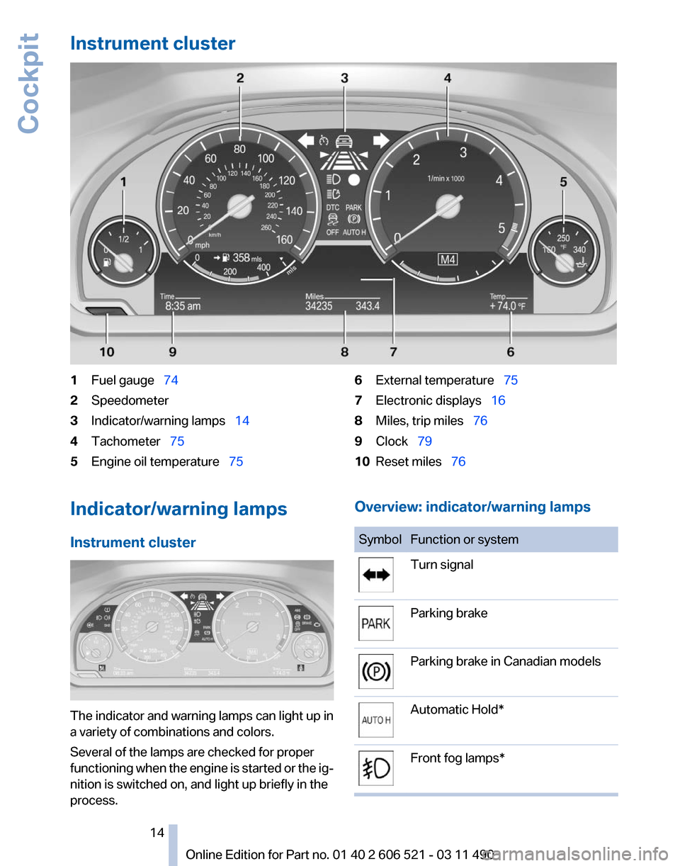
1
Fuel gauge 74
2 Speedometer
3 Indicator/warning lamps 14
4 Tachometer 75
5 Engine oil temperature 756
External temperature 75
7 Electronic displays 16
8 Miles, trip miles 76
9 Clock 79
10 Reset miles 76
Indicator/warning lamps
Instrument cluster The indicator and warning lamps can light up in
a variety of combinations and colors.
Several of the lamps are checked for proper
functioning
when the engine is started or the ig‐
nition is switched on, and light up briefly in the
process. Overview: indicator/warning lamps Symbol Function or system
Turn signal
Parking brake
Parking brake in Canadian models
Automatic Hold*
Front fog lamps* Seite 14
14 Online Edition for Part no. 01 40 2 606 521 - 03 11 490
Cockpit
Page 34 of 282
2.
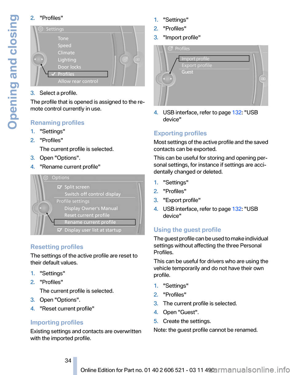
"Profiles" 3.
Select a profile.
The profile that is opened is assigned to the re‐
mote control currently in use.
Renaming profiles
1. "Settings"
2. "Profiles"
The current profile is selected.
3. Open "Options".
4. "Rename current profile" Resetting profiles
The settings of the active profile are reset to
their default values.
1.
"Settings"
2. "Profiles"
The current profile is selected.
3. Open "Options".
4. "Reset current profile"
Importing profiles
Existing settings and contacts are overwritten
with the imported profile. 1.
"Settings"
2. "Profiles"
3. "Import profile" 4.
USB interface, refer to page 132: "USB
device"
Exporting profiles
Most settings of the active profile and the saved
contacts can be exported.
This can be useful for storing and opening per‐
sonal settings, for instance if settings are acci‐
dentally changed or deleted.
1. "Settings"
2. "Profiles"
3. "Export profile"
4. USB interface, refer to page 132: "USB
device"
Using the guest profile
The
guest profile can be used to make individual
settings without affecting the three Personal
Profiles.
This can be useful for drivers who are using the
vehicle temporarily and do not have their own
profile.
1. "Settings"
2. "Profiles"
3. The current profile is selected.
4. Open "Guest".
5. Create the settings.
Note: the guest profile cannot be renamed.
Seite 34
34 Online Edition for Part no. 01 40 2 606 521 - 03 11 490
Opening and closing
Page 74 of 282
Displays
Instrument cluster
At a glance
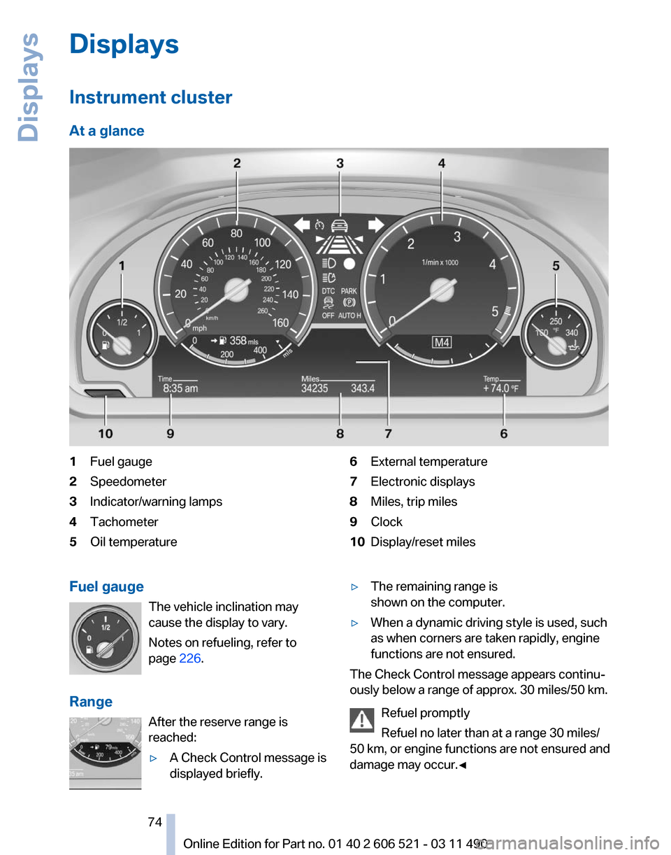
1
Fuel gauge
2 Speedometer
3 Indicator/warning lamps
4 Tachometer
5 Oil temperature 6
External temperature
7 Electronic displays
8 Miles, trip miles
9 Clock
10 Display/reset miles
Fuel gauge The vehicle inclination may
cause the display to vary.
Notes on refueling, refer to
page 226.
Range After the reserve range is
reached:
▷A Check Control message is
displayed briefly. ▷
The remaining range is
shown on the computer.
▷ When a dynamic driving style is used, such
as when corners are taken rapidly, engine
functions are not ensured.
The Check Control message appears continu‐
ously below a range of approx. 30 miles/50 km.
Refuel promptly
Refuel no later than at a range 30 miles/
50
km, or engine functions are not ensured and
damage may occur.◀ Seite 74
74 Online Edition for Part no. 01 40 2 606 521 - 03 11 490
Displays
Page 76 of 282
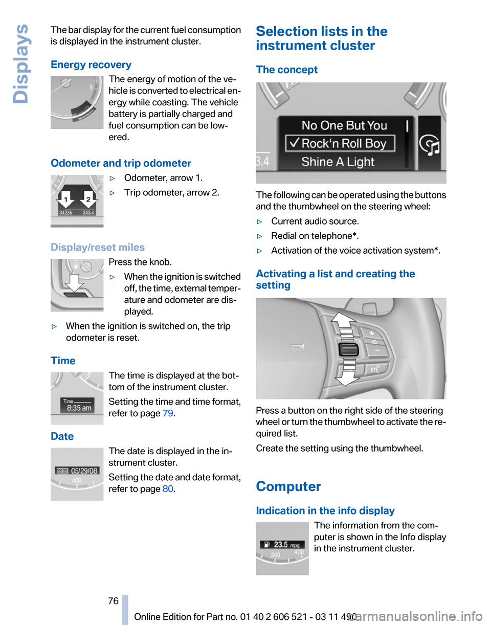
The bar display for the current fuel consumption
is displayed in the instrument cluster.
Energy recovery
The energy of motion of the ve‐
hicle
is converted to electrical en‐
ergy while coasting. The vehicle
battery is partially charged and
fuel consumption can be low‐
ered.
Odometer and trip odometer ▷Odometer, arrow 1.
▷ Trip odometer, arrow 2.
Display/reset miles Press the knob.
▷When the ignition is switched
off,
the time, external temper‐
ature and odometer are dis‐
played.
▷ When the ignition is switched on, the trip
odometer is reset.
Time The time is displayed at the bot‐
tom of the instrument cluster.
Setting
the time and time format,
refer to page 79.
Date The date is displayed in the in‐
strument cluster.
Setting the date and date format,
refer to page 80. Selection lists in the
instrument cluster
The concept
The following can be operated using the buttons
and the thumbwheel on the steering wheel:
▷
Current audio source.
▷ Redial on telephone*.
▷ Activation of the voice activation system*.
Activating a list and creating the
setting Press a button on the right side of the steering
wheel
or turn the thumbwheel to activate the re‐
quired list.
Create the setting using the thumbwheel.
Computer
Indication in the info display
The information from the com‐
puter is shown in the Info display
in the instrument cluster. Seite 76
76 Online Edition for Part no. 01 40 2 606 521 - 03 11 490
Displays
Page 77 of 282
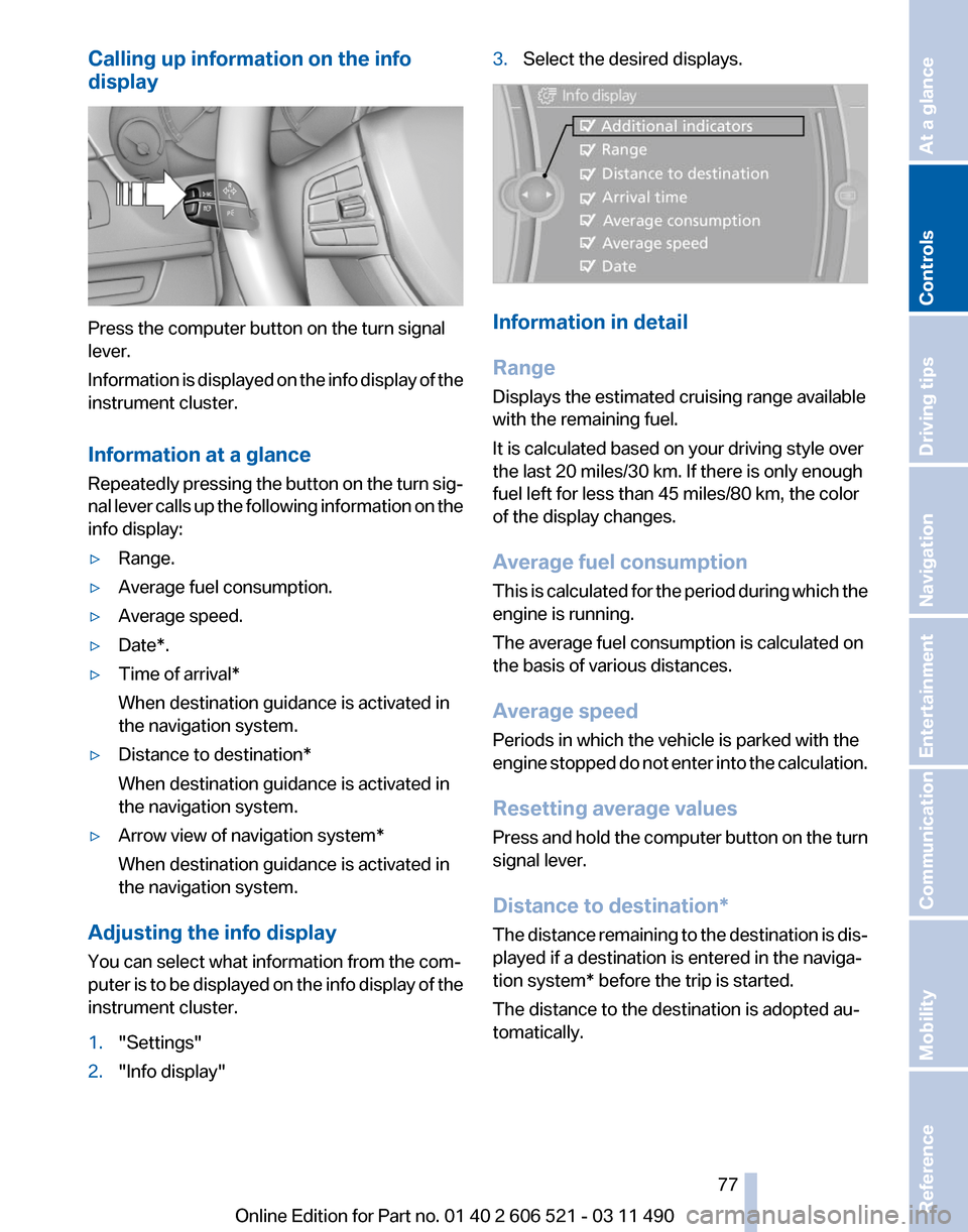
Calling up information on the info
display
Press the computer button on the turn signal
lever.
Information
is displayed on the info display of the
instrument cluster.
Information at a glance
Repeatedly pressing the button on the turn sig‐
nal lever calls up the following information on the
info display:
▷ Range.
▷ Average fuel consumption.
▷ Average speed.
▷ Date*.
▷ Time of arrival*
When destination guidance is activated in
the navigation system.
▷ Distance to destination*
When destination guidance is activated in
the navigation system.
▷ Arrow view of navigation system*
When destination guidance is activated in
the navigation system.
Adjusting the info display
You can select what information from the com‐
puter
is to be displayed on the info display of the
instrument cluster.
1. "Settings"
2. "Info display" 3.
Select the desired displays. Information in detail
Range
Displays the estimated cruising range available
with the remaining fuel.
It is calculated based on your driving style over
the last 20 miles/30 km. If there is only enough
fuel left for less than 45 miles/80 km, the color
of the display changes.
Average fuel consumption
This
is calculated for the period during which the
engine is running.
The average fuel consumption is calculated on
the basis of various distances.
Average speed
Periods in which the vehicle is parked with the
engine stopped do not enter into the calculation.
Resetting average values
Press and hold the computer button on the turn
signal lever.
Distance to destination*
The distance remaining to the destination is dis‐
played if a destination is entered in the naviga‐
tion system* before the trip is started.
The distance to the destination is adopted au‐
tomatically.
Seite 77
77Online Edition for Part no. 01 40 2 606 521 - 03 11 490
Reference Mobility Communication Entertainment Navigation Driving tips
Controls At a glance
Page 78 of 282
Time of arrival*
The estimated time of arrival is
displayed if a destination is en‐
tered in the navigation system
*
before the trip is started.
The time must be correctly set.
Speed limit
Display of a speed limit which, when reached,
should cause a warning to be issued.
Renewed warning if the vehicle speed drops be‐
low the set speed limit once by at least 3 mph/
5 km/h.
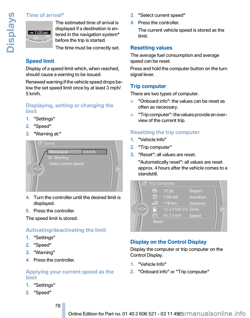
Displaying, setting or changing the
limit
1. "Settings"
2. "Speed"
3. "Warning at:" 4.
Turn the controller until the desired limit is
displayed.
5. Press the controller.
The speed limit is stored.
Activating/deactivating the limit
1. "Settings"
2. "Speed"
3. "Warning"
4. Press the controller.
Applying your current speed as the
limit
1. "Settings"
2. "Speed" 3.
"Select current speed"
4. Press the controller.
The current vehicle speed is stored as the
limit.
Resetting values
The average fuel consumption and average
speed can be reset.
Press
and hold the computer button on the turn
signal lever.
Trip computer
There are two types of computer.
▷ "Onboard info": the values can be reset as
often as necessary.
▷ "Trip
computer": the values provide an over‐
view of the current trip.
Resetting the trip computer
1. "Vehicle Info"
2. "Trip computer"
3. "Reset": all values are reset.
"Automatically reset": all values are reset
approx.
4 hours after the vehicle comes to a
standstill. Display on the Control Display
Display the computer or trip computer on the
Control Display.
1.
"Vehicle Info"
2. "Onboard info" or "Trip computer"
Seite 78
78 Online Edition for Part no. 01 40 2 606 521 - 03 11 490
Displays
Page 79 of 282
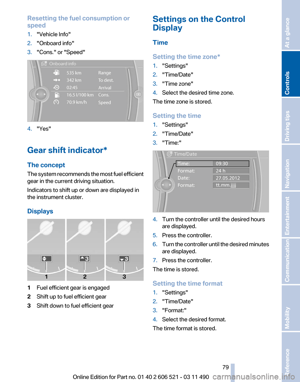
Resetting the fuel consumption or
speed
1.
"Vehicle Info"
2. "Onboard info"
3. "Cons." or "Speed" 4.
"Yes"
Gear shift indicator*
The concept
The
system recommends the most fuel efficient
gear in the current driving situation.
Indicators to shift up or down are displayed in
the instrument cluster.
Displays 1
Fuel efficient gear is engaged
2 Shift up to fuel efficient gear
3 Shift down to fuel efficient gear Settings on the Control
Display
Time
Setting the time zone
*
1. "Settings"
2. "Time/Date"
3. "Time zone"
4. Select the desired time zone.
The time zone is stored.
Setting the time
1. "Settings"
2. "Time/Date"
3. "Time:" 4.
Turn the controller until the desired hours
are displayed.
5. Press the controller.
6. Turn the controller until the desired minutes
are displayed.
7. Press the controller.
The time is stored.
Setting the time format
1. "Settings"
2. "Time/Date"
3. "Format:"
4. Select the desired format.
The time format is stored.
Seite 79
79Online Edition for Part no. 01 40 2 606 521 - 03 11 490
Reference Mobility Communication Entertainment Navigation Driving tips
Controls At a glance
Page 91 of 282
Rollover protection system
The concept
The
rollover protection system is activated dur‐
ing an accident or a critical driving situation,
when there is extreme tilt with respect to the
longitudinal axis or when there is loss of ground
contact. The safety frames located behind the
rear headrests extend within fractions of a sec‐
ond.
In addition to the rollover bracket integrated in
the front windshield frame, the rollover protec‐
tion system guarantees the required head clear‐
ance of all vehicle occupants.
Maintaining movement space
Always keep the movement space of the
rollover protection system clear. Otherwise,
there may be damage or injuries when the roll‐
over protection system is triggered.◀
In less severe accidents, the secured safety belt
and, depending on the severity of the accident,
the belt tensioner and airbag restraint system
provide protection.
Triggered rollover protection system
After deployment or damage
After deployment of the rollover protec‐
tion system or in the event of damage, have the
system checked and replaced.
Have this work performed only by your service
center; otherwise, it cannot be ensured that this
safety feature will function properly.◀
Do not move convertible top
When the rollover protection system is ex‐
tended, do not move the convertible top. Oth‐
erwise, damages or injuries may result.◀
If the rollover protection system was not placed
under any stress after an automatic triggering, it
can be pushed back by hand, e.g. to close the
convertible top. Three people are necessary for
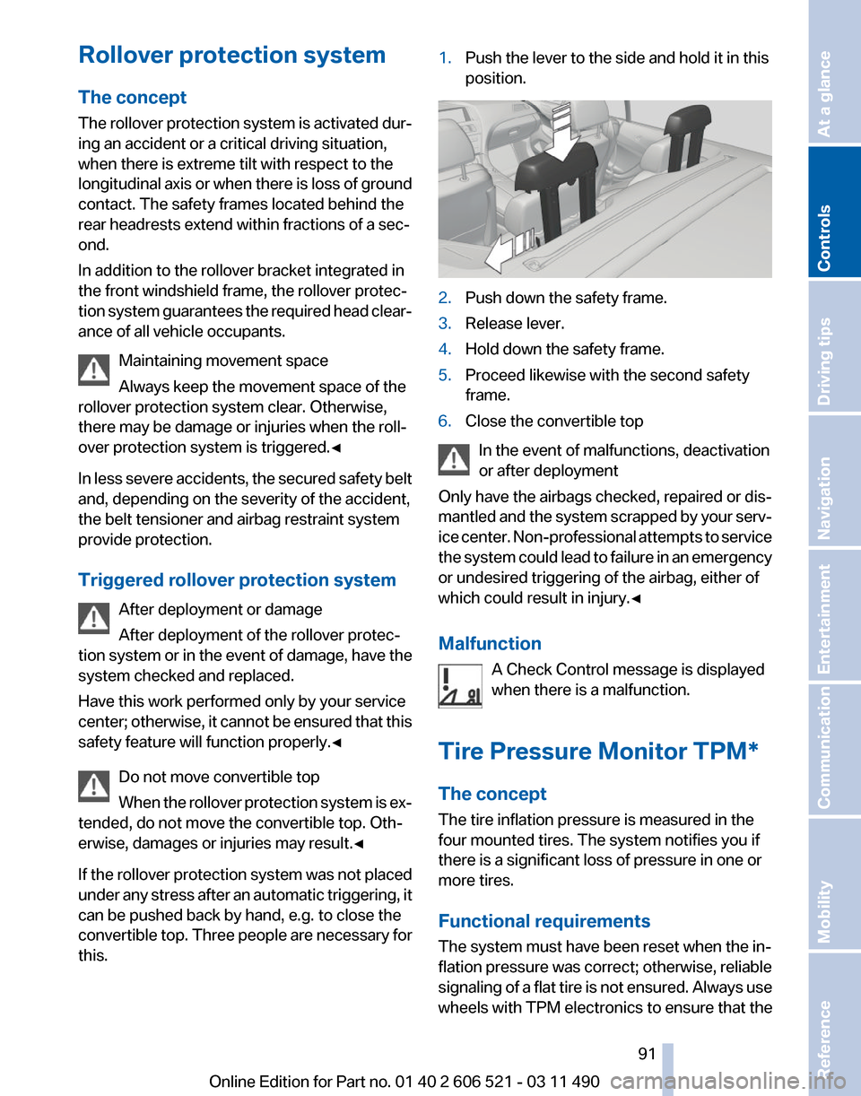
this. 1.
Push the lever to the side and hold it in this
position. 2.
Push down the safety frame.
3. Release lever.
4. Hold down the safety frame.
5. Proceed likewise with the second safety
frame.
6. Close the convertible top
In the event of malfunctions, deactivation
or after deployment
Only have the airbags checked, repaired or dis‐
mantled
and the system scrapped by your serv‐
ice center. Non-professional attempts to service
the system could lead to failure in an emergency
or undesired triggering of the airbag, either of
which could result in injury.◀
Malfunction
A Check Control message is displayed
when there is a malfunction.
Tire Pressure Monitor TPM*
The concept
The tire inflation pressure is measured in the
four mounted tires. The system notifies you if
there is a significant loss of pressure in one or
more tires.
Functional requirements
The system must have been reset when the in‐
flation pressure was correct; otherwise, reliable
signaling of a flat tire is not ensured. Always use
wheels with TPM electronics to ensure that the Seite 91
91Online Edition for Part no. 01 40 2 606 521 - 03 11 490
Reference Mobility Communication Entertainment Navigation Driving tips
Controls At a glance
Page 92 of 282
system will operate properly. Reset the system
after each correction of the tire inflation pres‐
sure and after every tire or wheel change.
System limits
Sudden tire damage
Sudden serious tire damage caused by
external influences cannot be indicated in ad‐
vance.◀
The system does not operate correctly if it has
not been reset. For example, a flat tire may be
indicated despite correct tire inflation pres‐
sures.
The
system is inactive and cannot indicate a flat
tire:
▷ For a mounted wheel without TPM electron‐
ics.
▷ When the TPM is disturbed by other sys‐
tems or devices with the same radio fre‐
quency.
Status display
The
current status of the Tire Pressure Monitor
TPM can be displayed on the Control Display,
e.g., whether or not the TPM is active.
1. "Vehicle Info"
2. "Vehicle status"
3. "Tire Pressure Monitor - TPM"
The status is displayed.
Status display
The tire and system status is indicated by the
color of the tires.
A change in the tire inflation pressure during
driving is taken into account.
A
correction is only necessary if this is indicated
by the TPM
Wheels, green
The tire inflation pressure is equal to the target
state. One wheel is yellow
A flat tire or major drop in inflation pressure in
the indicated tire.
All wheels are yellow
▷
A flat tire or major drop in inflation pressure
in several tires.
▷ The system was not reset after a wheel
change and thus warns based on the infla‐
tion pressures initialized last.
▷ A flat tire in one or more tires while the sys‐
tem is being reset.
Wheels, gray
The
system cannot detect a flat tire. Reasons for
this may be:
▷ TPM is being reset.
▷ Disturbance by systems or devices with the
same radio frequency.
▷ Malfunction.
For Canadian models: additional
information
The status display additionally shows the cur‐
rent tire inflation pressures and tire tempera‐
tures.
When correcting the tire inflation pressures,
note the following:
The tire pressure increases as the tire temper‐
ature increases.
Therefore, only correct the tire inflation pres‐
sure
when the tire is at the ambient temperature.
Compare the displayed tire temperature with
the external temperature in the instrument clus‐
ter.
Resetting the system
Reset the system after each correction of the
tire inflation pressure and after every tire or
wheel change.
1. "Vehicle Info"
2. "Vehicle status"
3. "Reset"
Seite 92
92 Online Edition for Part no. 01 40 2 606 521 - 03 11 490
Safety
Page 93 of 282
4.
Start the engine - do not drive away.
5. Reset the tire pressure using "Reset".
6. Drive away.
The tires are shown in gray and "Resetting
TPM..." is displayed.
After
driving for a few minutes, the set tire infla‐
tion pressures are applied as set values. The re‐
setting process is completed automatically dur‐
ing driving. The tires are shown in green and
"TPM active" is shown on the Control Display.
The trip can be interrupted at any time. If you
drive away again, the process resumes auto‐
matically.
If a flat tire is detected during a reset, all tires are
displayed in yellow.
Low tire pressure message
The yellow warning lamp lights up. A
Check Control message is displayed.
▷There is a flat tire or a major loss in
tire inflation pressure.
▷ The system was not reset after a wheel
change and thus warns based on the infla‐
tion pressures initialized last.
1. Reduce your speed and stop cautiously.
Avoid sudden braking and steering maneu‐
vers.
2. Check whether the vehicle is fitted with reg‐
ular tires* or run-flat tires*.
Run-flat
tires, refer to page 234, are labeled
with a circular symbol containing the letters
RSC marked on the tire sidewall.
When a low inflation pressure is indicated, DSC
Dynamic
Stability Control is switched on if nec‐
essary.
Actions in the event of a flat tire
Normal tires*
1. Identify the damaged tire.
Do this by checking the air pressure in all
four tires.
If the tire inflation pressure in all four tires is
correct, the Tire Pressure Monitor may not have been initialized. In this case, initialize
the system.
If an identification is not possible, please
contact the service center.
2. Rectify the flat tire.
Use
of tire sealant, e.g., the Mobility System,
may damage the TPM wheel electronics. In
this case, have the electronics checked at
the next opportunity and have them re‐
placed if necessary.
Run-flat tires*
You
can continue driving with a damaged tire at
speeds up to 50 mph/80 km/h.
Do not continue driving without run-flat
tires
Do not continue driving if the vehicle is not
equipped with run-flat tires; continued driving
may result in serious accidents.◀
Continued driving with a flat tire
If continuing to drive with a damaged tire:
1. Avoid sudden braking and steering maneu‐
vers.
2. Do not exceed a speed of 50 mph/80 km/h.
3. Check the air pressure in all four tires at the
next opportunity.
If the tire inflation pressure in all four tires is
correct, the Flat Tire Monitor may not have
been initialized. In this case, initialize the
system.
If the tire inflation pressure in all four tires is
correct, the Tire Pressure Monitor may not
have been initialized. In this case, initialize
the system.
Possible driving distance with complete loss of
tire inflation pressure:
The possible driving distance after a loss of tire
inflation pressure depends on the cargo load
and the driving style and conditions.
For a vehicle containing an average load, the
possible driving distance is approx. 50 miles/
80 km. Seite 93
93Online Edition for Part no. 01 40 2 606 521 - 03 11 490
Reference Mobility Communication Entertainment Navigation Driving tips
Controls At a glance