brake light BMW 650I CONVERTIBLE 2013 User Guide
[x] Cancel search | Manufacturer: BMW, Model Year: 2013, Model line: 650I CONVERTIBLE, Model: BMW 650I CONVERTIBLE 2013Pages: 240, PDF Size: 9.64 MB
Page 118 of 240
Driving stability control systemsVehicle equipment
All standard, country-specific and optional
equipment that is offered in the model series is
described in this chapter. Therefore, equipment
is also described that is not available in a vehicle,
e. g., because of the selected optional equip‐
ment or country variant. This also applies for
safety-related functions and systems.
Antilock Brake System ABS
ABS prevents locking of the wheels during brak‐
ing.
The vehicle remains steerable even during full
brake applications, thus increasing active
safety.
ABS is operational every time you start the en‐
gine.
Brake assistant
When you apply the brakes rapidly, this system
automatically produces the maximum braking
force boost. It thus helps to achieve the shortest
possible braking distance during full braking.
This system utilizes all of the benefits provided
by ABS.
Do not reduce the pressure on the brake pedal
for the duration of the full braking.
Adaptive brake assistant
In combination with the Active Cruise Control,
this system ensures that the brakes respond
even more rapidly when braking in critical situa‐
tions. Refer also to Collision warning, refer to
page 109.Drive-off assistant
This system supports driving away on gradients.
The parking brake is not required.1.Hold the vehicle in place with the foot brake.2.Release the foot brake and drive away with‐
out delay.
After the foot brake is released, the vehicle is
held in place for approx. 2 seconds.
Depending on the vehicle load, the vehicle may
roll back slightly.
Driving off without delay
After releasing the foot brake, start driving
without delay, since the drive-off assistant will
not hold the vehicle in place for more than ap‐
prox. 2 seconds and the vehicle will begin rolling
back.◀
DSC Dynamic Stability
Control
The concept
DSC prevents traction loss in the driving wheels
when driving away and accelerating.
DSC also recognizes unstable vehicle condi‐
tions, such as fishtailing or nose-diving. Subject
to physical limits, DSC helps to keep the vehicle
on a steady course by reducing engine speed
and by applying brakes at individual wheels.
Adjust your driving style to the situation
An appropriate driving style is always the
responsibility of the driver.
The laws of physics cannot be repealed, even
with DSC.
Therefore, do not reduce the additional safety
margin by driving in a risky manner.◀
Seite 118ControlsDriving stability control systems118
Online Edition for Part no. 01 40 2 903 169 - 07 12 490
Page 119 of 240
Indicator/warning lampsThe indicator lamp flashes: DSC con‐
trols the drive forces and brake forces.
The indicator lamp lights up: DSC has
failed.
Deactivating DSC: DSC OFF
When DSC is deactivated, driving stability is re‐
duced during acceleration and when driving in
bends.
Stabilizing interventions by the Integral Active
Steering system are only performed by the rear
axle steering.
To increase vehicle stability, activate DSC again
as soon as possible.
Deactivating DSC Press and hold the button, but not lon‐
ger than approx. 10 seconds, until the
indicator lamp for DSC OFF lights up in the in‐
strument cluster and DSC OFF is displayed.
The DSC system is switched off.
Activating DSC Press the button.
DSC OFF and the DSC OFF indicator
lamp go out.
Indicator/warning lamps
When DSC is deactivated, DSC OFF is dis‐
played in the instrument cluster.
The indicator lamp lights up: DSC is de‐
activated.DTC Dynamic Traction
Control
The concept
The DTC system is a version of the DSC in which
forward momentum is optimized.
The system ensures maximum forward momen‐
tum on special road conditions, e.g., unplowed
snowy roads, but driving stability is limited.
It is therefore necessary to drive with appropri‐
ate caution.
You may find it useful to briefly activate DTC un‐
der the following special circumstances:▷When driving in slush or on uncleared,
snow-covered roads.▷When rocking the vehicle or driving off in
deep snow or on loose surfaces.▷When driving with snow chains.
Deactivating/activating DTC Dynamic
Traction Control
Activating the Dynamic Traction Control DTC
provides maximum traction on loose ground.
Driving stability is limited during acceleration
and when driving in bends.
Activating DTC Press the button.
TRACTION is displayed in the instru‐
ment cluster and the indicator lamp for DSC
OFF lights up.
Deactivating DTC Press the button again.
TRACTION and the DSC OFF indicator
lamp go out.
Indicator/warning lamps
When DTC is activated, TRACTION is displayed
in the tachometer.
Seite 119Driving stability control systemsControls119
Online Edition for Part no. 01 40 2 903 169 - 07 12 490
Page 120 of 240
The indicator lamp lights up: DTC Dy‐
namic Traction Control is activated.
xDrive
xDrive is the all-wheel-drive system of your ve‐
hicle. Concerted action by the xDrive and DSC
further optimize traction and driving dynamics.
The xDrive all-wheel-drive system variably dis‐
tributes the drive forces to the front and rear
axles as demanded by the driving situation and
road surface.
HDC Hill Descent Control
The concept
HDC is a downhill driving assistant that auto‐
matically controls vehicle speed on steep down‐
hill gradients. Without applying the brakes, the
vehicle moves at slightly more than walking
speed.
Hill Descent Control can be activated at speeds
below approx. 22 mph/35 km/h. When driving
downhill, the vehicle reduces its speed to ap‐
prox. walking speed and then keeps its speed
constant.
As long as there is active braking, the system is
on standby. The system does not brake the ve‐
hicle during this time.
Use HDC in low gears or in transmission position
D or R only.
Increasing or decreasing vehicle speed
Specify desired speed in the range from approx.
4 mph/6 km/h to approx. 15 mph/25 km/h using
the rocker switch of the cruise control on the
steering wheel. Vehicle speed can be changed
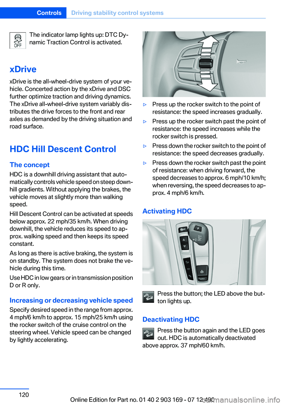
by lightly accelerating.▷Press up the rocker switch to the point of
resistance: the speed increases gradually.▷Press up the rocker switch past the point of
resistance: the speed increases while the
rocker switch is pressed.▷Press down the rocker switch to the point of
resistance: the speed decreases gradually.▷Press down the rocker switch past the point
of resistance: when driving forward, the
speed decreases to approx. 6 mph/10 km/h;
when reversing, the speed decreases to ap‐
prox. 4 mph/6 km/h.
Activating HDC
Press the button; the LED above the but‐
ton lights up.
Deactivating HDC Press the button again and the LED goes
out. HDC is automatically deactivated
above approx. 37 mph/60 km/h.
Seite 120ControlsDriving stability control systems120
Online Edition for Part no. 01 40 2 903 169 - 07 12 490
Page 126 of 240
Driving comfortVehicle equipment
All standard, country-specific and optional
equipment that is offered in the model series is
described in this chapter. Therefore, equipment
is also described that is not available in a vehicle,
e. g., because of the selected optional equip‐
ment or country variant. This also applies for
safety-related functions and systems.
Active Cruise Control with
Stop & Go function, ACC
The concept
This system can be used to select a desired
speed that the vehicle will maintain automati‐
cally on clear roads.
To the extent possible, the system automatically
adjusts the speed to a slower vehicle ahead of
you.
The distance that the vehicle maintains to the
vehicle ahead of you can be varied.
For safety reasons, it depends on the speed.
To maintain a certain distance, the system au‐
tomatically decelerates, applies the brakes
lightly, or accelerates again if the vehicle ahead
begins moving faster.
If the vehicle ahead of you brakes to a halt, the
system is able to detect this within the given
system limits. If the vehicle ahead of your drives
away again from a halt, your vehicle is able to
accelerate if operated accordingly.
Even if some time passes before the vehicle
drives away again, the BMW can still be accel‐
erated automatically and simply.
As soon as the road is clear, it accelerates to the
desired speed.
The speed is also maintained on downhill gra‐
dients, but may not be maintained on uphill
slopes if engine power is insufficient.General information
When ECO PRO is activated, cruise control is
also set to a driving style that saves on fuel con‐
sumption.
Notes Personal responsibility
The system does not relieve the driver of
the responsibility to adapt his or her speed, dis‐
tance and driving style to the traffic conditions.
You should drive attentively and intervene ac‐
tively when necessary, e.g. by braking or making
an evasive maneuver, otherwise, there is danger
of an accident.◀
At a glance
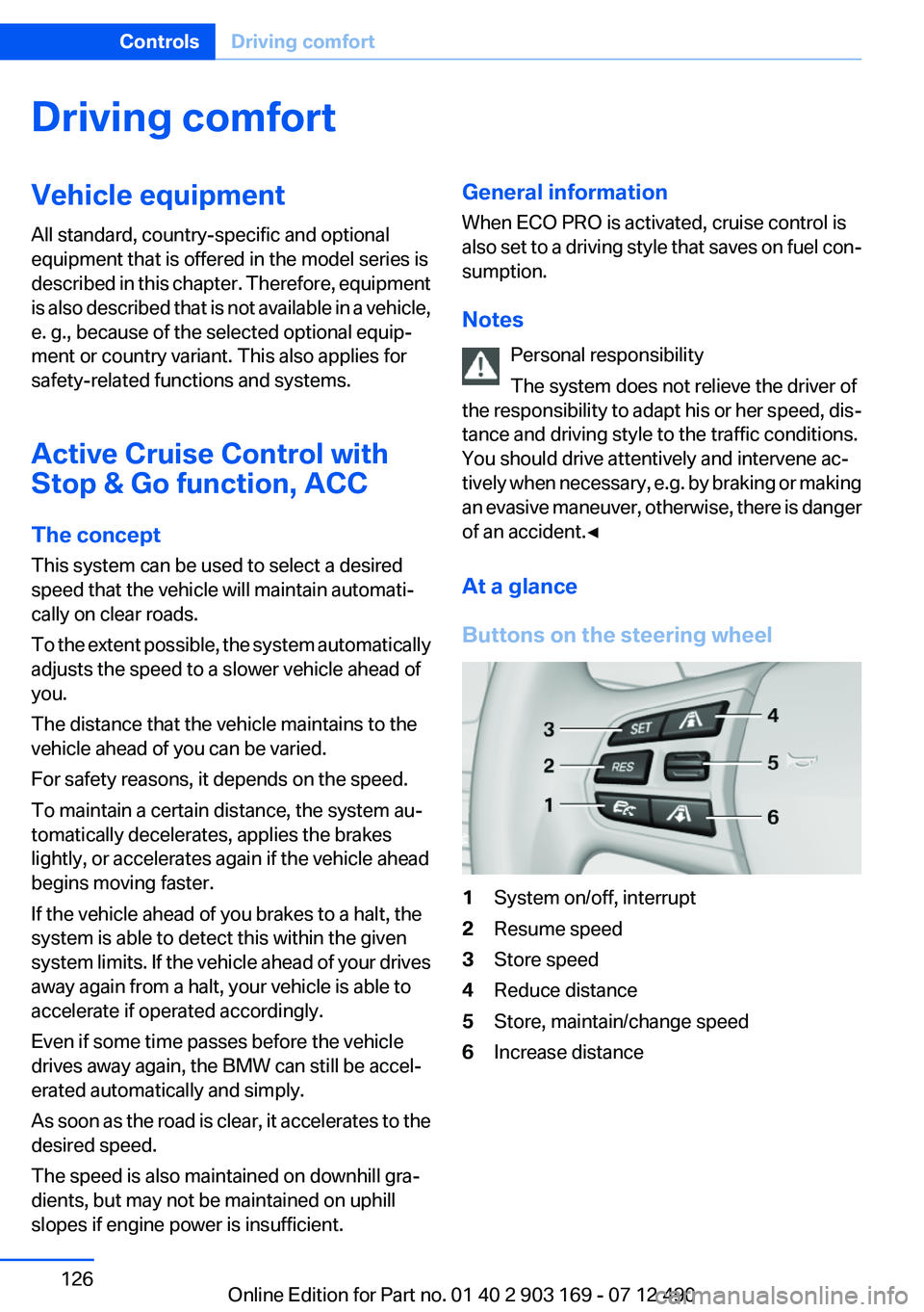
Buttons on the steering wheel1System on/off, interrupt2Resume speed3Store speed4Reduce distance5Store, maintain/change speed6Increase distanceSeite 126ControlsDriving comfort126
Online Edition for Part no. 01 40 2 903 169 - 07 12 490
Page 127 of 240
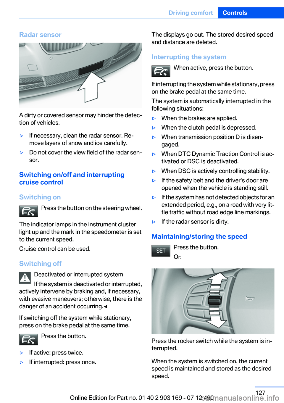
Radar sensor
A dirty or covered sensor may hinder the detec‐
tion of vehicles.
▷If necessary, clean the radar sensor. Re‐
move layers of snow and ice carefully.▷Do not cover the view field of the radar sen‐
sor.
Switching on/off and interrupting
cruise control
Switching on Press the button on the steering wheel.
The indicator lamps in the instrument cluster
light up and the mark in the speedometer is set
to the current speed.
Cruise control can be used.
Switching off Deactivated or interrupted system
If the system is deactivated or interrupted,
actively intervene by braking and, if necessary,
with evasive maneuvers; otherwise, there is the
danger of an accident occurring.◀
If switching off the system while stationary,
press on the brake pedal at the same time.
Press the button.
▷If active: press twice.▷If interrupted: press once.The displays go out. The stored desired speed
and distance are deleted.
Interrupting the system When active, press the button.
If interrupting the system while stationary, press
on the brake pedal at the same time.
The system is automatically interrupted in the
following situations:▷When the brakes are applied.▷When the clutch pedal is depressed.▷When transmission position D is disen‐
gaged.▷When DTC Dynamic Traction Control is ac‐
tivated or DSC is deactivated.▷When DSC is actively controlling stability.▷If the safety belt and the driver's door are
opened when the vehicle is standing still.▷If the system has not detected objects for an
extended period, e.g., on a road with very lit‐
tle traffic without road edge line markings.▷If the radar sensor is dirty.
Maintaining/storing the speed
Press the button.
Or:
Press the rocker switch while the system is in‐
terrupted.
When the system is switched on, the current
speed is maintained and stored as the desired
speed.
Seite 127Driving comfortControls127
Online Edition for Part no. 01 40 2 903 169 - 07 12 490
Page 129 of 240
While standingBefore leaving the vehicle, secure it
against rolling.
Before leaving the vehicle with the engine run‐
ning, engage position P of the automatic trans‐
mission and apply the parking brake. Otherwise,
the vehicle may begin to roll.◀
The system brought the vehicle to a complete
standstill.▷Green mark in the speedometer during a
brief idle phase:
The vehicle ahead of you drives away while
the mark is green: your vehicle accelerates
without anything having to be done.▷Switch to orange of the mark in the speed‐
ometer after approx. 2 sec.:
The vehicle ahead of you drives away, while
the mark is orange: in order to accelerate,
briefly press the gas pedal or press the RES
button or SET button.
Rolling bars in the distance indicator mean that
the vehicle ahead of you has driven off.
You actively braked your vehicle to a halt by
pressing on the brake pedal and it is standing
behind another vehicle:
1. Press the button to call up a stored
desired speed.2.Release the brake pedal.3.Press on the accelerator briefly, or press the
RES button or the rocker switch when the
vehicle ahead of you drives away.
Displays in the instrument cluster
Desired speed
▷The marking lights up green:
the system is active.▷The marking lights up or‐
ange: the system has been
interrupted.▷The marking does not light up: the system is
switched off.
With instrument display: the symbol is
displayed in the speedometer similarly
to the mark for the desired speed.
Brief status display Selected desired speed.
If --- appears briefly on the display for Check
Control messages, it is possible that the system
requirements for operation are currently not
met.
Distance to vehicle ahead of you
The selected distance to the vehicle driving
ahead of you is shown.
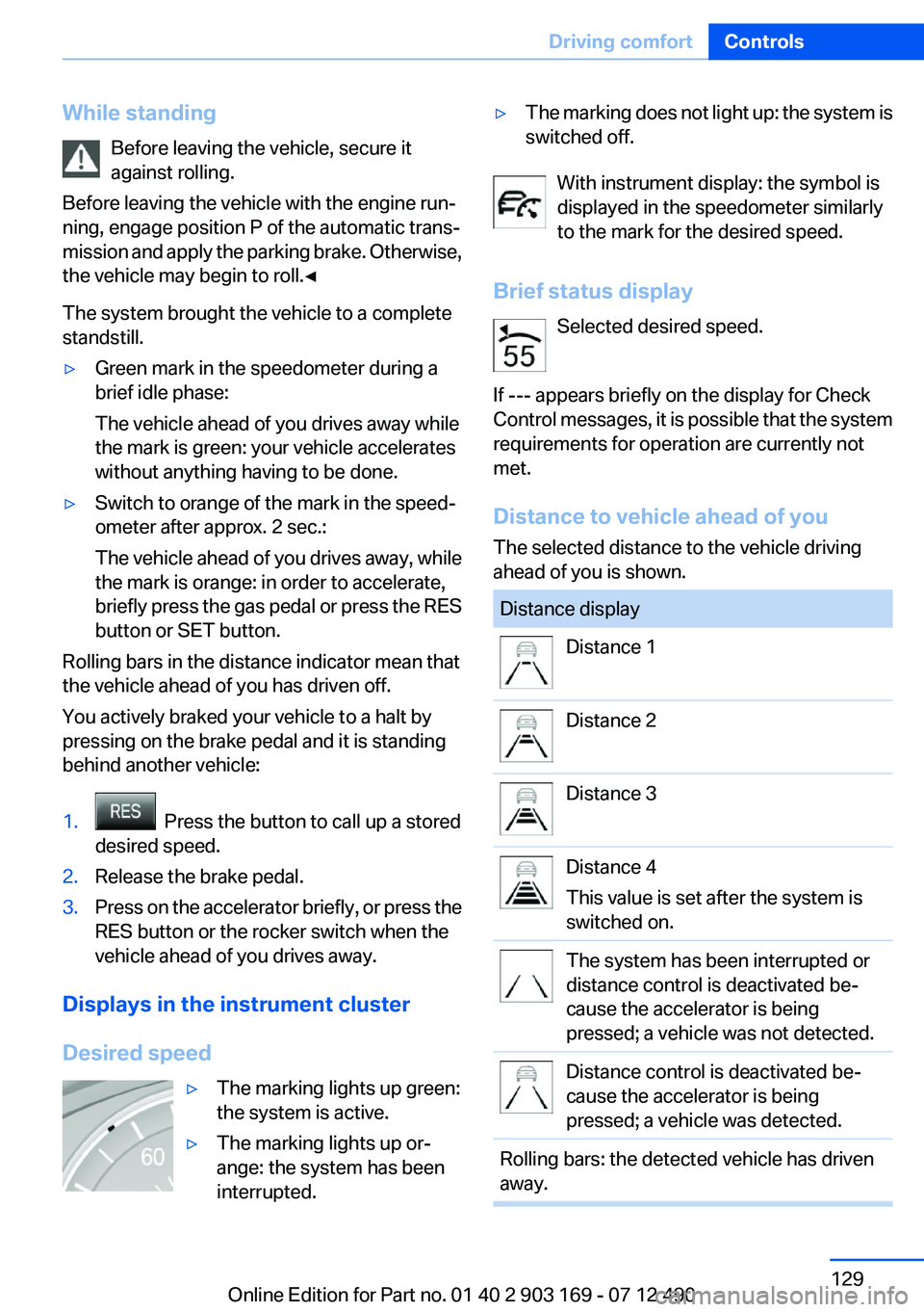
Distance displayDistance 1Distance 2Distance 3Distance 4
This value is set after the system is
switched on.The system has been interrupted or
distance control is deactivated be‐
cause the accelerator is being
pressed; a vehicle was not detected.Distance control is deactivated be‐
cause the accelerator is being
pressed; a vehicle was detected.Rolling bars: the detected vehicle has driven
away.Seite 129Driving comfortControls129
Online Edition for Part no. 01 40 2 903 169 - 07 12 490
Page 130 of 240
Indicator/warning lampsPersonal responsibility
The indicator and warning lamps do not
relieve the driver of the responsibility to adapt
his or her desired driving speed and style to the
traffic conditions.◀
The vehicle symbol lights up orange:
A vehicle has been detected ahead of
you.
The vehicle symbol flashes orange:
The conditions are not adequate for op‐
erating the system.
The system was deactivated but applies the
brakes until you actively assume control by
pressing on the brake pedal or accelerator.
The vehicle symbol flashes red and an
acoustic signal sounds:
You are requested to intervene by brak‐
ing or making an evasive maneuver.
Displays in the Head-up Display
The information from Active Cruise Control can
also be displayed in the Head-up Display.
Adjusting the Head-up Display, refer to
page 146.
System limits
Speed range
Best results are achieved when using the sys‐
tem on well-developed roads and highways.
The desired speed can be selected between
20 mph/30 km/h to 110 mph/180 km/h.
The system can also be activated when station‐
ary.
Comply with the legal speed limit in every situa‐
tion when using the system.Detection range
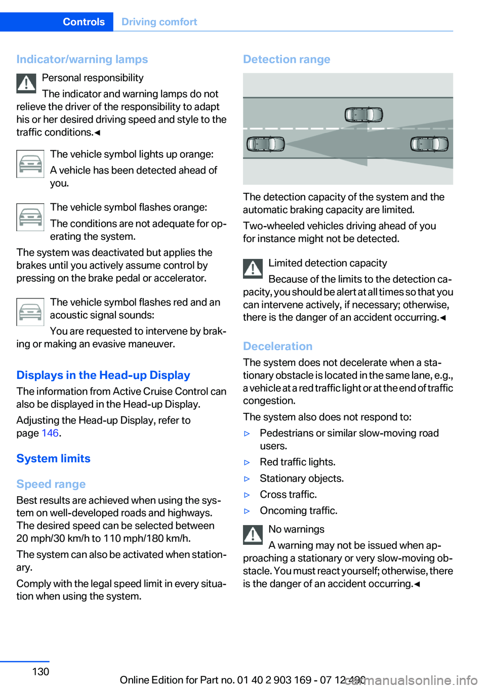
The detection capacity of the system and the
automatic braking capacity are limited.
Two-wheeled vehicles driving ahead of you
for instance might not be detected.
Limited detection capacity
Because of the limits to the detection ca‐
pacity, you should be alert at all times so that you
can intervene actively, if necessary; otherwise,
there is the danger of an accident occurring.◀
Deceleration
The system does not decelerate when a sta‐
tionary obstacle is located in the same lane, e.g.,
a vehicle at a red traffic light or at the end of traffic
congestion.
The system also does not respond to:
▷Pedestrians or similar slow-moving road
users.▷Red traffic lights.▷Stationary objects.▷Cross traffic.▷Oncoming traffic.
No warnings
A warning may not be issued when ap‐
proaching a stationary or very slow-moving ob‐
stacle. You must react yourself; otherwise, there
is the danger of an accident occurring.◀
Seite 130ControlsDriving comfort130
Online Edition for Part no. 01 40 2 903 169 - 07 12 490
Page 166 of 240
Objects in the area around the pedalsNo objects in the area around the pedals
Keep floor mats, carpets, and any other
objects out of the area of motion of the pedals;
otherwise, the function of the pedals could be
impeded while driving
Do not place additional floor mats over existing
mats or other objects.
Only use floor mats that have been approved for
the vehicle and can be properly fixed in place.
Ensure that the floor mats are securely fastened
again after they were removed for cleaning, for
example.◀
Driving in wet conditions
When roads are wet or there is heavy rain, briefly
exert gentle pressure on the brake pedal every
few miles.
Ensure that this action does not endanger other
road users.
The heat generated in this process helps dry the
brake discs and pads.
In this way braking efficiency will be available
when you need it.
Hills
Drive long or steep downhill gradients in the gear
in which the least braking is required. Otherwise,
the brake system may overheat, resulting in a
reduction in the brake system efficiency.
Manual transmission:
You can increase the engine's braking effect by
shifting down, going all the way to first gear, if
necessary.
Automatic transmission:
You can increase the engine's braking effect by
shifting down in the manual mode of the auto‐
matic transmission.Avoid load on the brakes
Avoid placing excessive load on the brake
system. Light but consistent brake pressure can
lead to high temperatures, brake wear and pos‐
sibly even brake failure.◀
Do not drive in neutral
Do not drive in neutral or with the engine
stopped, as doing so disables engine braking. In
addition, steering and brake assist is unavailable
with the engine stopped.◀
Brake disc corrosion
Corrosion on the brake discs and contamination
on the brake pads are furthered by:▷Low mileage.▷Extended periods when the vehicle is not
used at all.▷Infrequent use of the brakes.
Corrosion occurs when the minimum pressure
that must be exerted by the pads during brake
applications to clean the discs is not reached.
Should corrosion form on the brake discs, the
brakes will tend to respond with a pulsating ef‐
fect that generally cannot be corrected.
Condensation under the parked vehicle
When using the automatic climate control, con‐
densation water develops that exits underneath
the vehicle.
Therefore, traces of condensed water under the
vehicle are normal.
Seite 166Driving tipsThings to remember when driving166
Online Edition for Part no. 01 40 2 903 169 - 07 12 490
Page 196 of 240
Socket for OBD Onboard
Diagnosis
Position
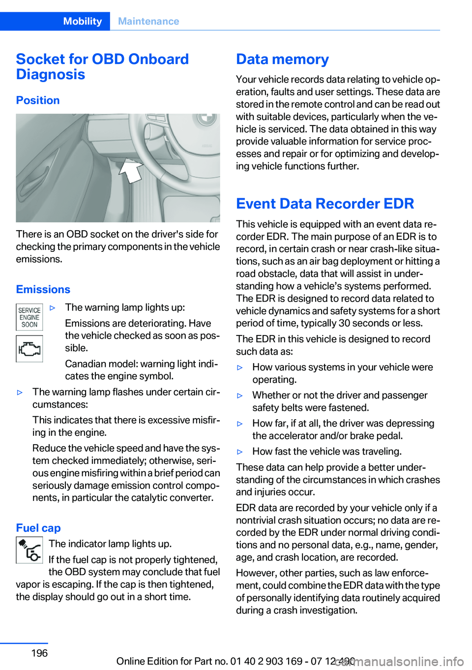
There is an OBD socket on the driver's side for
checking the primary components in the vehicle
emissions.
Emissions
▷The warning lamp lights up:
Emissions are deteriorating. Have
the vehicle checked as soon as pos‐
sible.
Canadian model: warning light indi‐
cates the engine symbol.▷The warning lamp flashes under certain cir‐
cumstances:
This indicates that there is excessive misfir‐
ing in the engine.
Reduce the vehicle speed and have the sys‐
tem checked immediately; otherwise, seri‐
ous engine misfiring within a brief period can
seriously damage emission control compo‐
nents, in particular the catalytic converter.
Fuel cap
The indicator lamp lights up.
If the fuel cap is not properly tightened,
the OBD system may conclude that fuel
vapor is escaping. If the cap is then tightened,
the display should go out in a short time.
Data memory
Your vehicle records data relating to vehicle op‐
eration, faults and user settings. These data are
stored in the remote control and can be read out
with suitable devices, particularly when the ve‐
hicle is serviced. The data obtained in this way
provide valuable information for service proc‐
esses and repair or for optimizing and develop‐
ing vehicle functions further.
Event Data Recorder EDR
This vehicle is equipped with an event data re‐
corder EDR. The main purpose of an EDR is to
record, in certain crash or near crash-like situa‐
tions, such as an air bag deployment or hitting a
road obstacle, data that will assist in under‐
standing how a vehicle’s systems performed.
The EDR is designed to record data related to
vehicle dynamics and safety systems for a short
period of time, typically 30 seconds or less.
The EDR in this vehicle is designed to record
such data as:▷How various systems in your vehicle were
operating.▷Whether or not the driver and passenger
safety belts were fastened.▷How far, if at all, the driver was depressing
the accelerator and/or brake pedal.▷How fast the vehicle was traveling.
These data can help provide a better under‐
standing of the circumstances in which crashes
and injuries occur.
EDR data are recorded by your vehicle only if a
nontrivial crash situation occurs; no data are re‐
corded by the EDR under normal driving condi‐
tions and no personal data, e.g., name, gender,
age, and crash location, are recorded.
However, other parties, such as law enforce‐
ment, could combine the EDR data with the type
of personally identifying data routinely acquired
during a crash investigation.
Seite 196MobilityMaintenance196
Online Edition for Part no. 01 40 2 903 169 - 07 12 490
Page 200 of 240
Turning lamp on the Xenon headlamp
Follow the general instructions on lamps and
bulbs, refer to page 198.
The illustration shows the left side of the engine
compartment.
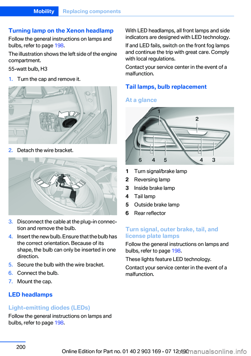
55-watt bulb, H31.Turn the cap and remove it.2.Detach the wire bracket.3.Disconnect the cable at the plug-in connec‐
tion and remove the bulb.4.Insert the new bulb. Ensure that the bulb has
the correct orientation. Because of its
shape, the bulb can only be inserted in one
direction.5.Secure the bulb with the wire bracket.6.Connect the bulb.7.Mount the cap.
LED headlamps
Light-emitting diodes (LEDs)
Follow the general instructions on lamps and
bulbs, refer to page 198.
With LED headlamps, all front lamps and side
indicators are designed with LED technology.
If and LED fails, switch on the front fog lamps
and continue the trip with great care. Comply
with local regulations.
Contact your service center in the event of a
malfunction.
Tail lamps, bulb replacement
At a glance1Turn signal/brake lamp2Reversing lamp3Inside brake lamp4Tail lamp5Outside brake lamp6Rear reflector
Turn signal, outer brake, tail, and
license plate lamps
Follow the general instructions on lamps and
bulbs, refer to page 198.
These lights feature LED technology.
Contact your service center in the event of a
malfunction.
Seite 200MobilityReplacing components200
Online Edition for Part no. 01 40 2 903 169 - 07 12 490