brake light BMW 650I GRAN COUPE 2016 Owner's Manual
[x] Cancel search | Manufacturer: BMW, Model Year: 2016, Model line: 650I GRAN COUPE, Model: BMW 650I GRAN COUPE 2016Pages: 255, PDF Size: 6.01 MB
Page 132 of 255
Driving stability control systemsVehicle features and optionsThis chapter describes all standard, country-
specific and optional features offered with the
series. It also describes features that are not
necessarily available in your car, e. g., due to
the selected options or country versions. This
also applies to safety-related functions and
systems. The respectively applicable country
provisions must be observed when using the
respective features and systems.
Antilock Brake System ABS ABS prevents locking of the wheels during
braking.
The vehicle contains its steering power even
during full brake applications, thus increasing
active safety.
ABS is operational every time you start the en‐
gine.
Brake assistant When you apply the brakes rapidly, this system
automatically produces the greatest possible
braking force boost. It reduces the braking dis‐
tance to a minimum during emergency stop.
This system utilizes all of the benefits provided
by ABS.
Do not reduce the pressure on the brake pedal
for the duration of the emergency stop.
Adaptive brake assistant In combination with the Active Cruise Control,
this system ensures that the brakes respond
even more rapidly when braking in critical sit‐
uations.Drive-off assistant
This system supports driving off on inclines.
The parking brake is not required.1.Hold the vehicle in place with the foot
brake.2.Release the foot brake and drive off with‐
out delay.
After the foot brake is released, the vehicle is
held in place for approx. 2 seconds.
Depending on the vehicle load, the vehicle may
roll back slightly.
Driving off without delay
After releasing the foot brake, start driv‐
ing without delay, since the drive-off assistant
will not hold the vehicle in place for more than
approx. 2 seconds and the vehicle will begin to
roll back.◀
DSC Dynamic Stability
Control
The concept DSC prevents traction loss in the power
wheels when driving off and accelerating.
DSC also recognizes unstable vehicle condi‐
tions such as fishtailing or nose-diving. Within
the physical limits DSC helps to keep the vehi‐
cle on a steady course by reducing engine
speed and by applying brakes to the individual
wheels.
Note Adjust your driving style to the situation
An appropriate driving style is always the
responsibility of the driver.
The laws of physics cannot be repealed, not
even with DSC.
Seite 128ControlsDriving stability control systems128
Online Edition for Part no. 01 40 2 954 231 - II/15
Page 134 of 255
▷When freeing vehicle from deep snow or
driving off from loose grounds.▷When driving with snow chains.
Deactivating/activating DTC Dynamic
Traction Control
Activating DTC Press button.
TRACTION is displayed in the instru‐
ment cluster and the indicator lamp for DSC
OFF lights up.
Deactivating DTC Press button again.
TRACTION and the DSC OFF indica‐
tor lamp go out.
Indicator/warning lights
If DTC is activated, TRACTION is displayed in
the instrument cluster.
The indicator lamp lights up: DTC Dy‐
namic Traction Control is activated.
xDrive xDrive is the all-wheel-drive system of your ve‐
hicle. Concerted action by the xDrive and DSC
further optimize traction and driving dynamics.
The xDrive all-wheel-drive system variably dis‐
tributes the drive forces to the front and rear
axles as demanded by the driving situation and
road surface.
HDC Hill Descent Control
The concept HDC is a downhill driving assistant that auto‐
matically controls vehicle speed on steep
downhill gradients. Without applying the
brakes, the vehicle moves at slightly more than
walking speed.
Hill Descent Control can be activated at
speeds below approx. 22 mph/35 km/h. When
driving downhill, the vehicle reduces its speed
to approx. walking speed and then keeps its
speed constant.
As long as there is active braking, the system
is on standby. The system does not brake the
vehicle during this time.
Only use HDC in low gears or in selector lever
position D or R.
Increasing or decreasing vehicle
speed
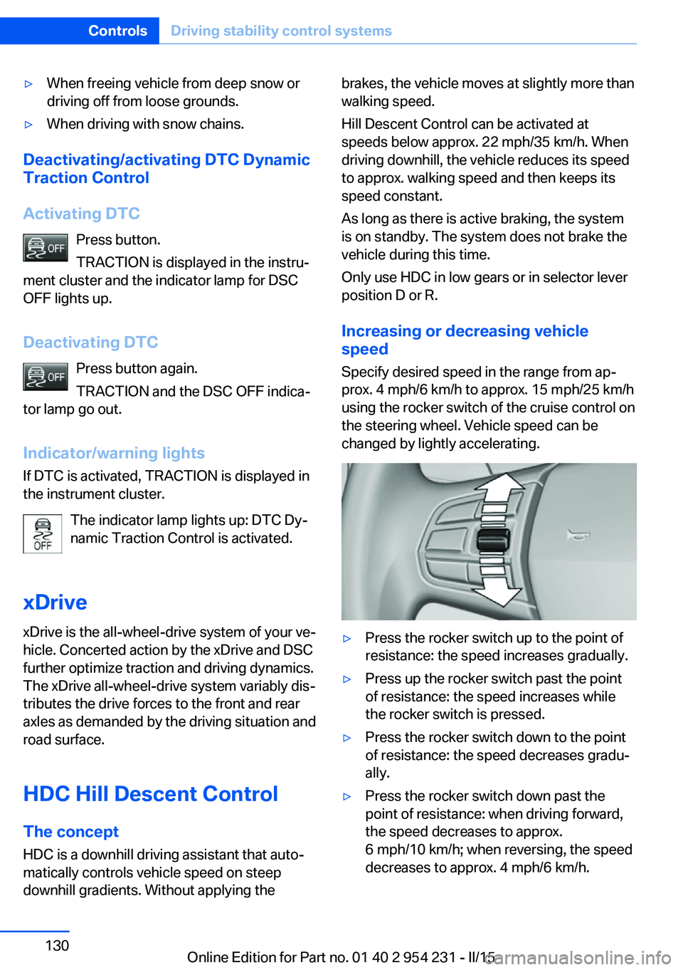
Specify desired speed in the range from ap‐
prox. 4 mph/6 km/h to approx. 15 mph/25 km/h
using the rocker switch of the cruise control on
the steering wheel. Vehicle speed can be
changed by lightly accelerating.▷Press the rocker switch up to the point of
resistance: the speed increases gradually.▷Press up the rocker switch past the point
of resistance: the speed increases while
the rocker switch is pressed.▷Press the rocker switch down to the point
of resistance: the speed decreases gradu‐
ally.▷Press the rocker switch down past the
point of resistance: when driving forward,
the speed decreases to approx.
6 mph/10 km/h; when reversing, the speed
decreases to approx. 4 mph/6 km/h.Seite 130ControlsDriving stability control systems130
Online Edition for Part no. 01 40 2 954 231 - II/15
Page 135 of 255
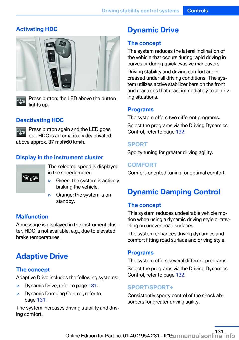
Activating HDC
Press button; the LED above the button
lights up.
Deactivating HDC Press button again and the LED goes
out. HDC is automatically deactivated
above approx. 37 mph/60 km/h.
Display in the instrument cluster The selected speed is displayed
in the speedometer.
▷Green: the system is actively
braking the vehicle.▷Orange: the system is on
standby.
Malfunction
A message is displayed in the instrument clus‐
ter. HDC is not available, e.g., due to elevated
brake temperatures.
Adaptive Drive
The concept Adaptive Drive includes the following systems:
▷Dynamic Drive, refer to page 131.▷Dynamic Damping Control, refer to
page 131.
The system increases driving stability and driv‐
ing comfort.
Dynamic Drive
The concept The system reduces the lateral inclination of
the vehicle that occurs during rapid driving in curves or during quick evasive maneuvers.
Driving stability and driving comfort are in‐
creased under all driving conditions. The sys‐
tem utilizes active stabilizer bars on the front
and rear axles that react immediately to all driv‐
ing situations.
Programs The system offers two different programs.
Select the programs via the Driving Dynamics
Control, refer to page 132.
SPORT
Sporty tuning for greater driving agility.
COMFORT
Comfort-oriented tuning for optimal comfort.
Dynamic Damping Control The concept
This system reduces undesirable vehicle mo‐
tion when using a dynamic driving style or trav‐
eling on uneven road surfaces.
The system enhances driving dynamics and
comfort fitting road surface and driving style.
Programs The system offers several different programs.
Select the programs via the Driving Dynamics
Control, refer to page 132.
SPORT/SPORT+
Consistently sporty control of the shock ab‐
sorbers for greater driving agility.Seite 131Driving stability control systemsControls131
Online Edition for Part no. 01 40 2 954 231 - II/15
Page 140 of 255
Driving comfortVehicle features and options
This chapter describes all standard, country-
specific and optional features offered with the
series. It also describes features that are not
necessarily available in your car, e. g., due to
the selected options or country versions. This
also applies to safety-related functions and
systems. The respectively applicable country
provisions must be observed when using the
respective features and systems.
Active Cruise Control with Stop & Go function, ACC
The concept
Use this system to select a desired speed that
the vehicle will maintain automatically on clear
roads.
To the extent possible, the system automati‐
cally adjusts the speed to a slower vehicle
ahead of you.
The distance that the vehicle maintains to the
vehicle ahead of you can be varied.
For safety reasons, it depends on the speed.
To maintain a certain distance, the system au‐
tomatically reduces the speed, applies the
brakes lightly, or accelerates again if the vehi‐
cle ahead begins moving faster.
If the vehicle ahead of you brakes to a halt, and
then proceeds to drive again within a brief pe‐
riod, the system is able to detect this within the
given system limits. Your own vehicle will
brake automatically and then accelerate again.
If the vehicle ahead of you drives away again
after a prolonged period, briefly press the ac‐
celerator pedal or press the appropriate button
to reactivate the system. The vehicle will auto‐
matically accelerate.As soon as the road is clear, the vehicle accel‐
erates to the desired speed.
The speed is also maintained downhill, but
may not be maintained uphill if engine power is
insufficient.
General information
Depending on the driving settings, the features
of the cruise control can change in certain
areas.
Hints Personal responsibility
Even an active system holds the driver
responsible for his or her driving, particularly
for staying in your lane, adjusting your speed,
keeping your distance and for your driving
style all in relation to traffic.
Technically the system has its limits, it cannot
independently react to all traffic situations.
Monitor your driving, be on the alert, observe
the vehicle surroundings and other traffic and
react when needed, e.g. through braking,
steering or make evasive maneuvers - risk of
accident.◀
Unfavorable weather conditions
In the event of unfavorable weather and
light conditions, e. g. if there is rain, snowfall,
slush, fog or glare, this may result in poorer
recognition of vehicles as well as short-term
interruptions for vehicles that are already de‐
tected. Drive attentively, and react to the cur‐
rent traffic situation. Intervene actively when
necessary, e.g., by braking, steering or making
an evasive maneuver, otherwise, there is the
risk of an accident.◀Seite 136ControlsDriving comfort136
Online Edition for Part no. 01 40 2 954 231 - II/15
Page 142 of 255
The indicator lights in the instrument cluster
light up and the mark in the speedometer is set
to the current speed.
Cruise control can be used.
Switch off Deactivated or interrupted system
With deactivated or interrupted system
use your brakes, steering and moves as usual
to avoid the chance of an accident.◀
To switch off the system while standing, step
on brake pedal at the same time.
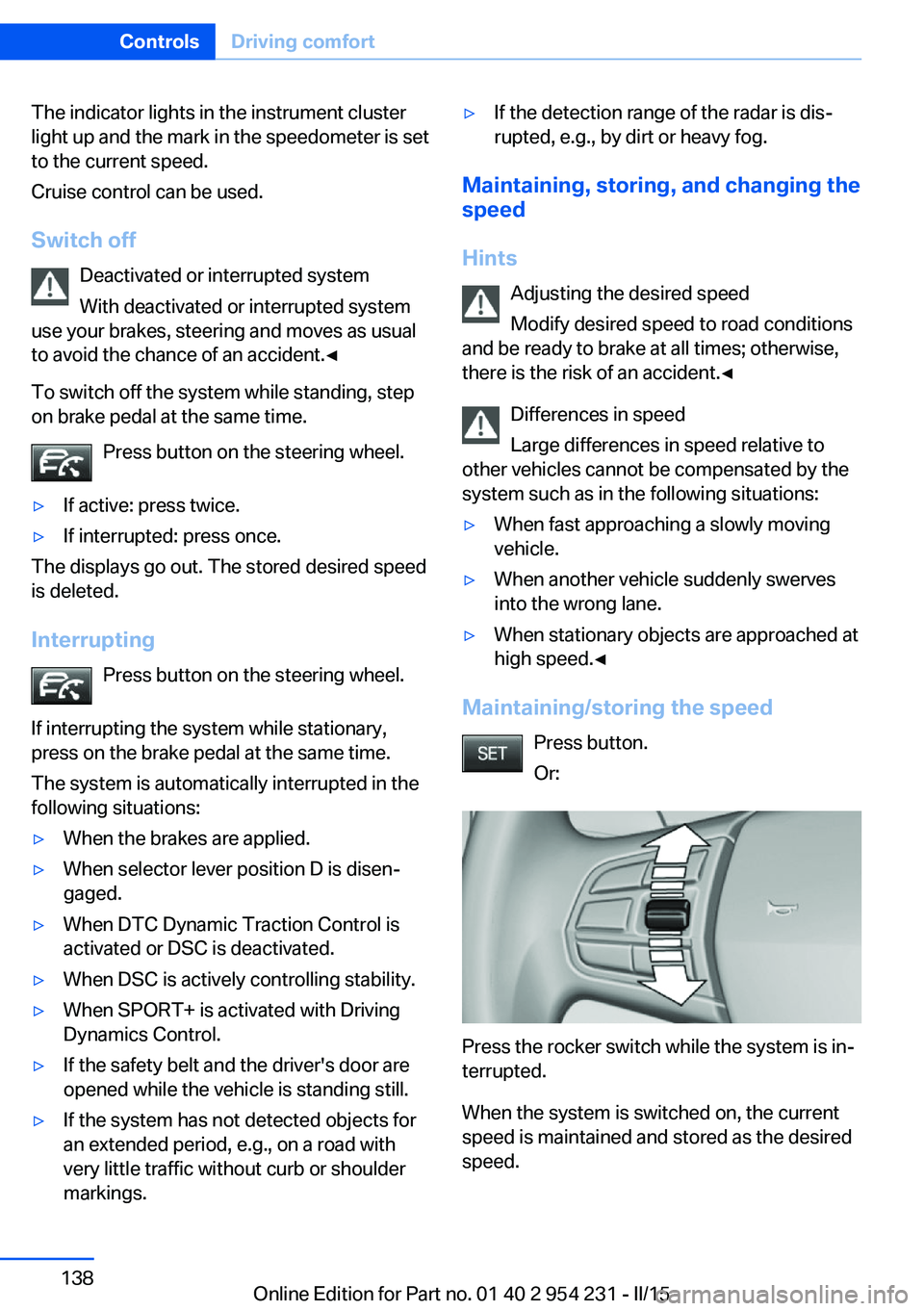
Press button on the steering wheel.▷If active: press twice.▷If interrupted: press once.
The displays go out. The stored desired speed
is deleted.
Interrupting Press button on the steering wheel.
If interrupting the system while stationary,
press on the brake pedal at the same time.
The system is automatically interrupted in the
following situations:
▷When the brakes are applied.▷When selector lever position D is disen‐
gaged.▷When DTC Dynamic Traction Control is
activated or DSC is deactivated.▷When DSC is actively controlling stability.▷When SPORT+ is activated with Driving
Dynamics Control.▷If the safety belt and the driver's door are
opened while the vehicle is standing still.▷If the system has not detected objects for
an extended period, e.g., on a road with
very little traffic without curb or shoulder
markings.▷If the detection range of the radar is dis‐
rupted, e.g., by dirt or heavy fog.
Maintaining, storing, and changing the
speed
Hints Adjusting the desired speedModify desired speed to road conditions
and be ready to brake at all times; otherwise,
there is the risk of an accident.◀
Differences in speed
Large differences in speed relative to
other vehicles cannot be compensated by the
system such as in the following situations:
▷When fast approaching a slowly moving
vehicle.▷When another vehicle suddenly swerves
into the wrong lane.▷When stationary objects are approached at
high speed.◀
Maintaining/storing the speed
Press button.
Or:
Press the rocker switch while the system is in‐
terrupted.
When the system is switched on, the current
speed is maintained and stored as the desired
speed.
Seite 138ControlsDriving comfort138
Online Edition for Part no. 01 40 2 954 231 - II/15
Page 144 of 255
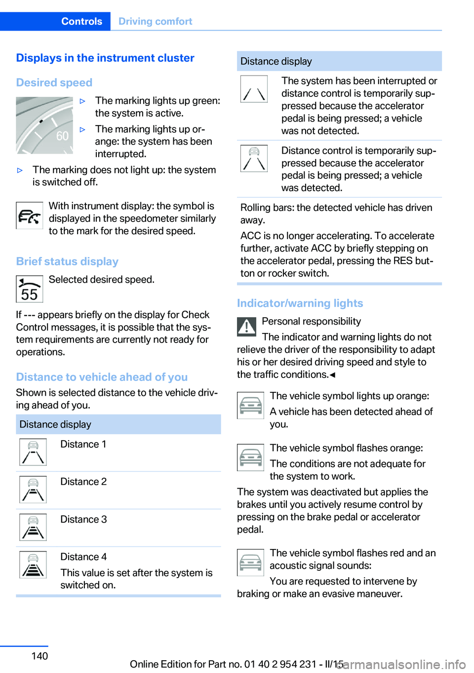
Displays in the instrument cluster
Desired speed▷The marking lights up green:
the system is active.▷The marking lights up or‐
ange: the system has been
interrupted.▷The marking does not light up: the system
is switched off.
With instrument display: the symbol is
displayed in the speedometer similarly
to the mark for the desired speed.
Brief status display Selected desired speed.
If --- appears briefly on the display for Check
Control messages, it is possible that the sys‐
tem requirements are currently not ready for
operations.
Distance to vehicle ahead of you
Shown is selected distance to the vehicle driv‐
ing ahead of you.
Distance displayDistance 1Distance 2Distance 3Distance 4
This value is set after the system is
switched on.Distance displayThe system has been interrupted or
distance control is temporarily sup‐
pressed because the accelerator
pedal is being pressed; a vehicle
was not detected.Distance control is temporarily sup‐
pressed because the accelerator
pedal is being pressed; a vehicle
was detected.Rolling bars: the detected vehicle has driven
away.
ACC is no longer accelerating. To accelerate
further, activate ACC by briefly stepping on
the accelerator pedal, pressing the RES but‐
ton or rocker switch.
Indicator/warning lights
Personal responsibility
The indicator and warning lights do not
relieve the driver of the responsibility to adapt
his or her desired driving speed and style to
the traffic conditions.◀
The vehicle symbol lights up orange:
A vehicle has been detected ahead of
you.
The vehicle symbol flashes orange:
The conditions are not adequate for
the system to work.
The system was deactivated but applies the
brakes until you actively resume control by
pressing on the brake pedal or accelerator
pedal.
The vehicle symbol flashes red and an
acoustic signal sounds:
You are requested to intervene by
braking or make an evasive maneuver.
Seite 140ControlsDriving comfort140
Online Edition for Part no. 01 40 2 954 231 - II/15
Page 148 of 255
Maintaining, storing, and changing the
speed
Hints Adjusting the desired speed
Modify desired speed to road conditions
and be ready to brake at all times; otherwise,
there is the risk of an accident.◀
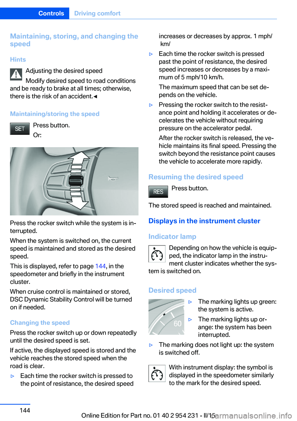
Maintaining/storing the speed Press button.
Or:
Press the rocker switch while the system is in‐
terrupted.
When the system is switched on, the current
speed is maintained and stored as the desired
speed.
This is displayed, refer to page 144, in the
speedometer and briefly in the instrument
cluster.
When cruise control is maintained or stored,
DSC Dynamic Stability Control will be turned
on if needed.
Changing the speed
Press the rocker switch up or down repeatedly
until the desired speed is set.
If active, the displayed speed is stored and the
vehicle reaches the stored speed when the
road is clear.
▷Each time the rocker switch is pressed to
the point of resistance, the desired speedincreases or decreases by approx. 1 mph/
km/▷Each time the rocker switch is pressed
past the point of resistance, the desired
speed increases or decreases by a maxi‐
mum of 5 mph/10 km/h.
The maximum speed that can be set de‐
pends on the vehicle.▷Pressing the rocker switch to the resist‐
ance point and holding it accelerates or de‐
celerates the vehicle without requiring
pressure on the accelerator pedal.
After the rocker switch is released, the ve‐
hicle maintains its final speed. Pressing the
switch beyond the resistance point causes
the vehicle to accelerate more rapidly.
Resuming the desired speed
Press button.
The stored speed is reached and maintained. Displays in the instrument cluster
Indicator lamp Depending on how the vehicle is equip‐
ped, the indicator lamp in the instru‐
ment cluster indicates whether the sys‐
tem is switched on.
Desired speed
▷The marking lights up green:
the system is active.▷The marking lights up or‐
ange: the system has been
interrupted.▷The marking does not light up: the system
is switched off.
With instrument display: the symbol is
displayed in the speedometer similarly
to the mark for the desired speed.
Seite 144ControlsDriving comfort144
Online Edition for Part no. 01 40 2 954 231 - II/15
Page 158 of 255
▷Maximum distance to row of parked vehi‐
cles: 5 ft/1.5 m.
Suitable parking space
▷Gap between two objects with a minimum
length of approx. 5 ft/1.5 m.▷Min. length of gap between two objects:
your vehicle's length plus approx.
4 ft/1.2 m.▷Minimum depth: approx. 5 ft/1.5 m.
Regarding the parking procedure
▷Doors and trunk lid closed.▷Parking brake released.▷When parking in parking spaces on the
driver's side, the corresponding turn signal
must be set where applicable.
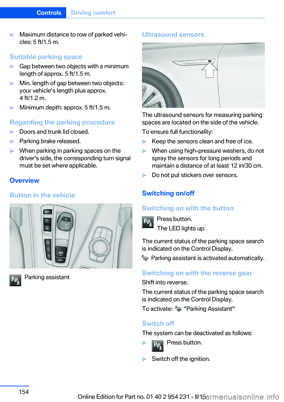
Overview
Button in the vehicle
Parking assistant
Ultrasound sensors
The ultrasound sensors for measuring parking
spaces are located on the side of the vehicle.
To ensure full functionality:
▷Keep the sensors clean and free of ice.▷When using high-pressure washers, do not
spray the sensors for long periods and
maintain a distance of at least 12 in/30 cm.▷Do not put stickers over sensors.
Switching on/off
Switching on with the button Press button.
The LED lights up.
The current status of the parking space search
is indicated on the Control Display.
Parking assistant is activated automatically.
Switching on with the reverse gear
Shift into reverse.
The current status of the parking space search
is indicated on the Control Display.
To activate:
"Parking Assistant"
Switch off
The system can be deactivated as follows:
▷Press button.▷Switch off the ignition.Seite 154ControlsDriving comfort154
Online Edition for Part no. 01 40 2 954 231 - II/15
Page 184 of 255
Objects within the range of movement
of the pedals
No objects in the area around the pedals
Keep floor mats, carpets, and any other
objects out of the pedal area; otherwise, the
function of the pedals could be impeded while
driving and create the risk of an accident.
Do not place additional floor mats over existing
mats or other objects.
Only use floor mats that have been approved
for the vehicle and can be properly attached to
floor.
Ensure that the floor mats are securely fas‐
tened again after they were removed for clean‐
ing, e.g.◀
Driving in wet conditions When roads are wet, salted, or in heavy rain,
press brake pedal ever so gently every few
miles.
Ensure that this action does not endanger other traffic.
The heat generated in this process helps dry
the brake discs and pads.
In this way braking efficiency will be available
when you need it.
Hills Avoid stressing the brakes
Avoid placing excessive stress on the
brake system. Light but consistent brake pres‐
sure can lead to high temperatures, brakes
wearing out and possibly even brake failure.◀
Do not drive in neutral
Do not drive in neutral or with the engine
stopped, as doing so disables engine braking.
In addition, steering and brake assist are un‐
available with the engine stopped.◀
Drive long or steep downhill gradients in the
gear that requires least braking efforts. Other‐wise the brakes may overheat and reduce
brake efficiency.
You can increase the engine's braking effect
by shifting down, going all the way to first gear,
if needed.
Brake disc corrosion
Brake disc corrosion and contamination of the
brake pads are favored by:▷Low mileage.▷Extended periods when the vehicle is not
used at all.▷Infrequent use of the brakes.
Corrosion will built up when the maximum
pressure applied to the brake pads during
braking is not reached - thus discs don't get
cleaned.
Corrosion buildup on the brake discs will cause
a pulsating effect on the brakes in their re‐
sponse - generally that cannot be corrected.
Condensation under the parked
vehicle
When using the automatic climate control,
condensation water develops collecting under‐
neath the vehicle.
These traces of water under the vehicle are
normal.
Seite 180Driving tipsThings to remember when driving180
Online Edition for Part no. 01 40 2 954 231 - II/15
Page 225 of 255
LED front fog lights
These front fog lights are made using LED
technology. Contact your service center in the
event of a malfunction.
Turn signal in exterior mirror The turn signals in the exterior mirrors feature
LED technology. Contact your service center in the event of a malfunction.
Tail lights, bulb replacement
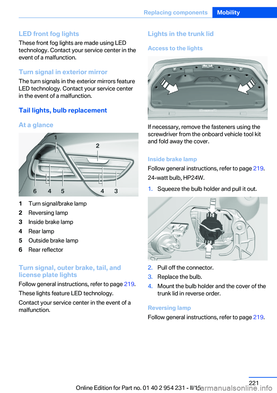
At a glance1Turn signal/brake lamp2Reversing lamp3Inside brake lamp4Rear lamp5Outside brake lamp6Rear reflector
Turn signal, outer brake, tail, and
license plate lights
Follow general instructions, refer to page 219.
These lights feature LED technology.
Contact your service center in the event of a
malfunction.
Lights in the trunk lid
Access to the lights
If necessary, remove the fasteners using the
screwdriver from the onboard vehicle tool kit
and fold away the cover.
Inside brake lamp
Follow general instructions, refer to page 219.
24-watt bulb, HP24W.
1.Squeeze the bulb holder and pull it out.2.Pull off the connector.3.Replace the bulb.4.Mount the bulb holder and the cover of the
trunk lid in reverse order.
Reversing lamp
Follow general instructions, refer to page 219.
Seite 221Replacing componentsMobility221
Online Edition for Part no. 01 40 2 954 231 - II/15