tow BMW 650I XDRIVE GRAN COUPE 2013 Owners Manual
[x] Cancel search | Manufacturer: BMW, Model Year: 2013, Model line: 650I XDRIVE GRAN COUPE, Model: BMW 650I XDRIVE GRAN COUPE 2013Pages: 232, PDF Size: 9.31 MB
Page 21 of 232
The function will run immediately. This means,
for example, that the number is dialed when a
phone number is selected.
Displaying the button assignment
Use a finger to touch the buttons. Do not wear
gloves or use objects.
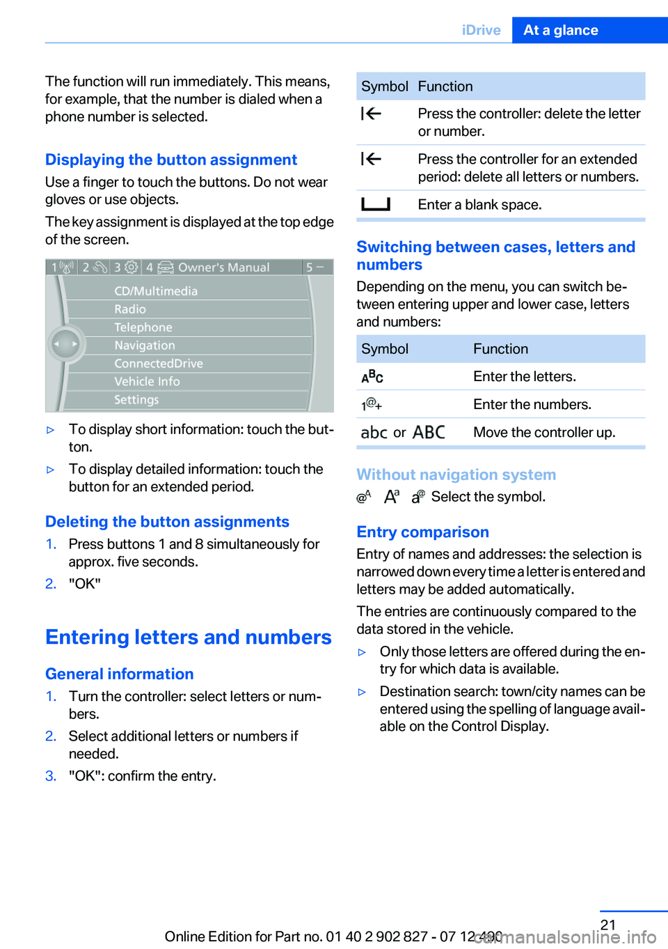
The key assignment is displayed at the top edge
of the screen.▷To display short information: touch the but‐
ton.▷To display detailed information: touch the
button for an extended period.
Deleting the button assignments
1.Press buttons 1 and 8 simultaneously for
approx. five seconds.2."OK"
Entering letters and numbers
General information
1.Turn the controller: select letters or num‐
bers.2.Select additional letters or numbers if
needed.3."OK": confirm the entry.SymbolFunction Press the controller: delete the letter
or number. Press the controller for an extended
period: delete all letters or numbers. Enter a blank space.
Switching between cases, letters and
numbers
Depending on the menu, you can switch be‐
tween entering upper and lower case, letters
and numbers:
SymbolFunction Enter the letters. Enter the numbers. or Move the controller up.
Without navigation system
Select the symbol.
Entry comparison
Entry of names and addresses: the selection is
narrowed down every time a letter is entered and
letters may be added automatically.
The entries are continuously compared to the
data stored in the vehicle.
▷Only those letters are offered during the en‐
try for which data is available.▷Destination search: town/city names can be
entered using the spelling of language avail‐
able on the Control Display.Seite 21iDriveAt a glance21
Online Edition for Part no. 01 40 2 902 827 - 07 12 490
Page 35 of 232
Locking from the outside
Do not lock the vehicle from the outside if
there are people in it, as the vehicle cannot be
unlocked from inside without special knowl‐
edge.◀
Switching on interior lamps and
courtesy lamps
Press the button on the remote control
with the vehicle locked.
Panic mode
You can trigger the alarm system if you find
yourself in a dangerous situation.
Press the button on the remote control
for at least 3 seconds.
To switch off the alarm: press any button.
Switching on the headlamp courtesy
delay feature
Briefly press the button on the remote
control.
The duration can be set in the Control Display.
Opening the trunk lid Press the button on the remote control
for approx. 1 second.
The trunk lid opens, regardless of whether it was
previously locked or unlocked.
During opening, the trunk lid pivots back and up.
Ensure that adequate clearance is available be‐
fore opening.
In some vehicle equipment variants, the trunk lid
can only be opened using the remote control if
the vehicle was unlocked first.
To avoid locking yourself out of the vehicle, do
not place the remote control into the cargo area.
The trunk lid is locked again as soon as it is
pushed closed.Confirmation signals from the vehicle1."Settings"2."Door locks"3.Deactivate or activate the desired confirma‐
tion signals.▷"Acoustic sig. lock/unlock"▷"Flash when lock/unlock"
Retrieving the seat, mirror, and
steering wheel settings
The driver's seat, exterior mirror, and steering
wheel positions selected last are stored for the
currently used remote control.
When the vehicle is unlocked, these positions
are automatically retrieved if this function was
activated.
Pinch hazard when moving back the seat
If this function is used, first make sure that
the footwell behind the driver's seat is empty.
Otherwise, people can be injured or objects
damaged when the seat is moved back.◀
The adjustment procedure is interrupted:
▷When a seat position switch is pressed.▷When a button of the seat, mirror, and steer‐
ing wheel memory is pressed briefly.
Activating the setting
1."Settings"2."Door locks"3."Last seat position auto."
Malfunction
If the vehicle can no longer be locked or un‐
locked with the remote control, the battery may
be discharged or there may be interference from
external sources such as mobile phones, metal
objects, overhead power lines, transmission
towers, etc.
If this occurs, unlock or lock the vehicle at the
door lock using the integrated key.
Seite 35Opening and closingControls35
Online Edition for Part no. 01 40 2 902 827 - 07 12 490
Page 40 of 232
Malfunction
Comfort Access may not function properly if it
experiences interference from external sources
such as mobile phones, metal objects, overhead
power lines, transmission towers, etc.
In this case, open or close the vehicle using the
buttons on the remote control or use the
integrated key in the door lock.
Alarm system
The concept
The vehicle alarm system responds to:▷Opening of a door, the hood or the trunk lid.▷Movements in the vehicle.▷Changes in the vehicle tilt, e.g., during at‐
tempts to steal a wheel or when towing the
car.▷Interruptions in battery voltage.
The alarm system briefly indicates tampering:
▷By sounding an acoustic alarm.▷By switching on the hazard warning system.▷By flashing the high beams.
Arming and disarming the alarm
system
General information
When you lock or unlock the vehicle, either with
the remote control, Comfort Access or at the
door lock the alarm system is armed or disarmed
at the same time.
Door lock and armed alarm system
Unlocking via the door lock will trigger the alarm
on some country-specific versions.
In order to terminate this alarm, unlock vehicle
with the remote control or switch on the ignition,
if necessary, by emergency detection of the re‐
mote control.
Trunk lid and armed alarm system
The trunk lid can be opened using the remote
control, even if the alarm system is armed.
Press the button on the remote control
for approx. 1 second.
After the trunk lid is closed, it is locked and
monitored again by the alarm system. The haz‐
ard warning system flashes once.
In some vehicle equipment variants, the trunk lid
can only be opened using the remote control if
the vehicle was unlocked first.
Panic mode Press the button on the remote control
for at least 3 seconds.
Switching off the alarm▷Unlock the vehicle using the remote control.▷With Comfort Access: if you are carrying the
remote control with you, pull on the door
handle.
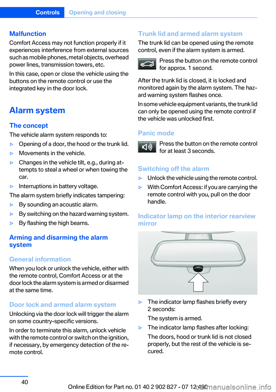
Indicator lamp on the interior rearview
mirror
▷The indicator lamp flashes briefly every
2 seconds:
The system is armed.▷The indicator lamp flashes after locking:
The doors, hood or trunk lid is not closed
properly, but the rest of the vehicle is se‐
cured.Seite 40ControlsOpening and closing40
Online Edition for Part no. 01 40 2 902 827 - 07 12 490
Page 41 of 232
After 10 seconds, the indicator lamp flashes
continuously. Interior motion sensor and tilt
alarm sensor are not active.▷The indicator lamp goes out after unlocking:
The vehicle has not been tampered with.▷The indicator lamp flashes after unlocking
until the engine is started, but no longer than
approx. 5 minutes:
An alarm has been triggered.
Tilt alarm sensor
The tilt of the vehicle is monitored.
The alarm system responds in situations such
as attempts to steal a wheel or when the car is
towed.
Interior motion sensor
The windows and glass sunroof must be closed
for the system to function properly.
Avoiding unintentional alarms
The tilt alarm sensor and interior motion sensor
can be switched off together, such as in the fol‐
lowing situations:
▷In automatic car washes.▷In duplex garages.▷During transport on car-carrying trains, at
sea or on a trailer.▷When animals are to remain in the vehicle.
Switching off the tilt alarm sensor and
interior motion sensor
Press the remote control button again
within 10 seconds as soon as the vehicle
is locked.
The indicator lamp lights up for approx. 2 sec‐
onds and then continues to flash.
The tilt alarm sensor and interior motion sensor
are switched off until the vehicle is locked again.
Power windows
General information Take the remote control with you
Take the remote control with you when
leaving the vehicle so that children, for example,
cannot operate the power windows and injure
themselves.◀
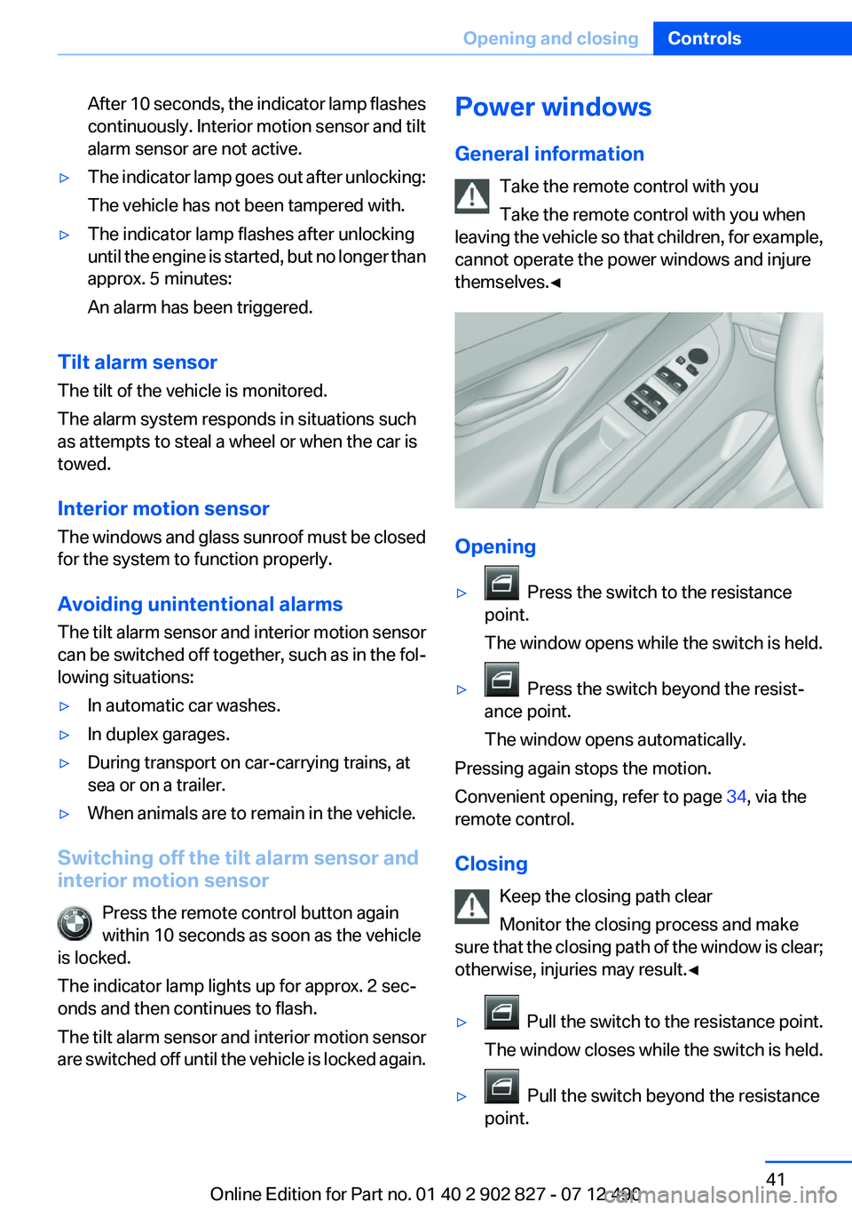
Opening
▷ Press the switch to the resistance
point.
The window opens while the switch is held.▷ Press the switch beyond the resist‐
ance point.
The window opens automatically.
Pressing again stops the motion.
Convenient opening, refer to page 34, via the
remote control.
Closing Keep the closing path clear
Monitor the closing process and make
sure that the closing path of the window is clear;
otherwise, injuries may result.◀
▷ Pull the switch to the resistance point.
The window closes while the switch is held.▷ Pull the switch beyond the resistance
point.
Seite 41Opening and closingControls41
Online Edition for Part no. 01 40 2 902 827 - 07 12 490
Page 43 of 232
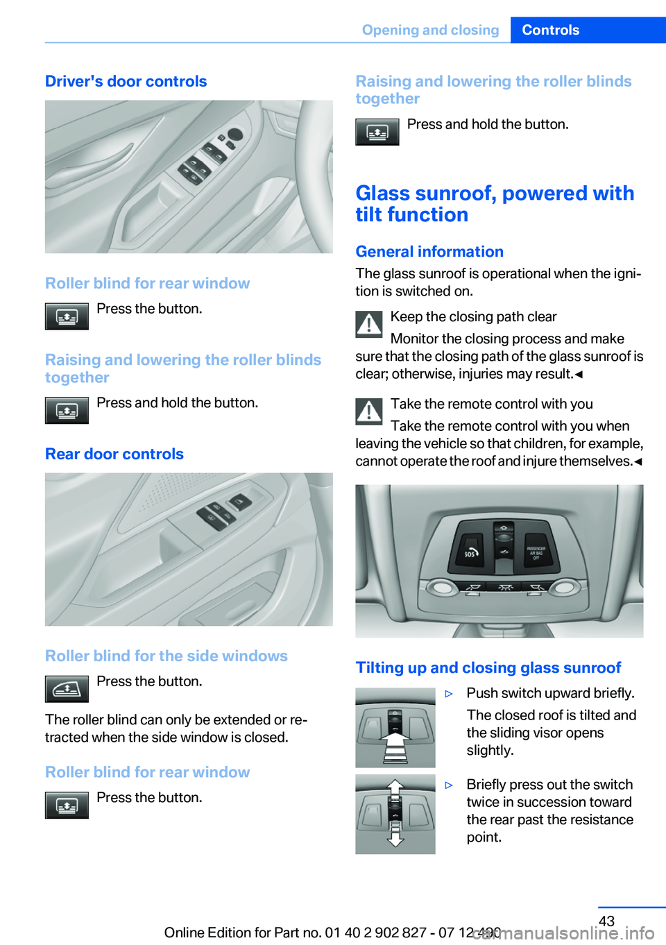
Driver's door controls
Roller blind for rear windowPress the button.
Raising and lowering the roller blinds
together
Press and hold the button.
Rear door controls
Roller blind for the side windows Press the button.
The roller blind can only be extended or re‐
tracted when the side window is closed.
Roller blind for rear window Press the button.
Raising and lowering the roller blinds
together
Press and hold the button.
Glass sunroof, powered with
tilt function
General information
The glass sunroof is operational when the igni‐
tion is switched on.
Keep the closing path clear
Monitor the closing process and make
sure that the closing path of the glass sunroof is
clear; otherwise, injuries may result.◀
Take the remote control with you
Take the remote control with you when
leaving the vehicle so that children, for example,
cannot operate the roof and injure themselves. ◀
Tilting up and closing glass sunroof
▷Push switch upward briefly.
The closed roof is tilted and
the sliding visor opens
slightly.▷Briefly press out the switch
twice in succession toward
the rear past the resistance
point.Seite 43Opening and closingControls43
Online Edition for Part no. 01 40 2 902 827 - 07 12 490
Page 50 of 232
Head restraints
Correctly adjusted head restraint
A correctly adjusted head restraint reduces the
risk of injury to cervical vertebrae in the event of
an accident.
Adjusting the head restraint
If possible, correctly adjust the head re‐
straints of all occupied seats; otherwise, there is
an increased risk of injury in an accident.◀
Front
Height
Adjust the head restraint so that its center is ap‐
proximately at ear level.
Distance
Adjust the distance so that the head restraint is
as close as possible to the back of the head.
Active head restraint
In the event of a rear-end collision with a certain
severity, the active head restraint automatically
reduces the distance from the head.
Reduced protective function▷Do not use seat or head restraint cov‐
ers.▷Do not hang objects, e.g., clothes hangers,
on the head restraints.▷Only attach accessories approved by BMW
to the seat or head restraint.
Otherwise, the protective function of the active
head restraint will be impaired and the personal
safety of the occupants will be endangered.◀
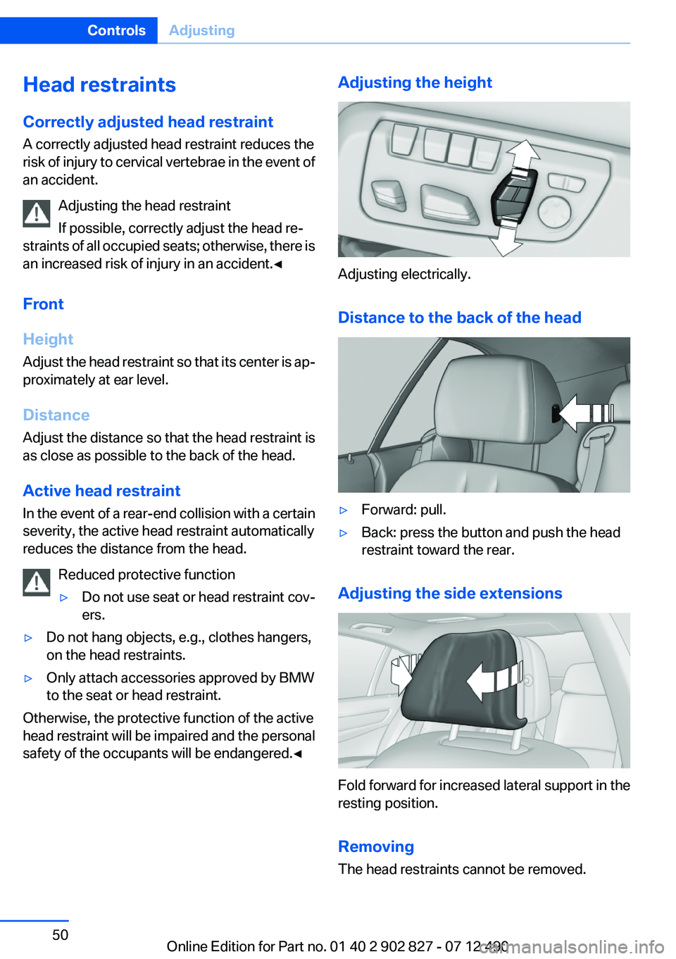
Adjusting the height
Adjusting electrically.
Distance to the back of the head
▷Forward: pull.▷Back: press the button and push the head
restraint toward the rear.
Adjusting the side extensions
Fold forward for increased lateral support in the
resting position.
Removing
The head restraints cannot be removed.
Seite 50ControlsAdjusting50
Online Edition for Part no. 01 40 2 902 827 - 07 12 490
Page 80 of 232
NotesPersonal judgment
The system cannot serve as a substitute
for the driver's personal judgment of the traffic
situation.
The system assists the driver and does not re‐
place the human eye.◀
At a glance
Camera
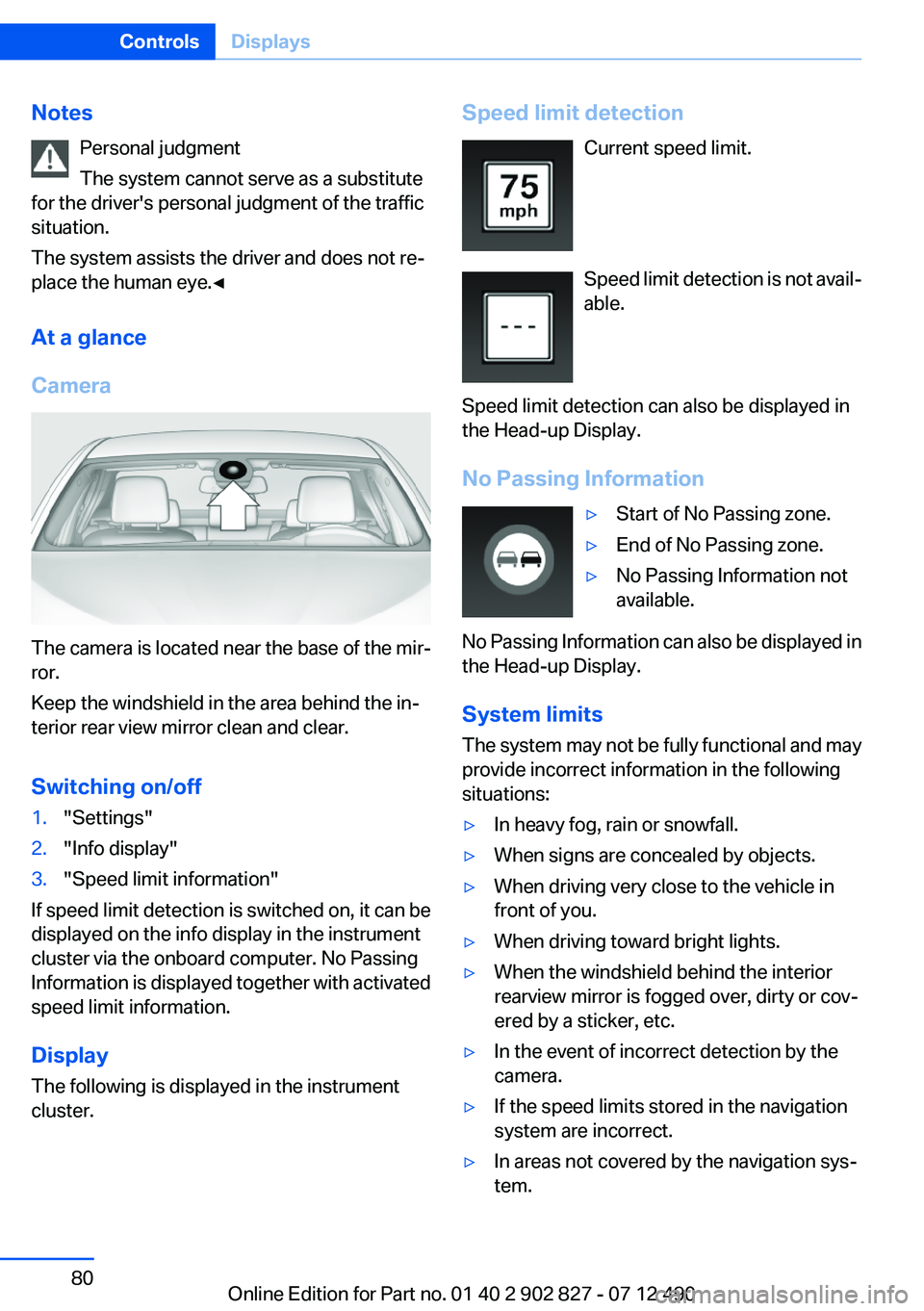
The camera is located near the base of the mir‐
ror.
Keep the windshield in the area behind the in‐
terior rear view mirror clean and clear.
Switching on/off
1."Settings"2."Info display"3."Speed limit information"
If speed limit detection is switched on, it can be
displayed on the info display in the instrument
cluster via the onboard computer. No Passing
Information is displayed together with activated
speed limit information.
Display
The following is displayed in the instrument
cluster.
Speed limit detection
Current speed limit.
Speed limit detection is not avail‐
able.
Speed limit detection can also be displayed in
the Head-up Display.
No Passing Information▷Start of No Passing zone.▷End of No Passing zone.▷No Passing Information not
available.
No Passing Information can also be displayed in
the Head-up Display.
System limits
The system may not be fully functional and may
provide incorrect information in the following
situations:
▷In heavy fog, rain or snowfall.▷When signs are concealed by objects.▷When driving very close to the vehicle in
front of you.▷When driving toward bright lights.▷When the windshield behind the interior
rearview mirror is fogged over, dirty or cov‐
ered by a sticker, etc.▷In the event of incorrect detection by the
camera.▷If the speed limits stored in the navigation
system are incorrect.▷In areas not covered by the navigation sys‐
tem.Seite 80ControlsDisplays80
Online Edition for Part no. 01 40 2 902 827 - 07 12 490
Page 88 of 232
Adaptive light control
The concept
Adaptive light control is a variable headlamp
control system that enables dynamic illumina‐
tion of the road surface.
Depending on the steering angle and other pa‐
rameters, the light from the headlamp follows
the course of the road.
In tight curves, e.g., on mountainous roads or
when turning, an additional, corner-illuminating
lamp is switched on that lights up the inside of
the curve when the vehicle is moving below a
certain speed.
Activating
Switch position
with the ignition switched
on.
The turning lamps are automatically switched
on depending on the steering angle or the use
of turn signals.
To avoid blinding oncoming traffic, the Adaptive
Light Control does not swivel to the driver's side
when the vehicle is at a standstill.
When driving in reverse, only the turning lamp is
active.
Self-leveling headlights
The self-leveling headlights feature adapts the
light distribution to the contours of the road.
The light distribution is lowered on hilltops to
avoid blinding oncoming traffic and tilted in de‐
pressions to increase visibility.
Malfunction
A Check Control message is displayed.
Adaptive light control is malfunctioning or has
failed. Have the system checked as soon as pos‐
sible.
High-beam Assistant
The concept
When the low beams are switched on, this sys‐
tem automatically switches the high beams on
and off. The procedure is controlled by a sensor
on the front of the interior rearview mirror. The
assistant ensures that the high beams are
switched on whenever the traffic situation al‐
lows. The driver can intervene at any time and
switch the high beams on and off as usual.
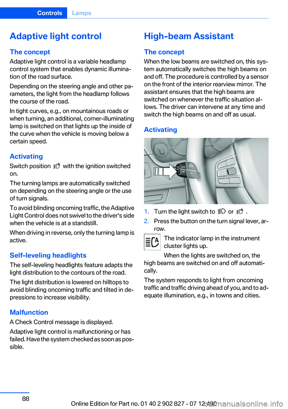
Activating1.Turn the light switch to or .2.Press the button on the turn signal lever, ar‐
row.
The indicator lamp in the instrument
cluster lights up.
When the lights are switched on, the
high beams are switched on and off automati‐
cally.
The system responds to light from oncoming
traffic and traffic driving ahead of you, and to ad‐
equate illumination, e.g., in towns and cities.
Seite 88ControlsLamps88
Online Edition for Part no. 01 40 2 902 827 - 07 12 490
Page 89 of 232
Switching the high beams on and off
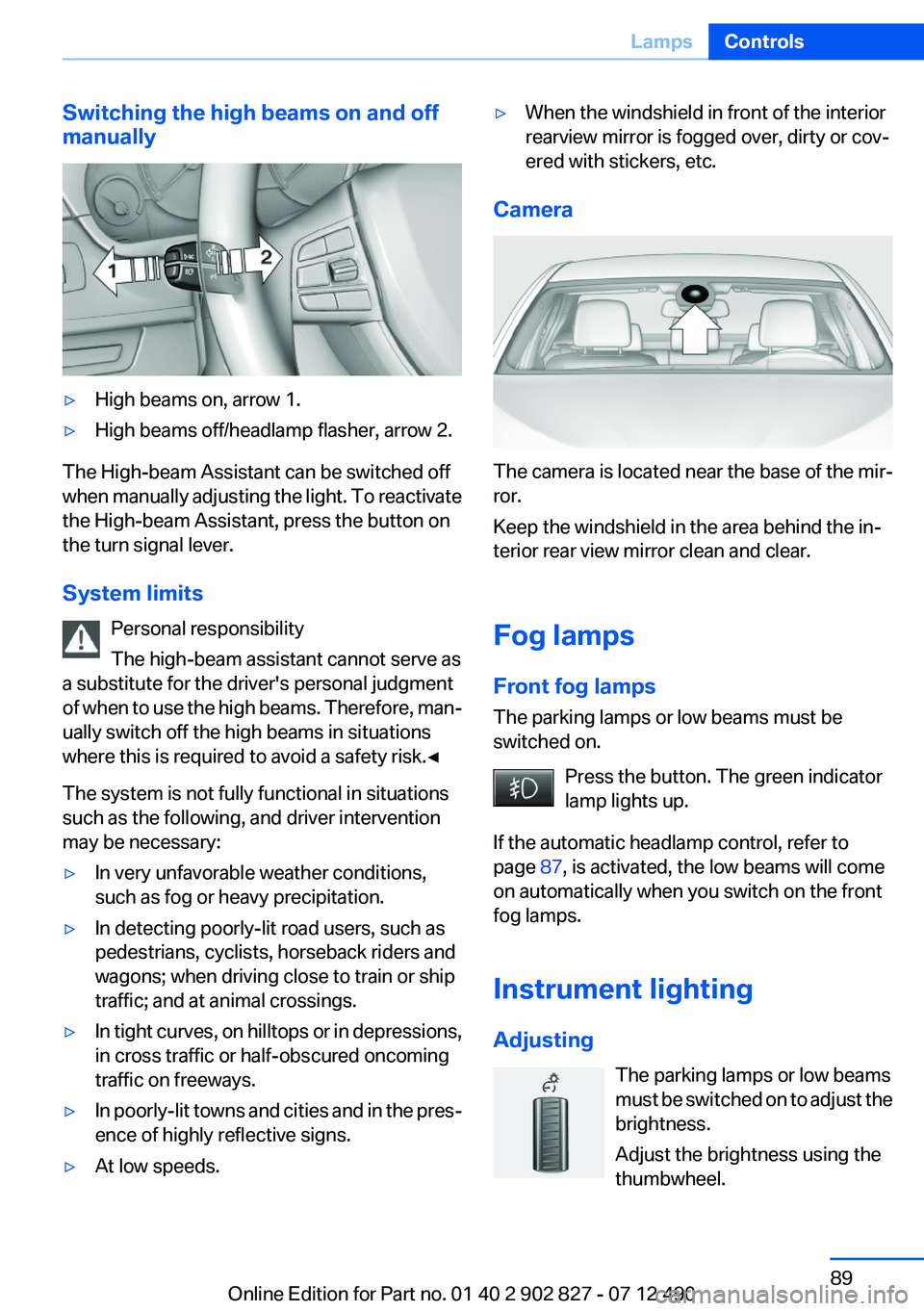
manually▷High beams on, arrow 1.▷High beams off/headlamp flasher, arrow 2.
The High-beam Assistant can be switched off
when manually adjusting the light. To reactivate
the High-beam Assistant, press the button on
the turn signal lever.
System limits Personal responsibility
The high-beam assistant cannot serve as
a substitute for the driver's personal judgment
of when to use the high beams. Therefore, man‐
ually switch off the high beams in situations
where this is required to avoid a safety risk.◀
The system is not fully functional in situations
such as the following, and driver intervention
may be necessary:
▷In very unfavorable weather conditions,
such as fog or heavy precipitation.▷In detecting poorly-lit road users, such as
pedestrians, cyclists, horseback riders and
wagons; when driving close to train or ship
traffic; and at animal crossings.▷In tight curves, on hilltops or in depressions,
in cross traffic or half-obscured oncoming
traffic on freeways.▷In poorly-lit towns and cities and in the pres‐
ence of highly reflective signs.▷At low speeds.▷When the windshield in front of the interior
rearview mirror is fogged over, dirty or cov‐
ered with stickers, etc.
Camera
The camera is located near the base of the mir‐
ror.
Keep the windshield in the area behind the in‐
terior rear view mirror clean and clear.
Fog lamps
Front fog lamps
The parking lamps or low beams must be
switched on.
Press the button. The green indicator
lamp lights up.
If the automatic headlamp control, refer to
page 87, is activated, the low beams will come
on automatically when you switch on the front
fog lamps.
Instrument lighting
Adjusting The parking lamps or low beams
must be switched on to adjust the
brightness.
Adjust the brightness using the
thumbwheel.
Seite 89LampsControls89
Online Edition for Part no. 01 40 2 902 827 - 07 12 490
Page 101 of 232
System limitsBe alert
Due to system limitations, warnings may
be not be issued at all, or may be issued late or
improperly. Therefore, always be alert and ready
to intervene; otherwise, there is the danger of an
accident occurring.◀
Detection range
The detection capacity of the camera and the
collision warning has limitations.
This may result in the warning not being issued
or being issued late.
For example, the following situations may not be
detected:▷Slow moving vehicles when you approach
them at high speed.▷Vehicles that suddenly swerve in front of you
or sharply decelerating vehicles.▷Vehicles with an unusual rear appearance.▷Two-wheeled vehicles ahead of you.
Functional limitations
The system may not be fully functional in the
following situations:
▷In heavy fog, rain, sprayed water or snowfall.▷In tight curves.▷If the camera view field or the front wind‐
shield are dirty or covered.▷When driving toward bright lights.▷In the case of vehicles with insufficiently visi‐
ble tail lamps.▷In the case of partially covered vehicles.▷Up to 10 seconds after the start of the en‐
gine, via the Start/Stop knob.▷During the calibration process of the camera
immediately after vehicle shipment.
Prewarning sensitivity
Depending on the set prewarning time, this may
result in increased false warnings.
Camera
The camera is located near the base of the mir‐
ror.
Keep the windshield in the area behind the in‐
terior rear view mirror clean and clear.
Collision warning with
braking function
The concept
If the vehicle is equipped with Active Cruise
Control with Stop & Go, the collision warning is
controlled via the cruise control radar sensor.
The system issues a two-phase warning of a
danger of collision at speeds above approx.
10 mph/15 km/h. The time of these warnings
may vary depending on the current driving sit‐
uation.
The collision warning is available even if cruise
control has been deactivated.
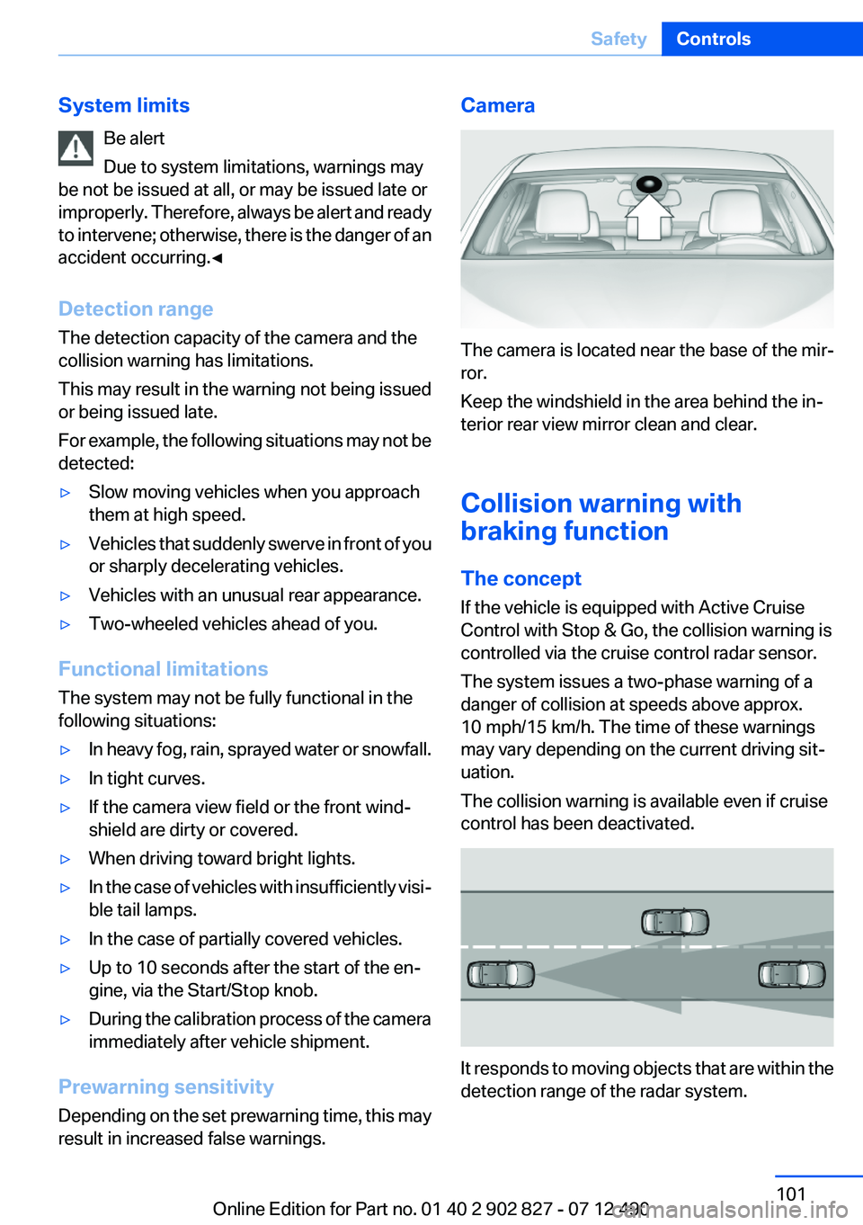
It responds to moving objects that are within the
detection range of the radar system.
Seite 101SafetyControls101
Online Edition for Part no. 01 40 2 902 827 - 07 12 490