navigation system BMW 7 SERIES 2013 F01 User Guide
[x] Cancel search | Manufacturer: BMW, Model Year: 2013, Model line: 7 SERIES, Model: BMW 7 SERIES 2013 F01Pages: 255, PDF Size: 5.22 MB
Page 95 of 255
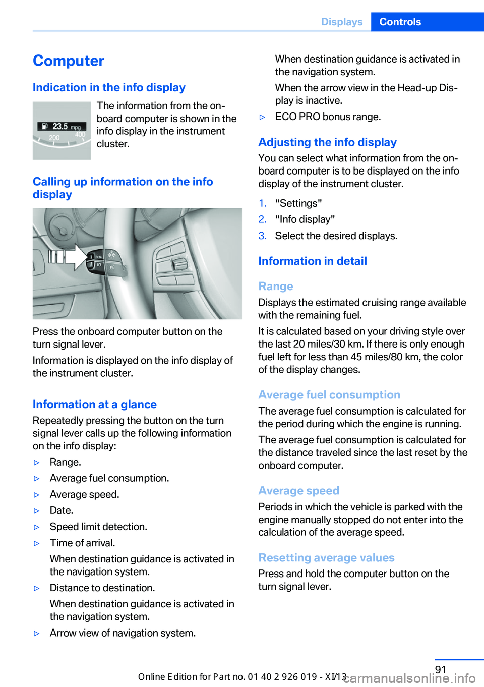
ComputerIndication in the info display The information from the on‐
board computer is shown in the
info display in the instrument
cluster.
Calling up information on the info
display
Press the onboard computer button on the
turn signal lever.
Information is displayed on the info display of
the instrument cluster.
Information at a glance
Repeatedly pressing the button on the turn
signal lever calls up the following information
on the info display:
▷Range.▷Average fuel consumption.▷Average speed.▷Date.▷Speed limit detection.▷Time of arrival.
When destination guidance is activated in
the navigation system.▷Distance to destination.
When destination guidance is activated in
the navigation system.▷Arrow view of navigation system.When destination guidance is activated in
the navigation system.
When the arrow view in the Head-up Dis‐
play is inactive.▷ECO PRO bonus range.
Adjusting the info display
You can select what information from the on‐
board computer is to be displayed on the info
display of the instrument cluster.
1."Settings"2."Info display"3.Select the desired displays.
Information in detail
Range
Displays the estimated cruising range available
with the remaining fuel.
It is calculated based on your driving style over
the last 20 miles/30 km. If there is only enough
fuel left for less than 45 miles/80 km, the color
of the display changes.
Average fuel consumption
The average fuel consumption is calculated for
the period during which the engine is running.
The average fuel consumption is calculated for
the distance traveled since the last reset by the
onboard computer.
Average speed
Periods in which the vehicle is parked with the
engine manually stopped do not enter into the
calculation of the average speed.
Resetting average values
Press and hold the computer button on the
turn signal lever.
Seite 91DisplaysControls91
Online Edition for Part no. 01 40 2 909 749 - VI/13
Page 96 of 255
Distance to destination
The distance remaining to the destination is
displayed if a destination is entered in the navi‐
gation system before the trip is started.
The distance to the destination is adopted au‐
tomatically.
Time of arrival The estimated time of arrival is
displayed if a destination is en‐
tered in the navigation system
before the trip is started.
The time must be correctly set.
Speed limit detection
Description of the speed limit detection, refer
to page 89, function.
Speed limit
Display of a speed limit which, when reached,
should cause a warning to be issued.
The warning is repeated if the vehicle speed
drops below the set speed limit once by at least 3 mph/5 km/h.
Displaying, setting or changing the
limit1."Settings"2."Speed"3."Warning at:"4.Turn the controller until the desired limit is
displayed.5.Press the controller.
The speed limit is stored.
Activating/deactivating the limit
1."Settings"2."Speed"3."Warning"4.Press the controller.Setting your current speed as the limit1."Settings"2."Speed"3."Select current speed"4.Press the controller.
The current vehicle speed is stored as the
limit.
Trip computer
The vehicle features two types of computer.
▷"Onboard info": the values can be reset as
often as necessary.▷"Trip computer": the values provide an
overview of the current trip.
Resetting the trip computer
1."Vehicle Info"2."Trip computer"3."Reset": all values are reset.
"Automatically reset": all values are reset
approx. 4 hours after the vehicle comes to
a standstill.
Display on the Control Display
Display the onboard computer or trip computer
on the Control Display.
1."Vehicle Info"2."Onboard info" or "Trip computer"
Resetting the fuel consumption or
speed
1."Vehicle Info"2."Onboard info"3."Consumpt." or "Speed"4."Yes"Seite 92ControlsDisplays92
Online Edition for Part no. 01 40 2 909 749 - VI/13
Page 144 of 255
General information
The congestion assistant determines speed
and distance from the vehicle in front via a ra‐
dar sensor and the position of the lane marking
via a camera.
Sensors on the steering wheel detect whether
the steering wheel is being touched.
The system is deactivated as soon as contact
with the steering wheel is no longer detected.
In order to be able to use the Congestion As‐
sistant, place your hands around the steering
wheel.
When driving with gloves or with protective
covers, contact with the steering wheel cannot
be detected by the sensors. The system in this
case cannot be used.
Notes Personal responsibility
The system does not relieve the driver of
the responsibility to adapt his or her speed,
distance and driving style to the traffic condi‐
tions. Drive attentively, and react to the current
traffic events. Intervene actively when neces‐
sary, e.g., by braking, steering or making an
evasive maneuver, otherwise, there is danger
of an accident.◀
Functional requirements▷Drive on approved road type. The data on
this are stored in the navigation system.▷Driving on the limited access highway or
divided lane roads.▷Sufficient lane width.▷Lane marking is detected.▷Vehicle driving ahead is detected.▷Speed below 25 mph/40 km/h.▷Both hands on the steering wheel rim.At a glance
Buttons on the steering wheelPress the
buttonFunctionCongestion Assistant ON/OFF,
Pause, refer to page 141.Rocker switch:
Store, change/maintain speed,
refer to page 135.Maintain, store speed, refer to
page 135.Resume speed, refer to
page 136.Adjust distance, refer to
page 136.
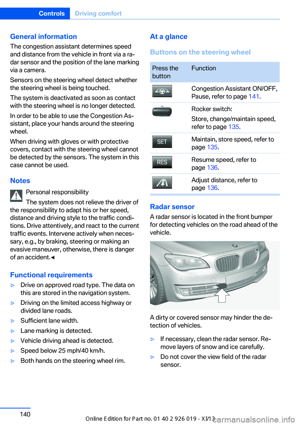
Radar sensor
A radar sensor is located in the front bumper
for detecting vehicles on the road ahead of the
vehicle.
A dirty or covered sensor may hinder the de‐
tection of vehicles.
▷If necessary, clean the radar sensor. Re‐
move layers of snow and ice carefully.▷Do not cover the view field of the radar
sensor.Seite 140ControlsDriving comfort140
Online Edition for Part no. 01 40 2 909 749 - VI/13
Page 150 of 255
Display
Signal tones When approaching an object, an intermittent
tone is sounded that indicates the position of
the object. For example, if an object is de‐
tected to the left rear of the vehicle, a signal
tone sounds from the left rear speaker.
The shorter the distance to the object be‐
comes, the shorter the intervals.
If the distance to a detected object is less than
approx. 10 in/25 cm, a continuous tone is
sounded.
If objects are located both in front of and be‐
hind the vehicle, an alternating continuous sig‐
nal is sounded.
The intermittent tone is interrupted after ap‐
prox. 3 seconds:▷If the vehicle stops in front of an object that
is detected by only one of the corner sen‐
sors.▷If moving parallel to a wall.
The signal tone is switched off:
▷When the vehicle moves away from an ob‐
ject by more than approx. 4 in/10 cm.▷When transmission position P is engaged.
Volume
The volume of the PDC signal can be adjusted,
refer to user's manual for Navigation, Enter‐
tainment, Communication.
The setting is stored for the remote control
currently in use.
Visual warning
The approach of the vehicle to an object can
be shown on the Control Display. Objects that
are farther away are displayed on the Control
Display before a signal tone sounds.
A display appears as soon as Park Distance
Control (PDC) is activated.
The range of the sensors is represented in the
colors red, green and yellow.
If the rearview camera image was selected last,
it again appears on the display. To switch to
PDC:1. "Rear view camera" Select the symbol
on the Control Display.2.Press the controller.
The setting is stored for the remote control
currently in use.
System limits
Limits of ultrasonic measurement
The detection of objects can reach the physi‐
cal limits of ultrasonic measurement, e.g.:
▷With tow bars and trailer hitches.▷With thin or wedge-shaped objects.▷With low objects.▷With objects with corners and sharp edges.
Low objects already displayed, e.g., curbs, can
move into the blind area of the sensors before
or after a continuous tone sounds.
High, protruding objects such as ledges may
not be detected.
False warnings
PDC may issue a warning under the following
conditions even though there is no obstacle
within the detection range:
▷In heavy rain.▷When sensors are very dirty or covered in
ice.▷When sensors are covered in snow.▷On rough road surfaces.▷In large buildings with right angles and
smooth walls, e.g., in underground ga‐
rages.▷In heavy exhaust.Seite 146ControlsDriving comfort146
Online Edition for Part no. 01 40 2 909 749 - VI/13
Page 158 of 255
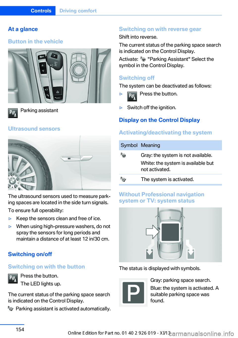
At a glance
Button in the vehicle
Parking assistant
Ultrasound sensors
The ultrasound sensors used to measure park‐
ing spaces are located in the side turn signals.
To ensure full operability:
▷Keep the sensors clean and free of ice.▷When using high-pressure washers, do not
spray the sensors for long periods and
maintain a distance of at least 12 in/30 cm.
Switching on/off
Switching on with the button Press the button.
The LED lights up.
The current status of the parking space search
is indicated on the Control Display.
Parking assistant is activated automatically.
Switching on with reverse gear
Shift into reverse.
The current status of the parking space search
is indicated on the Control Display.
Activate:
"Parking Assistant" Select the
symbol in the Control Display.
Switching off The system can be deactivated as follows:
▷Press the button.▷Switch off the ignition.
Display on the Control Display
Activating/deactivating the system
SymbolMeaning Gray: the system is not available.
White: the system is available but
not activated. The system is activated.
Without Professional navigation
system or TV: system status
The status is displayed with symbols.
Gray: parking space search.
Blue: the system is activated. A
suitable parking space was
found.
Seite 154ControlsDriving comfort154
Online Edition for Part no. 01 40 2 909 749 - VI/13
Page 159 of 255
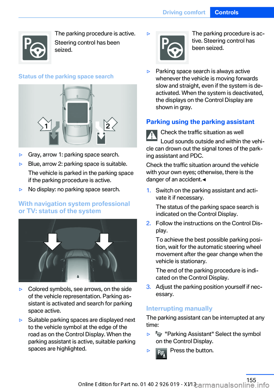
The parking procedure is active.
Steering control has been
seized.
Status of the parking space search▷Gray, arrow 1: parking space search.▷Blue, arrow 2: parking space is suitable.
The vehicle is parked in the parking space
if the parking procedure is active.▷No display: no parking space search.
With navigation system professional
or TV: status of the system
▷Colored symbols, see arrows, on the side
of the vehicle representation. Parking as‐
sistant is activated and search for parking
space active.▷Suitable parking spaces are displayed next
to the vehicle symbol at the edge of the
road as on the Control Display. When the
parking assistant is active, suitable parking
spaces are highlighted.▷The parking procedure is ac‐
tive. Steering control has
been seized.▷Parking space search is always active
whenever the vehicle is moving forwards
slow and straight, even if the system is de‐
activated. When the system is deactivated,
the displays on the Control Display are
shown in gray.
Parking using the parking assistant
Check the traffic situation as well
Loud sounds outside and within the vehi‐
cle can drown out the signal tones of the park‐
ing assistant and PDC.
Check the traffic situation around the vehicle
with your own eyes; otherwise, there is the
danger of an accident.◀
1.Switch on the parking assistant and acti‐
vate it if necessary.
The status of the parking space search is
indicated on the Control Display.2.Follow the instructions on the Control Dis‐
play.
To achieve the best possible parking posi‐
tion, wait for the automatic steering wheel
movement after the gear change when the
vehicle is stationary.
The end of the parking procedure is indi‐
cated on the Control Display.3.Adjust the parking position yourself if nec‐
essary.
Interrupting manually
The parking assistant can be interrupted at any
time:
▷ "Parking Assistant" Select the symbol
on the Control Display.▷Press the button.Seite 155Driving comfortControls155
Online Edition for Part no. 01 40 2 909 749 - VI/13
Page 161 of 255
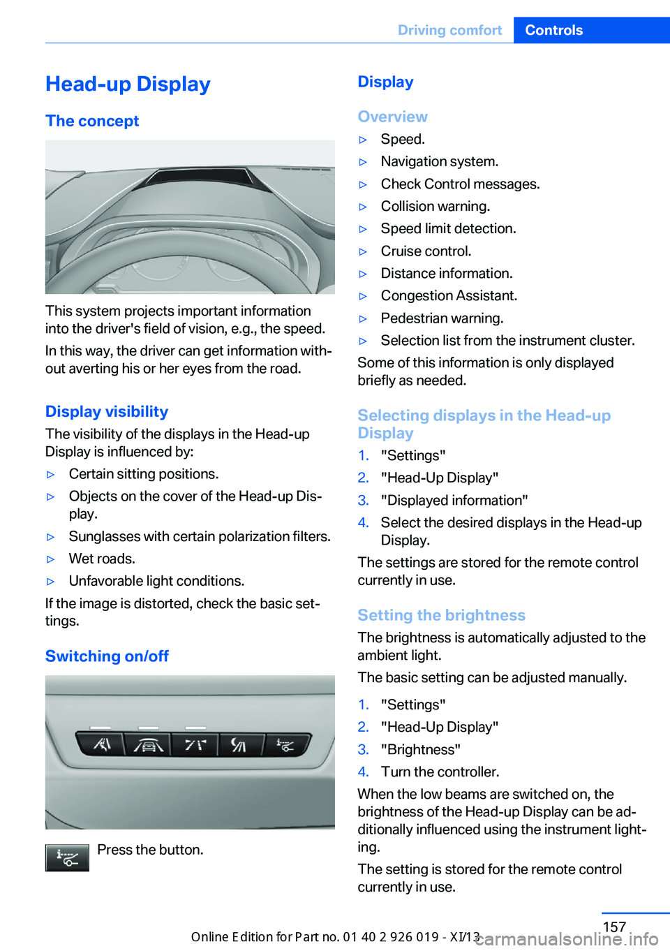
Head-up Display
The concept
This system projects important information
into the driver's field of vision, e.g., the speed.
In this way, the driver can get information with‐
out averting his or her eyes from the road.
Display visibility The visibility of the displays in the Head-up
Display is influenced by:
▷Certain sitting positions.▷Objects on the cover of the Head-up Dis‐
play.▷Sunglasses with certain polarization filters.▷Wet roads.▷Unfavorable light conditions.
If the image is distorted, check the basic set‐
tings.
Switching on/off
Press the button.
Display
Overview▷Speed.▷Navigation system.▷Check Control messages.▷Collision warning.▷Speed limit detection.▷Cruise control.▷Distance information.▷Congestion Assistant.▷Pedestrian warning.▷Selection list from the instrument cluster.
Some of this information is only displayed
briefly as needed.
Selecting displays in the Head-up
Display
1."Settings"2."Head-Up Display"3."Displayed information"4.Select the desired displays in the Head-up
Display.
The settings are stored for the remote control
currently in use.
Setting the brightness
The brightness is automatically adjusted to the
ambient light.
The basic setting can be adjusted manually.
1."Settings"2."Head-Up Display"3."Brightness"4.Turn the controller.
When the low beams are switched on, the
brightness of the Head-up Display can be ad‐
ditionally influenced using the instrument light‐
ing.
The setting is stored for the remote control
currently in use.
Seite 157Driving comfortControls157
Online Edition for Part no. 01 40 2 909 749 - VI/13
Page 176 of 255
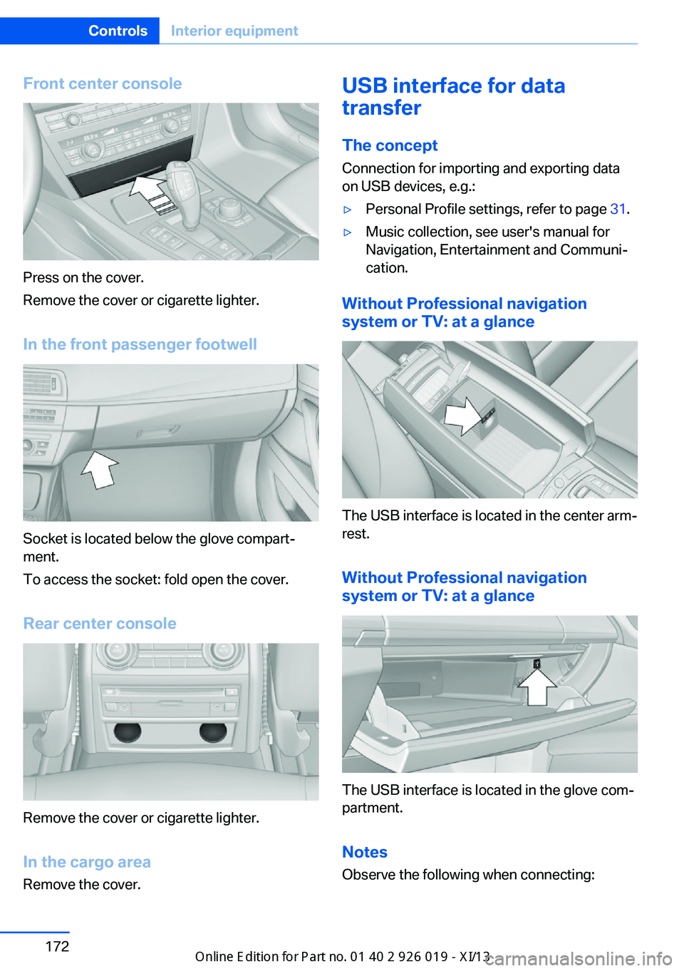
Front center console
Press on the cover.
Remove the cover or cigarette lighter.
In the front passenger footwell
Socket is located below the glove compart‐
ment.
To access the socket: fold open the cover.
Rear center console
Remove the cover or cigarette lighter.
In the cargo area Remove the cover.
USB interface for data
transfer
The concept Connection for importing and exporting data
on USB devices, e.g.:▷Personal Profile settings, refer to page 31.▷Music collection, see user's manual for
Navigation, Entertainment and Communi‐
cation.
Without Professional navigation
system or TV: at a glance
The USB interface is located in the center arm‐
rest.
Without Professional navigation
system or TV: at a glance
The USB interface is located in the glove com‐
partment.
Notes
Observe the following when connecting:
Seite 172ControlsInterior equipment172
Online Edition for Part no. 01 40 2 909 749 - VI/13
Page 227 of 255
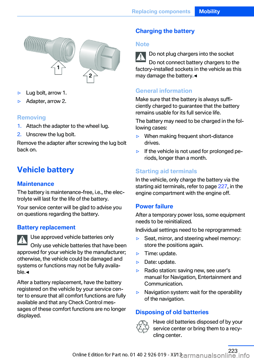
▷Lug bolt, arrow 1.▷Adapter, arrow 2.
Removing
1.Attach the adapter to the wheel lug.2.Unscrew the lug bolt.
Remove the adapter after screwing the lug bolt
back on.
Vehicle battery
Maintenance
The battery is maintenance-free, i.e., the elec‐
trolyte will last for the life of the battery.
Your service center will be glad to advise you
on questions regarding the battery.
Battery replacement Use approved vehicle batteries only
Only use vehicle batteries that have been
approved for your vehicle by the manufacturer;
otherwise, the vehicle could be damaged and
systems or functions may not be fully availa‐
ble.◀
After a battery replacement, have the battery
registered on the vehicle by your service cen‐
ter to ensure that all comfort functions are fully
available and that any Check Control mes‐
sages of these comfort functions are no longer
displayed.
Charging the battery
Note Do not plug chargers into the socketDo not connect battery chargers to the
factory-installed sockets in the vehicle as this
may damage the battery.◀
General information Make sure that the battery is always suffi‐
ciently charged to guarantee that the battery
remains usable for its full service life.
The battery may need to be charged in the fol‐
lowing cases:▷When making frequent short-distance
drives.▷If the vehicle is not used for prolonged pe‐
riods, longer than a month.
Starting aid terminals
In the vehicle, only charge the battery via the
starting aid terminals, refer to page 227, in the
engine compartment with the engine off.
Power failure After a temporary power loss, some equipment
needs to be reinitialized.
Individual settings need to be reprogrammed:
▷Seat, mirror, and steering wheel memory:
store the positions again.▷Time: update.▷Date: update.▷Radio station: saving new, see user's
manual for Navigation, Entertainment and
Communication.▷Navigation system: wait for the operability
of the navigation.
Disposing of old batteries
Have old batteries disposed of by your
service center or bring them to a recy‐
cling center.
Seite 223Replacing componentsMobility223
Online Edition for Part no. 01 40 2 909 749 - VI/13
Page 245 of 255
Battery replacement, vehicleremote control 30
Battery, vehicle 223
Belts, safety belts 54
Beverage holder, cu‐ pholder 178
Blinds, sun protection 45
BMW Assist, see user's manual for Navigation, En‐
tertainment and Communi‐
cation
BMW Homepage 6
BMW Internet page 6
BMW maintenance sys‐ tem 216
Bonus range, ECO PRO 190
Bottle holder, refer to Cu‐ pholder 178
Brake assistant 125
Brake assistant, adaptive 125
Brake discs, breaking in 182
Brake force display 122
Brake lamps, brake force dis‐ play 122
Brake lamps, bulb replace‐ ment 221
Brake lights, adaptive 122
Brake pads, breaking in 182
Braking, hints 183
Breakdown assis‐ tance 225, 226
Breaking in 182
Brightness of Control Dis‐ play 94
Bulb replacement, rear 221
Bulb replacement, see lamp and bulb replacement 218
Button, RES 136
Button, Start/Stop 66
Bypassing, refer to Jump- starting 226
C
California Proposition 65 Warning 7 Calling up mirror adjust‐
ment 42
Calling up seat adjust‐ ment 42
Calling up steering wheel ad‐ justment 42
Camera, backup camera 147
Camera, care 233
Camera, Side View 150
Camera, Top View 151
Can holder, refer to Cu‐ pholder 178
Car battery 223
Car care products 231
Care, displays 233
Care, vehicle 231
Cargo 185
Cargo area lid 36
Cargo area, storage compart‐ ments 178
Cargo, securing 186
Cargo straps, securing cargo 186
Car key, refer to Remote con‐ trol 30
Carpet, care 233
Car wash 230
Catalytic converter, refer to Hot exhaust system 182
CBS Condition Based Serv‐ ice 216
CD/Multimedia, see user's manual for Navigation, En‐
tertainment and Communi‐
cation
Center armrest 177
Center console 14
Center-Lock, see button for central locking 33
Central locking system 33
Central screen, refer to Con‐ trol Display 16
Changes, technical, refer to Safety 7
Changing parts 218
Changing wheels 222 Changing wheels/tires 206
Check Control 83
Checking the oil level elec‐ tronically 212
Children, seating position 62
Children, transporting safely 62
Child restraint fixing sys‐ tem 62
Child restraint fixing system LATCH 63
Child restraint fixing systems, mounting 62
Child safety locks 65
Child seat, mounting 62
Child seats 62
Chrome parts, care 232
Cigarette lighter 170
Cleaning, displays 233
Climate control 160
Climate control laminated tinted safety glass 183
Climate control on head‐ liner 165
Climate control wind‐ shield 183
Clock 86
Closing/opening from in‐ side 36
Closing/opening via door lock 35
Closing/opening with remote control 34
Clothes hooks 178
Coasting 192
Coasting with engine decou‐ pled, coasting 192
Coasting with idling en‐ gine 192
Collision warning with braking function 111
Collision warning with City Braking function 109
Combination switch, refer to Turn signals 73 Seite 241Everything from A to ZReference241
Online Edition for Part no. 01 40 2 909 749 - VI/13