check engine light BMW 7 SERIES 2014 F01 User Guide
[x] Cancel search | Manufacturer: BMW, Model Year: 2014, Model line: 7 SERIES, Model: BMW 7 SERIES 2014 F01Pages: 265, PDF Size: 5.68 MB
Page 122 of 265
MalfunctionThe yellow warning lamp flashes andthen lights up continuously. A Check
Control message is displayed. No flat
tire or loss of tire inflation pressure can be de‐
tected.
Display in the following situations:▷A wheel without TPM electronics is fitted:
have the service center check it if needed.▷Malfunction: have the system checked by
your service center.▷TPM was unable to complete the reset.
Reset the system again.▷Interference through systems or devices
with the same radio frequency: after leav‐
ing the area of the interference, the system
automatically becomes active again.
Declaration according to NHTSA/
FMVSS 138 Tire Pressure Monitoring
System
Each tire, including the spare (if provided)
should be checked monthly when cold and in‐
flated to the inflation pressure recommended
by the vehicle manufacturer on the vehicle
placard or tire inflation pressure label. (If your
vehicle has tires of a different size than the size
indicated on the vehicle placard or tire inflation
pressure label, you should determine the
proper tire inflation pressure for those tires.)
As an added safety feature, your vehicle has
been equipped with a tire pressure monitoring
system (TPMS) that illuminates a low tire pres‐
sure telltale when one or more of your tires is
significantly under-inflated. Accordingly, when
the low tire pressure telltale illuminates, you
should stop and check your tires as soon as
possible, and inflate them to the proper pres‐
sure. Driving on a significantly under-inflated
tire causes the tire to overheat and can lead to
tire failure. Under-inflation also reduces fuel ef‐
ficiency and tire tread life, and may affect the
vehicle's handling and stopping ability. Please
note that the TPMS is not a substitute for
proper tire maintenance, and it is the driver's
responsibility to maintain correct tire pressure,
even if under-inflation has not reached the
level to trigger illumination of the TPMS low
tire pressure telltale. Your vehicle has also
been equipped with a TPMS malfunction indi‐
cator to indicate when the system is not oper‐
ating properly. The TPMS malfunction indica‐
tor is combined with the low tire pressure
telltale. When the system detects a malfunc‐
tion, the telltale will flash for approximately one
minute and then remain continuously illumi‐
nated. This sequence will continue upon sub‐
sequent vehicle start-ups as long as the mal‐
function exists. When the malfunction indicator
is illuminated, the system may not be able to
detect or signal low tire pressure as intended.
TPMS malfunctions may occur for a variety of
reasons, including the installation of replace‐
ment or alternate tires or wheels on the vehicle
that prevent the TPMS from functioning prop‐
erly. Always check the TPMS malfunction tell‐
tale after replacing one or more tires or wheels
on your vehicle to ensure that the replacement
or alternate tires and wheels allow the TPMS
to continue to function properly.
Intelligent Safety The conceptIntelligent Safety enables central operation of
the driver assistance system.
Depending on how the vehicle is equipped, In‐
telligent Safety consists of one or more sys‐
tems that can help prevent a imminent colli‐
sion. These systems are active automatically
every time the engine is started using the
Start/Stop button:▷Front-end collision warning, refer to
page 119.▷Pedestrian warning, refer to page 125.Seite 118ControlsSafety118
Online Edition for Part no. 01 40 2 956 029 - X/14
Page 144 of 265
COMFORT/ECO PROBalanced tuning.
COMFORT+ Comfort-oriented tuning of the shock absorb‐
ers for optimal traveling comfort.
Integral Active Steering The concept
Integral Active Steering is a combination of Ac‐
tive Steering and rear axle steering.
Active Steering varies the steering angle of the
wheels in relation to the steering wheel move‐
ment as a function of the speed.
At speeds up to approx. 37 mph/60 km/h, e.g.,
in curves, the steering angle is increased, i.e.,
steering becomes more direct.
The rear axle steering acts to increase maneu‐
verability by turning the rear wheels slightly in
a direction opposite to the front wheels.
At higher speeds, the steering angle is increas‐
ingly reduced.
The rear wheels are turned to the same angle
as the front wheels.
In critical situations, Integral Active Steering
can specifically steer the front and rear wheels
to stabilize the vehicle before the driver inter‐
venes, e.g., when braking where road condi‐
tions differ on the left and right sides of the ve‐
hicle.
InitializingIn rare cases, it may become necessary to initi‐
alize the Integral Active Steering.
The warning lamp lights up. A Check
Control message is displayed.1.With the engine running, turn the steering
wheel all the way to the left and right sev‐
eral times in a uniform manner until the
warning lamp disappears.2.Have the system checked if the warning
lamp does not go out after moving the
steering wheel approx. 6 times or if the
steering wheel is at an angle.
Using snow chains
Note When snow chains are in use, refer to
page 217, rear wheel steering is deactivated.
Programs The system offers several different programs.
Select the programs via the Driving Dynamics
Control, refer to page 141.
SPORT
Consistently sporty tuning of the Integral Ac‐
tive Steering for greater driving agility.
COMFORT Balanced tuning between the COMFORT+ and
SPORT programs.
COMFORT+
Consistently comfort-oriented tuning of the In‐
tegral Active Steering for optimal traveling
comfort.
Malfunction
In the event of a malfunction, the steering
wheel must be turned further, while the vehicle
responds more sensitively to steering wheel
movements in the higher speed range.
The stability-enhancing intervention may be
deactivated.
Proceed cautiously and drive defensively.
Have the system checked.
Seite 140ControlsDriving stability control systems140
Online Edition for Part no. 01 40 2 956 029 - X/14
Page 165 of 265
track line is continuously adjusted for the
steering wheel movement.
"Parking aid lines"
Turning circle and pathway lines are displayed.
System limits
Top View cannot be used in the following sit‐
uations:
▷With a door open.▷With the trunk lid open.▷With an exterior mirror folded in.▷In poor light.
A Check Control message is displayed in some
of these situations.
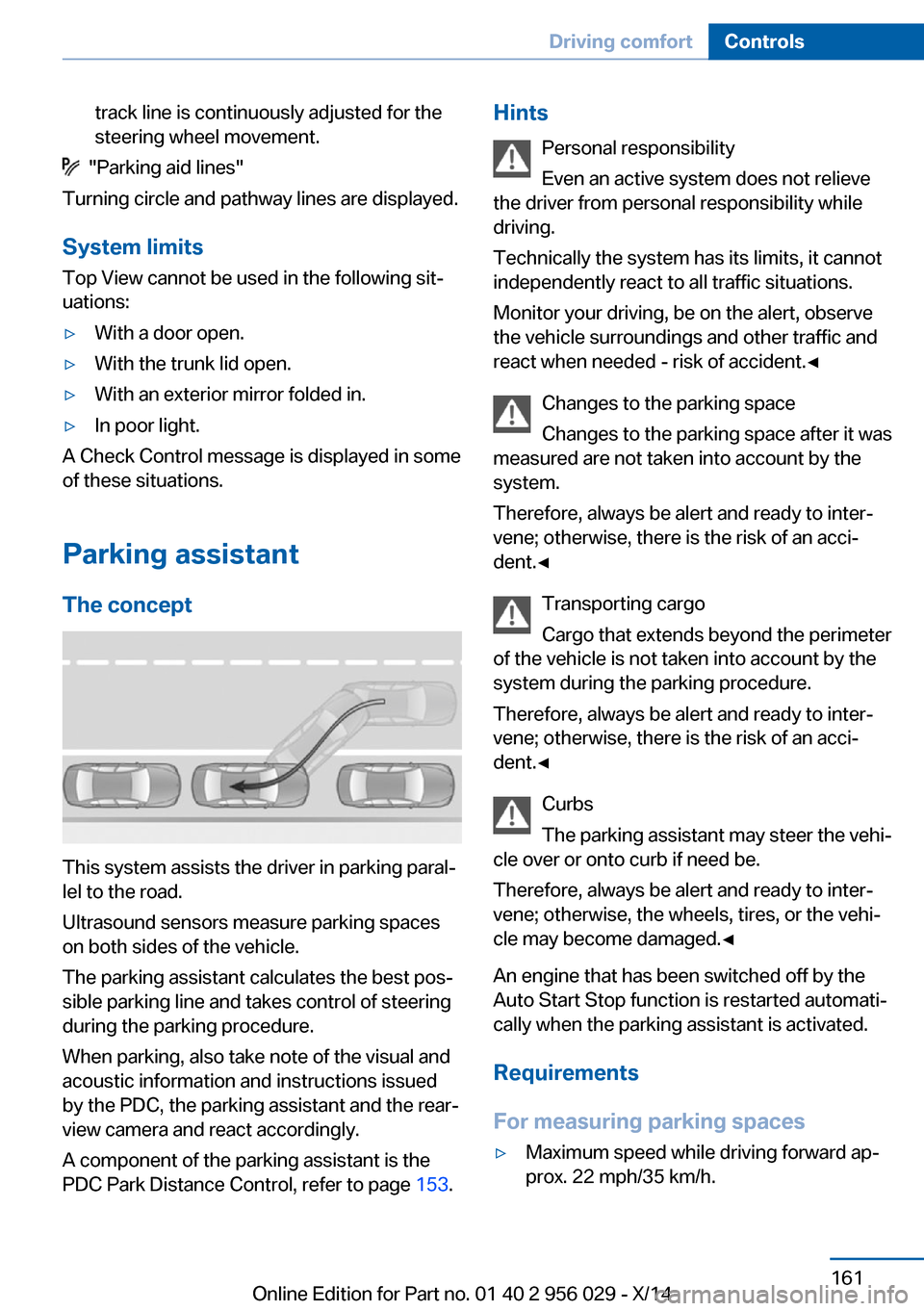
Parking assistant The concept
This system assists the driver in parking paral‐
lel to the road.
Ultrasound sensors measure parking spaces
on both sides of the vehicle.
The parking assistant calculates the best pos‐
sible parking line and takes control of steering
during the parking procedure.
When parking, also take note of the visual and
acoustic information and instructions issued
by the PDC, the parking assistant and the rear‐
view camera and react accordingly.
A component of the parking assistant is the
PDC Park Distance Control, refer to page 153.
Hints
Personal responsibility
Even an active system does not relieve
the driver from personal responsibility while
driving.
Technically the system has its limits, it cannot
independently react to all traffic situations.
Monitor your driving, be on the alert, observe
the vehicle surroundings and other traffic and
react when needed - risk of accident.◀
Changes to the parking space
Changes to the parking space after it was
measured are not taken into account by the system.
Therefore, always be alert and ready to inter‐
vene; otherwise, there is the risk of an acci‐
dent.◀
Transporting cargo
Cargo that extends beyond the perimeter
of the vehicle is not taken into account by the
system during the parking procedure.
Therefore, always be alert and ready to inter‐
vene; otherwise, there is the risk of an acci‐
dent.◀
Curbs
The parking assistant may steer the vehi‐
cle over or onto curb if need be.
Therefore, always be alert and ready to inter‐
vene; otherwise, the wheels, tires, or the vehi‐
cle may become damaged.◀
An engine that has been switched off by the
Auto Start Stop function is restarted automati‐
cally when the parking assistant is activated.
Requirements
For measuring parking spaces▷Maximum speed while driving forward ap‐
prox. 22 mph/35 km/h.Seite 161Driving comfortControls161
Online Edition for Part no. 01 40 2 956 029 - X/14
Page 227 of 265
CoolantVehicle features and optionsThis chapter describes all standard, country-
specific and optional features offered with the
series. It also describes features that are not
necessarily available in your car, e. g., due to
the selected options or country versions. This
also applies to safety-related functions and
systems.
Hints Danger of burns from hot engine
Do not open the cooling system while
the engine is hot; otherwise, esliding coolant
may cause burns.◀
Suitable additives
Only use suitable additives; otherwise,
engine damage may occur. The additives are
harmful to your health.◀
Coolant consists of water and additives.
Not all commercially available additives are
suitable for the vehicle. Information about the
suitable additives are available from the service
center.
Coolant level
General information If there is no Min. and Max. mark in the filler
neck of the coolant reservoir, have the coolant
level checked if needed by your service center
and add coolant as needed.
Depending on the engine installation, the cool‐
ant reservoir is located on the right side or the
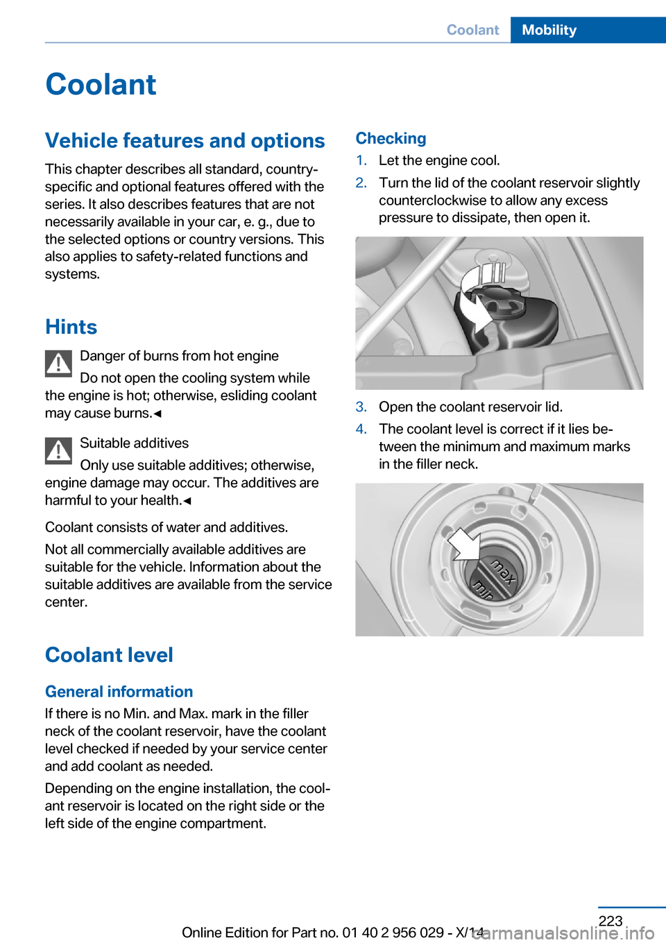
left side of the engine compartment.Checking1.Let the engine cool.2.Turn the lid of the coolant reservoir slightly
counterclockwise to allow any excess
pressure to dissipate, then open it.3.Open the coolant reservoir lid.4.The coolant level is correct if it lies be‐
tween the minimum and maximum marks
in the filler neck.Seite 223CoolantMobility223
Online Edition for Part no. 01 40 2 956 029 - X/14
Page 230 of 265

correspondingly trained personnel and other
authorized persons. Otherwise, use may result
in operating problems for the vehicle.◀
Position
There is an OBD socket on the driver's side for
checking the primary components in the vehi‐
cle's emissions.
Emissions
▷The warning lamp lights up:
Emissions are deteriorating. Have
the vehicle checked as soon as
possible.▷The warning lamp flashes under certain
circumstances:
This indicates that there is excessive mis‐
firing in the engine.
Reduce the vehicle speed and have the
system checked immediately; otherwise,
serious engine misfiring within a brief pe‐
riod can seriously damage emission con‐
trol components, in particular the catalytic
converter.Seite 226MobilityMaintenance226
Online Edition for Part no. 01 40 2 956 029 - X/14
Page 233 of 265
Hints
Because of the long life of these bulbs, the
likelihood of failure is very low. Switching the
lights on and off frequently shortens their life.
If a bulb fails, reel on the front fog lights and
continue the trip with great care. Comply with
local regulations.
Do not perform work/bulb replacement
on xenon headlights
Have any work on the xenon lighting system,
including bulb replacement, performed only by
a service center. Due to the high voltage
present in the system, there is a danger of fatal
injuries if work is carried out improperly.◀
For checking and adjusting headlamp aim,
please contact your BMW center.
Light-emitting diodes (LEDs)
Follow general instructions, refer to page 227.
With Xenon-headlights, the following lights are
designed with LED technology:▷Parking lights and roadside parking lights.▷Turn signals, incl. side indicators▷Daytime running lights
Contact your service center in the event of a
malfunction.
Turning lamp with the Xenon headlight
Follow general instructions, refer to page 227.
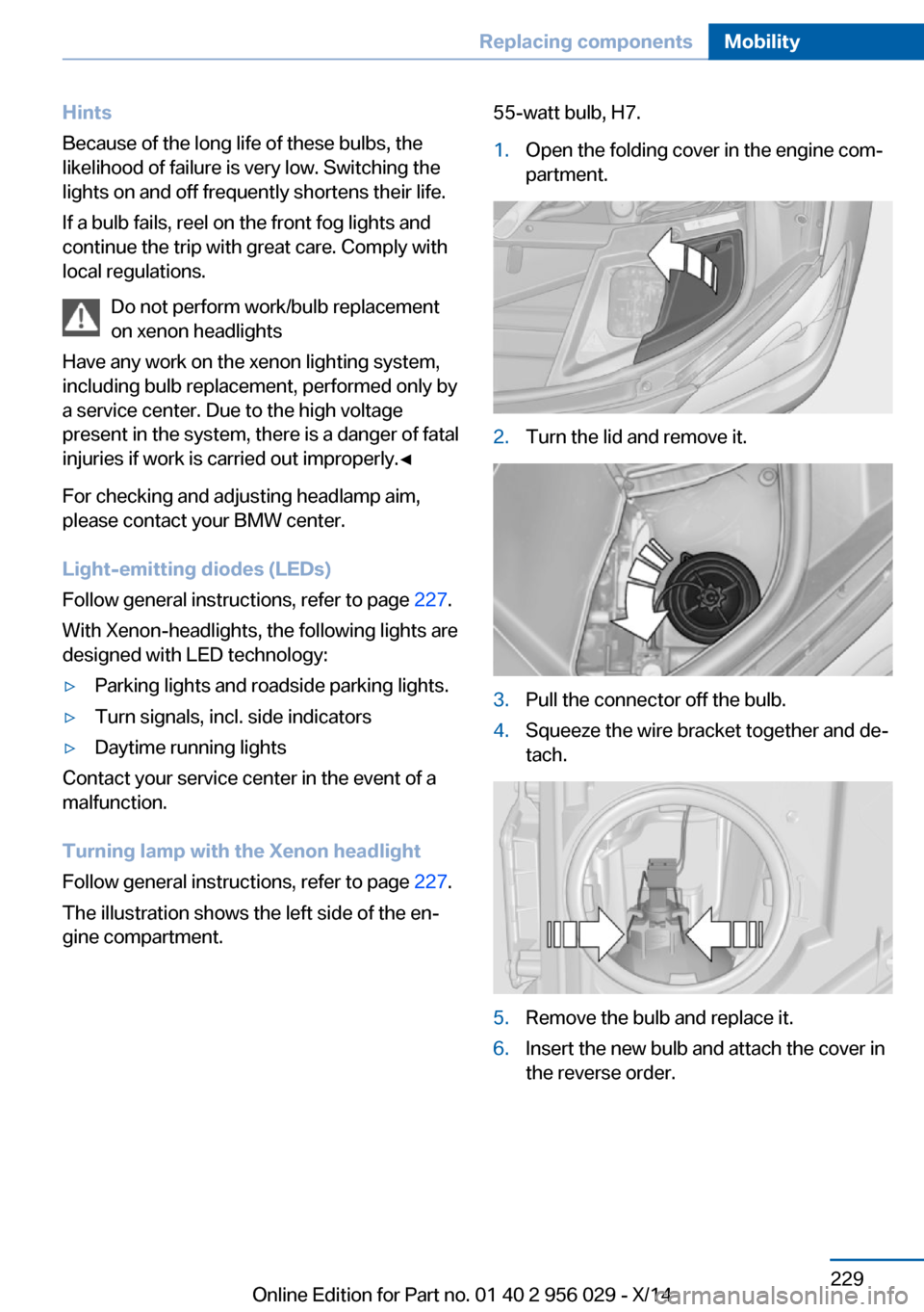
The illustration shows the left side of the en‐
gine compartment.
55-watt bulb, H7.1.Open the folding cover in the engine com‐
partment.2.Turn the lid and remove it.3.Pull the connector off the bulb.4.Squeeze the wire bracket together and de‐
tach.5.Remove the bulb and replace it.6.Insert the new bulb and attach the cover in
the reverse order.Seite 229Replacing componentsMobility229
Online Edition for Part no. 01 40 2 956 029 - X/14
Page 241 of 265
If the first starting attempt is not success‐
ful, wait a few minutes before making an‐
other attempt in order to allow the dis‐
charged battery to recharge.3.Let both engines run for several minutes.4.Disconnect the jumper cables in the re‐
verse order.
Check the battery and recharge if needed.
Tow-starting and towing Note Tow-starting and towing
For towing the vehicle turn, switch off the
Intelligent Safety systems; otherwise malfunc‐
tions of the individual braking systems might
lead to accidents.◀
Transporting your vehicle
Note Your vehicle is not permitted to be towed.
Therefore, contact a service center in the
event of a breakdown.
Do not have the vehicle towed
Have your vehicle transported on a load‐
ing platform only; otherwise, damage may oc‐ cur.◀
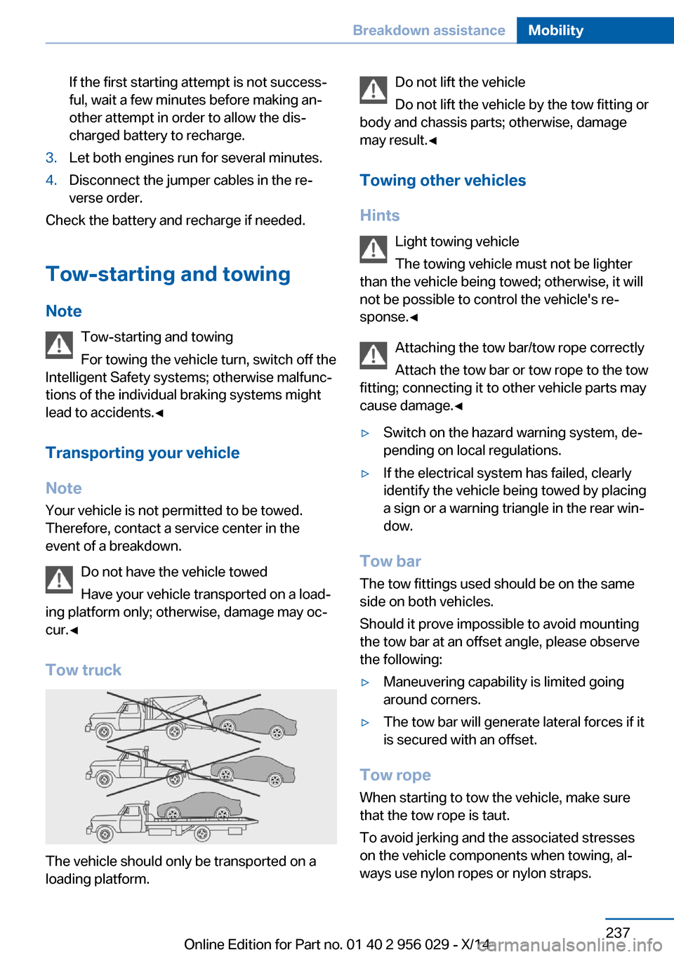
Tow truck
The vehicle should only be transported on a
loading platform.
Do not lift the vehicle
Do not lift the vehicle by the tow fitting or
body and chassis parts; otherwise, damage
may result.◀
Towing other vehicles
Hints Light towing vehicle
The towing vehicle must not be lighter
than the vehicle being towed; otherwise, it will
not be possible to control the vehicle's re‐
sponse.◀
Attaching the tow bar/tow rope correctly
Attach the tow bar or tow rope to the tow
fitting; connecting it to other vehicle parts may
cause damage.◀▷Switch on the hazard warning system, de‐
pending on local regulations.▷If the electrical system has failed, clearly
identify the vehicle being towed by placing
a sign or a warning triangle in the rear win‐
dow.
Tow bar
The tow fittings used should be on the same
side on both vehicles.
Should it prove impossible to avoid mounting
the tow bar at an offset angle, please observe
the following:
▷Maneuvering capability is limited going
around corners.▷The tow bar will generate lateral forces if it
is secured with an offset.
Tow rope
When starting to tow the vehicle, make sure
that the tow rope is taut.
To avoid jerking and the associated stresses
on the vehicle components when towing, al‐
ways use nylon ropes or nylon straps.
Seite 237Breakdown assistanceMobility237
Online Edition for Part no. 01 40 2 956 029 - X/14
Page 244 of 265
In this way, the ignition remains switched
on, and a Check-Control message is dis‐
played.
Do not turn off the ignition in the car
wash
Do not turn off the ignition in the car wash;
otherwise, selector lever position P is en‐
gaged and damages can result.◀
The vehicle cannot be locked from the outside
when in selector lever position N. A signal
sounds when an attempt is made to lock the
vehicle.
To start the engine:
1.Depress the brake pedal.2.Press the Start/Stop button.
Pressing the Start/Stop button without step‐
ping on the brake turns the ignition off.
Selector lever positionSelector lever position P is engaged automati‐
cally:
▷When the ignition is switched off.▷After approx. 15 minutes.
Headlights
▷Do not rub dry and do not use abrasive or
acidic cleansers.▷Soak areas that have been dirtied e. g.,
from insects, with shampoo and wash off
with water.▷Thaw ice with de-icing spray; do not use an
ice scraper.
After washing the vehicle
After washing the vehicle, apply the brakes
briefly to dry them; otherwise, braking action
can be reduced and corrosion of the brake
discs can occur.
Completely remove all residues on the win‐
dows, to minimize loss of visibility due to
smearing and to reduce wiper noises and
wiper blade wear.
Vehicle care
Car care productsBMW recommends using care and cleaning
products from BMW, since these have been
tested and approved.
Car care and cleaning products
Follow the instructions on the container.
When cleaning the interior, open the doors or
windows.
Only use products intended for cleaning vehi‐ cles.
Cleansers can contain substances that are
dangerous and harmful to your health.◀
Vehicle paint Regular care contributes to driving safety and
value retention. Environmental influences in
areas with elevated air pollution or natural con‐
taminants, such as tree resin or pollen can af‐
fect the vehicle's paintwork. Tailor the fre‐
quency and extent of your car care to these
influences.
Aggressive substances such as spilled fuel, oil,
grease or bird droppings, must be removed im‐
mediately to prevent the finish from being al‐
tered or discolored.
Only use respectively approved cleaning and
care products for vehicles with matte finish.
Suitable care products for matte finishes are
available from the service center.
Leather care Remove dust from the leather often, using a
cloth or vacuum cleaner.
Otherwise, particles of dust and road grime
chafe in pores and folds, and lead to increased
wear and premature degradation of the leather
surface.
To guard against discoloration, such as from
clothing, provide leather care roughly every
two months.Seite 240MobilityCare240
Online Edition for Part no. 01 40 2 956 029 - X/14
Page 255 of 265
Battery replacement, vehiclebattery 232
Battery replacement, vehicle remote control 35
Battery, vehicle 232
Belts, safety belts 60
Beverage holder, cu‐ pholder 182
Blinds, sun protection 50
BMW Advanced Diesel 203
BMW Assist, see user's manual for Navigation, En‐
tertainment and Communi‐
cation
BMW maintenance sys‐ tem 225
Bonus range, ECO PRO 194
Bottle holder, refer to Cu‐ pholder 182
Brake assistant 136
Brake assistant, adaptive 136
Brake discs, break-in 186
Brake force display 133
Brake lights, adaptive 133
Brake lights, brake force dis‐ play 133
Brake lights, bulb replace‐ ment 230
Brake pads, break-in 186
Braking, hints 188
Breakdown assis‐ tance 234, 235
Break-in 186
Brightness of Control Dis‐ play 103
Bulb replacement, rear 230
Bulb replacement, see Lamp and bulb replacement 227
Button, RES 147
Button, Start/Stop 73
Bypassing, refer to Jump- starting 235 C
California Proposition 65 Warning 7
Calling up mirror adjust‐ ment 47
Calling up seat adjust‐ ment 47
Calling up steering wheel ad‐ justment 47
Camera, care 242
Camera, rearview cam‐ era 156
Camera, Side View 158
Camera, Top View 160
Can holder, refer to Cu‐ pholder 182
Car battery 232
Car care products 240
Care, displays 242
Care, vehicle 240
Cargo 189
Cargo area, storage compart‐ ments 182
Cargo, securing 190
Cargo straps, securing cargo 190
Car key, refer to Remote con‐ trol 34
Carpet, care 242
Car wash 239
Catalytic converter, refer to Hot exhaust system 186
CBS Condition Based Serv‐ ice 225
CD/Multimedia, see user's manual for Navigation, En‐
tertainment and Communi‐
cation
Center armrest 181
Center console 16
Central locking system 39
Central screen, refer to Con‐ trol Display 18
Changes, technical, refer to Safety 7 Changing parts 227
Changing wheels 231
Changing wheels/tires 214
Chassis number, see vehicle identification number 9
Check Control 90
Checking the engine oil level electronically 220
Checking the oil level elec‐ tronically 220
Children, seating position 69
Children, transporting safely 69
Child restraint fixing sys‐ tem 69
Child restraint fixing system LATCH 70
Child restraint fixing systems, mounting 69
Child safety locks 72
Child seat, mounting 69
Child seats 69
Chrome parts, care 241
Cigarette lighter 174
Cleaning displays 242
Climate control 165
Climate control laminated tinted safety glass 187
Climate control on roof‐ liner 171
Climate control wind‐ shield 187
Clock 95
Closing/opening via door lock 39
Closing/opening with remote control 37
Closing the trunk lid with no- touch activation 45
Clothes hooks 182
Coasting 196
Coasting with engine decou‐ pled, coasting 196
Coasting with idling en‐ gine 196 Seite 251Everything from A to ZReference251
Online Edition for Part no. 01 40 2 956 029 - X/14
Page 257 of 265
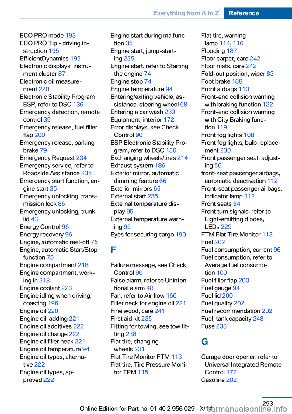
ECO PRO mode 193
ECO PRO Tip - driving in‐ struction 195
EfficientDynamics 195
Electronic displays, instru‐ ment cluster 87
Electronic oil measure‐ ment 220
Electronic Stability Program ESP, refer to DSC 136
Emergency detection, remote control 35
Emergency release, fuel filler flap 200
Emergency release, parking brake 79
Emergency Request 234
Emergency service, refer to Roadside Assistance 235
Emergency start function, en‐ gine start 35
Emergency unlocking, trans‐ mission lock 86
Emergency unlocking, trunk lid 43
Energy Control 96
Energy recovery 96
Engine, automatic reel-off 75
Engine, automatic Start/Stop function 75
Engine compartment 218
Engine compartment, work‐ ing in 218
Engine coolant 223
Engine idling when driving, coasting 196
Engine oil 220
Engine oil, adding 221
Engine oil additives 222
Engine oil change 222
Engine oil filler neck 221
Engine oil temperature 94
Engine oil types, alterna‐ tive 222
Engine oil types, ap‐ proved 222 Engine start during malfunc‐
tion 35
Engine start, jump-start‐ ing 235
Engine start, refer to Starting the engine 74
Engine stop 74
Engine temperature 94
Entering/exiting vehicle, as‐ sistance, steering wheel 68
Entering a car wash 239
Equipment, interior 172
Error displays, see Check Control 90
ESP Electronic Stability Pro‐ gram, refer to DSC 136
Exchanging wheels/tires 214
Exhaust system 186
Exterior mirror, automatic dimming feature 66
Exterior mirrors 65
External start 235
External temperature dis‐ play 95
External temperature warn‐ ing 95
Eyes for securing cargo 190
F
Failure message, see Check Control 90
False alarm, refer to Uninten‐ tional alarm 48
Fan, refer to Air flow 166
Filler neck for engine oil 221
Fine wood, care 241
First aid kit 235
Fitting for towing, see tow fit‐ ting 238
Flat tire, changing wheels 231
Flat Tire Monitor FTM 113
Flat tire, Tire Pressure Moni‐ tor TPM 115 Flat tire, warning
lamp 114, 116
Flooding 187
Floor carpet, care 242
Floor mats, care 242
Fold-out position, wiper 83
Foot brake 188
Front airbags 110
Front-end collision warning with braking function 122
Front-end collision warning with City Braking func‐
tion 119
Front fog lights 108
Front fog lights, bulb replace‐ ment 230
Front passenger seat, adjust‐ ing 56
front-seat passenger airbags, automatic deactivation 112
Front-seat passenger airbags, indicator lamp 112
Front seats 54
Front turn signals, refer to Light-emitting diodes,
LEDs 229
FTM Flat Tire Monitor 113
Fuel 202
Fuel consumption, current 96
Fuel consumption, refer to Average fuel consump‐
tion 100
Fuel filler flap 200
Fuel gauge 94
Fuel lid 200
Fuel quality 202
Fuel recommendation 202
Fuel, tank capacity 248
Fuse 233
G
Garage door opener, refer to Universal Integrated Remote
Control 172
Gasoline 202 Seite 253Everything from A to ZReference253
Online Edition for Part no. 01 40 2 956 029 - X/14