engine BMW 7 SERIES 2014 F02 Owner's Guide
[x] Cancel search | Manufacturer: BMW, Model Year: 2014, Model line: 7 SERIES, Model: BMW 7 SERIES 2014 F02Pages: 265, PDF Size: 5.68 MB
Page 89 of 265
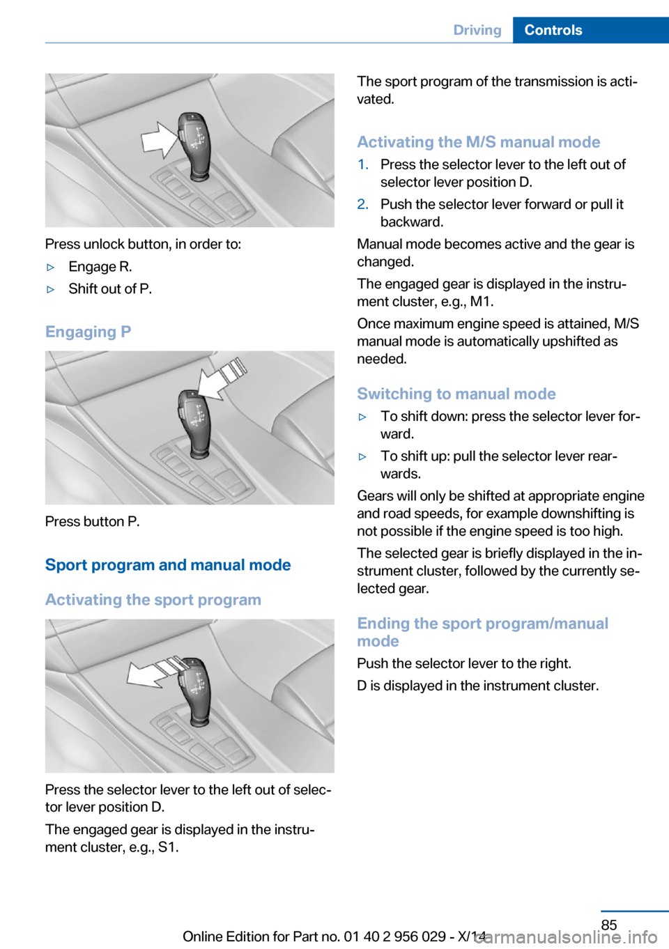
Press unlock button, in order to:
▷Engage R.▷Shift out of P.
Engaging P
Press button P.Sport program and manual mode
Activating the sport program
Press the selector lever to the left out of selec‐
tor lever position D.
The engaged gear is displayed in the instru‐
ment cluster, e.g., S1.
The sport program of the transmission is acti‐
vated.
Activating the M/S manual mode1.Press the selector lever to the left out of
selector lever position D.2.Push the selector lever forward or pull it
backward.
Manual mode becomes active and the gear is
changed.
The engaged gear is displayed in the instru‐
ment cluster, e.g., M1.
Once maximum engine speed is attained, M/S
manual mode is automatically upshifted as
needed.
Switching to manual mode
▷To shift down: press the selector lever for‐
ward.▷To shift up: pull the selector lever rear‐
wards.
Gears will only be shifted at appropriate engine
and road speeds, for example downshifting is
not possible if the engine speed is too high.
The selected gear is briefly displayed in the in‐
strument cluster, followed by the currently se‐
lected gear.
Ending the sport program/manual
mode
Push the selector lever to the right.
D is displayed in the instrument cluster.
Seite 85DrivingControls85
Online Edition for Part no. 01 40 2 956 029 - X/14
Page 90 of 265
Shift paddles
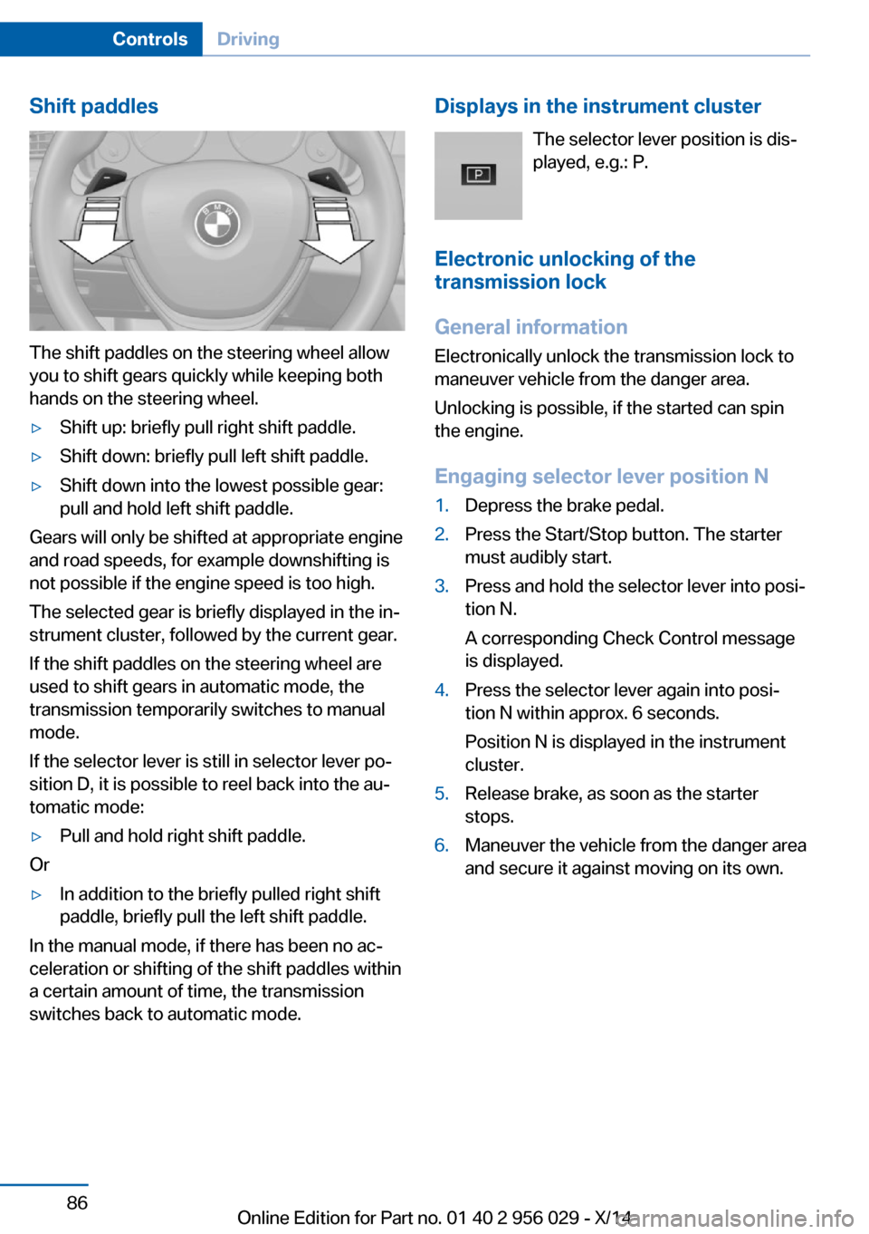
The shift paddles on the steering wheel allow
you to shift gears quickly while keeping both
hands on the steering wheel.
▷Shift up: briefly pull right shift paddle.▷Shift down: briefly pull left shift paddle.▷Shift down into the lowest possible gear:
pull and hold left shift paddle.
Gears will only be shifted at appropriate engine
and road speeds, for example downshifting is
not possible if the engine speed is too high.
The selected gear is briefly displayed in the in‐
strument cluster, followed by the current gear.
If the shift paddles on the steering wheel are
used to shift gears in automatic mode, the
transmission temporarily switches to manual
mode.
If the selector lever is still in selector lever po‐
sition D, it is possible to reel back into the au‐
tomatic mode:
▷Pull and hold right shift paddle.
Or
▷In addition to the briefly pulled right shift
paddle, briefly pull the left shift paddle.
In the manual mode, if there has been no ac‐
celeration or shifting of the shift paddles within
a certain amount of time, the transmission
switches back to automatic mode.
Displays in the instrument cluster
The selector lever position is dis‐played, e.g.: P.
Electronic unlocking of the
transmission lock
General information
Electronically unlock the transmission lock to
maneuver vehicle from the danger area.
Unlocking is possible, if the started can spin
the engine.
Engaging selector lever position N1.Depress the brake pedal.2.Press the Start/Stop button. The starter
must audibly start.3.Press and hold the selector lever into posi‐
tion N.
A corresponding Check Control message
is displayed.4.Press the selector lever again into posi‐
tion N within approx. 6 seconds.
Position N is displayed in the instrument
cluster.5.Release brake, as soon as the starter
stops.6.Maneuver the vehicle from the danger area
and secure it against moving on its own.Seite 86ControlsDriving86
Online Edition for Part no. 01 40 2 956 029 - X/14
Page 91 of 265
DisplaysVehicle features and optionsThis chapter describes all standard, country-
specific and optional features offered with the
series. It also describes features that are notnecessarily available in your car, e. g., due to
the selected options or country versions. This
also applies to safety-related functions and
systems.
Overview, instrument cluster
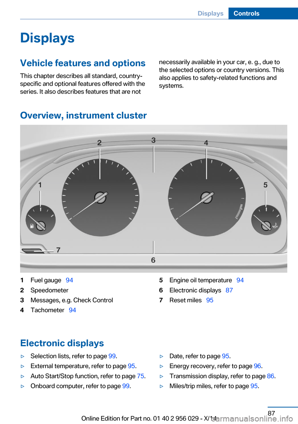
1Fuel gauge 942Speedometer3Messages, e.g. Check Control4Tachometer 945Engine oil temperature 946Electronic displays 877Reset miles 95
Electronic displays
▷Selection lists, refer to page 99.▷External temperature, refer to page 95.▷Auto Start/Stop function, refer to page 75.▷Onboard computer, refer to page 99.▷Date, refer to page 95.▷Energy recovery, refer to page 96.▷Transmission display, refer to page 86.▷Miles/trip miles, refer to page 95.Seite 87DisplaysControls87
Online Edition for Part no. 01 40 2 956 029 - X/14
Page 92 of 265
▷Messages, e.g. Check Control, refer to
page 90.▷Current fuel consumption, refer to
page 96.▷Navigation display, see User's manual for
Navigation, Entertainment and Communi‐
cation.▷Range, refer to page 95.▷Status, Driving Dynamics Control, refer to
page 141.▷Service requirements, refer to page 96.▷Speed limit detection, refer to page 97.▷Time, refer to page 95.
Multifunctional instrument display
The concept
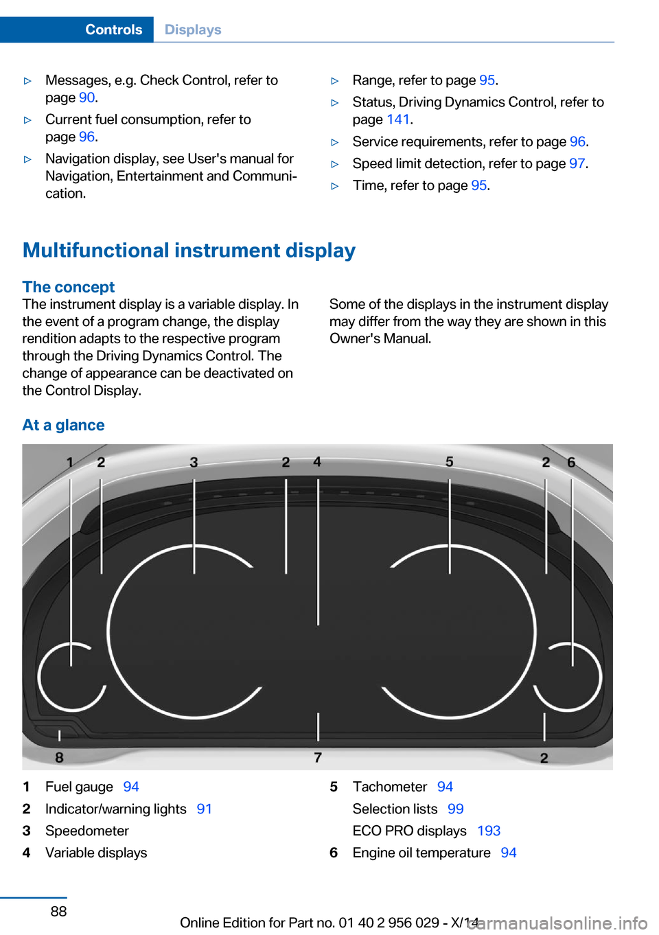
The instrument display is a variable display. In
the event of a program change, the display
rendition adapts to the respective program
through the Driving Dynamics Control. The
change of appearance can be deactivated on
the Control Display.Some of the displays in the instrument display
may differ from the way they are shown in this
Owner's Manual.
At a glance
1Fuel gauge 942Indicator/warning lights 913Speedometer4Variable displays5Tachometer 94
Selection lists 99
ECO PRO displays 1936Engine oil temperature 94Seite 88ControlsDisplays88
Online Edition for Part no. 01 40 2 956 029 - X/14
Page 95 of 265
In addition, an acoustic signal may sound and a
text message may appear on the Control Dis‐
play.
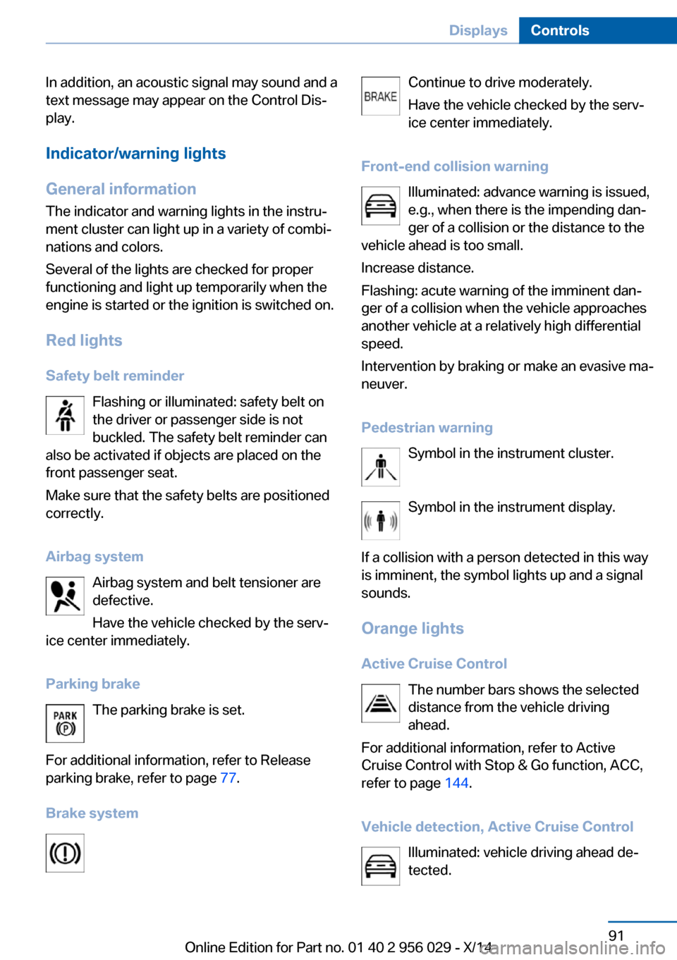
Indicator/warning lights
General information
The indicator and warning lights in the instru‐
ment cluster can light up in a variety of combi‐
nations and colors.
Several of the lights are checked for proper
functioning and light up temporarily when the
engine is started or the ignition is switched on.
Red lights Safety belt reminder Flashing or illuminated: safety belt on
the driver or passenger side is not
buckled. The safety belt reminder can
also be activated if objects are placed on the
front passenger seat.
Make sure that the safety belts are positioned
correctly.
Airbag system Airbag system and belt tensioner are
defective.
Have the vehicle checked by the serv‐
ice center immediately.
Parking brake The parking brake is set.
For additional information, refer to Release
parking brake, refer to page 77.
Brake systemContinue to drive moderately.
Have the vehicle checked by the serv‐ ice center immediately.
Front-end collision warning Illuminated: advance warning is issued,
e.g., when there is the impending dan‐
ger of a collision or the distance to the
vehicle ahead is too small.
Increase distance.
Flashing: acute warning of the imminent dan‐
ger of a collision when the vehicle approaches
another vehicle at a relatively high differential
speed.
Intervention by braking or make an evasive ma‐
neuver.
Pedestrian warning Symbol in the instrument cluster.
Symbol in the instrument display.
If a collision with a person detected in this way
is imminent, the symbol lights up and a signal
sounds.
Orange lights Active Cruise Control The number bars shows the selected
distance from the vehicle driving
ahead.
For additional information, refer to Active
Cruise Control with Stop & Go function, ACC,
refer to page 144.
Vehicle detection, Active Cruise Control Illuminated: vehicle driving ahead de‐
tected.Seite 91DisplaysControls91
Online Edition for Part no. 01 40 2 956 029 - X/14
Page 96 of 265
Flashing: the conditions are not adequate for
operating the system.
The system was deactivated but applies the
brakes until you actively resume control by
pressing on the brake pedal or accelerator
pedal.
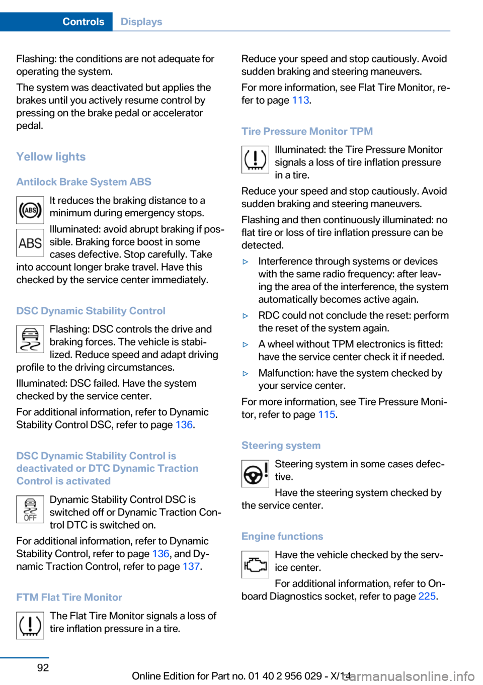
Yellow lights
Antilock Brake System ABS It reduces the braking distance to a
minimum during emergency stops.
Illuminated: avoid abrupt braking if pos‐
sible. Braking force boost in some
cases defective. Stop carefully. Take
into account longer brake travel. Have this
checked by the service center immediately.
DSC Dynamic Stability Control Flashing: DSC controls the drive and
braking forces. The vehicle is stabi‐
lized. Reduce speed and adapt driving
profile to the driving circumstances.
Illuminated: DSC failed. Have the system
checked by the service center.
For additional information, refer to Dynamic
Stability Control DSC, refer to page 136.
DSC Dynamic Stability Control is
deactivated or DTC Dynamic Traction
Control is activated
Dynamic Stability Control DSC is
switched off or Dynamic Traction Con‐
trol DTC is switched on.
For additional information, refer to Dynamic
Stability Control, refer to page 136, and Dy‐
namic Traction Control, refer to page 137.
FTM Flat Tire Monitor The Flat Tire Monitor signals a loss of
tire inflation pressure in a tire.Reduce your speed and stop cautiously. Avoid
sudden braking and steering maneuvers.
For more information, see Flat Tire Monitor, re‐
fer to page 113.
Tire Pressure Monitor TPM Illuminated: the Tire Pressure Monitor
signals a loss of tire inflation pressure
in a tire.
Reduce your speed and stop cautiously. Avoid
sudden braking and steering maneuvers.
Flashing and then continuously illuminated: no
flat tire or loss of tire inflation pressure can be
detected.▷Interference through systems or devices
with the same radio frequency: after leav‐
ing the area of the interference, the system
automatically becomes active again.▷RDC could not conclude the reset: perform
the reset of the system again.▷A wheel without TPM electronics is fitted:
have the service center check it if needed.▷Malfunction: have the system checked by
your service center.
For more information, see Tire Pressure Moni‐
tor, refer to page 115.
Steering system Steering system in some cases defec‐
tive.
Have the steering system checked by
the service center.
Engine functions Have the vehicle checked by the serv‐ice center.
For additional information, refer to On-
board Diagnostics socket, refer to page 225.
Seite 92ControlsDisplays92
Online Edition for Part no. 01 40 2 956 029 - X/14
Page 98 of 265
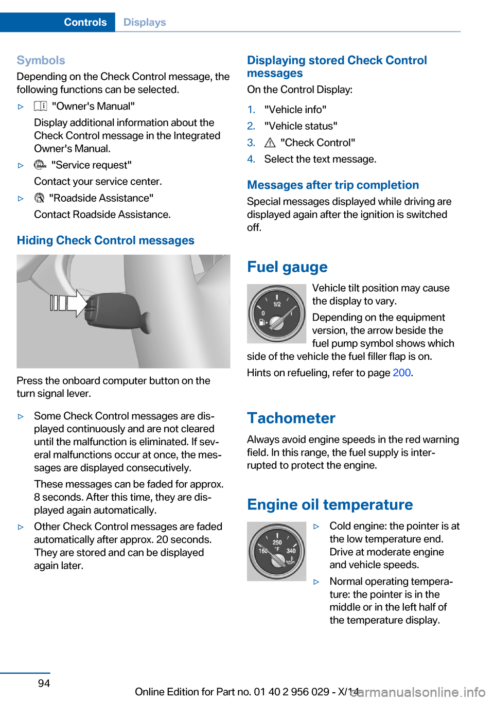
Symbols
Depending on the Check Control message, the
following functions can be selected.▷ "Owner's Manual"
Display additional information about the
Check Control message in the Integrated
Owner's Manual.▷ "Service request"
Contact your service center.▷ "Roadside Assistance"
Contact Roadside Assistance.
Hiding Check Control messages
Press the onboard computer button on the
turn signal lever.
▷Some Check Control messages are dis‐
played continuously and are not cleared
until the malfunction is eliminated. If sev‐
eral malfunctions occur at once, the mes‐
sages are displayed consecutively.
These messages can be faded for approx.
8 seconds. After this time, they are dis‐
played again automatically.▷Other Check Control messages are faded
automatically after approx. 20 seconds.
They are stored and can be displayed
again later.Displaying stored Check Control
messages
On the Control Display:1."Vehicle info"2."Vehicle status"3. "Check Control"4.Select the text message.
Messages after trip completion Special messages displayed while driving are
displayed again after the ignition is switched
off.
Fuel gauge Vehicle tilt position may cause
the display to vary.
Depending on the equipment
version, the arrow beside the
fuel pump symbol shows which
side of the vehicle the fuel filler flap is on.
Hints on refueling, refer to page 200.
Tachometer Always avoid engine speeds in the red warning
field. In this range, the fuel supply is inter‐
rupted to protect the engine.
Engine oil temperature
▷Cold engine: the pointer is at
the low temperature end.
Drive at moderate engine
and vehicle speeds.▷Normal operating tempera‐
ture: the pointer is in the
middle or in the left half of
the temperature display.Seite 94ControlsDisplays94
Online Edition for Part no. 01 40 2 956 029 - X/14
Page 99 of 265
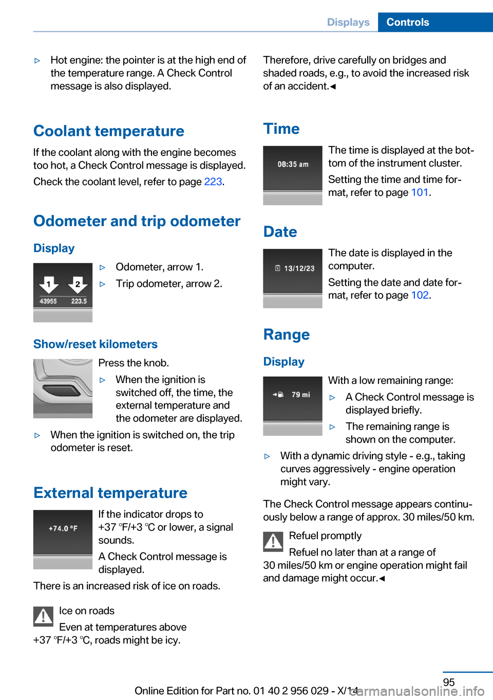
▷Hot engine: the pointer is at the high end of
the temperature range. A Check Control
message is also displayed.
Coolant temperature
If the coolant along with the engine becomes
too hot, a Check Control message is displayed.
Check the coolant level, refer to page 223.
Odometer and trip odometer Display
▷Odometer, arrow 1.▷Trip odometer, arrow 2.
Show/reset kilometers Press the knob.
▷When the ignition is
switched off, the time, the
external temperature and
the odometer are displayed.▷When the ignition is switched on, the trip
odometer is reset.
External temperature
If the indicator drops to
+37 ℉/+3 ℃ or lower, a signal
sounds.
A Check Control message is displayed.
There is an increased risk of ice on roads.
Ice on roads
Even at temperatures above
+37 ℉/+3 ℃, roads might be icy.
Therefore, drive carefully on bridges and
shaded roads, e.g., to avoid the increased risk
of an accident.◀
Time The time is displayed at the bot‐
tom of the instrument cluster.
Setting the time and time for‐
mat, refer to page 101.
Date The date is displayed in the
computer.
Setting the date and date for‐
mat, refer to page 102.
Range
Display With a low remaining range:▷A Check Control message is
displayed briefly.▷The remaining range is
shown on the computer.▷With a dynamic driving style - e.g., taking
curves aggressively - engine operation
might vary.
The Check Control message appears continu‐
ously below a range of approx. 30 miles/50 km.
Refuel promptly
Refuel no later than at a range of
30 miles/50 km or engine operation might fail
and damage might occur.◀
Seite 95DisplaysControls95
Online Edition for Part no. 01 40 2 956 029 - X/14
Page 104 of 265
Not for a multi-functional instrument dis‐
play.▷Time of arrival.
When destination guidance is activated in
the navigation system.▷Distance to destination.
When destination guidance is activated in
the navigation system.▷ECO PRO bonus range.
Adjusting the info display
Depending on the vehicle equipment version,
you can select what information from the com‐
puter is to be displayed on the info display of
the instrument cluster.
On the Control Display:
1."Settings"2."Instrument cluster"3.Select the desired displays.
Information in detail
Range
Displays the estimated cruising range available
with the remaining fuel.
It is calculated based on your driving style over
the last 20 miles/30 km.
Average fuel consumption
The average fuel consumption is calculated for
the period while the engine is running.
The average fuel consumption is calculated for
the distance traveled since the last reset by the
computer.
Average speed
Periods in which the vehicle is parked with the
engine manually stopped are not included in
the calculation of the average speed.
Resetting average values
Press and hold the onboard computer button
on the turn signal lever.
Distance to destination
The distance remaining to the destination is
displayed if a destination is entered in the navi‐
gation system before the trip is started.
The distance to the destination is adopted au‐
tomatically.
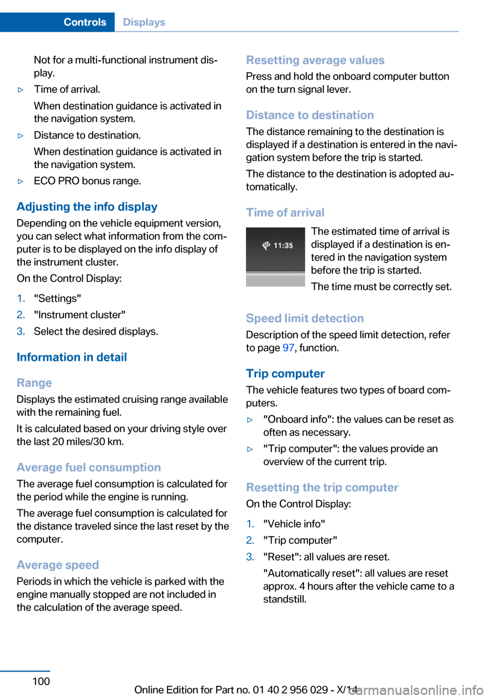
Time of arrival The estimated time of arrival is
displayed if a destination is en‐
tered in the navigation system
before the trip is started.
The time must be correctly set.
Speed limit detection Description of the speed limit detection, refer
to page 97, function.
Trip computer The vehicle features two types of board com‐
puters.▷"Onboard info": the values can be reset as
often as necessary.▷"Trip computer": the values provide an
overview of the current trip.
Resetting the trip computer
On the Control Display:
1."Vehicle info"2."Trip computer"3."Reset": all values are reset.
"Automatically reset": all values are reset
approx. 4 hours after the vehicle came to a
standstill.Seite 100ControlsDisplays100
Online Edition for Part no. 01 40 2 956 029 - X/14
Page 118 of 265
3. "Perform reset"4.Start the engine - do not drive off.5.Start the initialization with "Perform reset".6.Drive away.
The initialization is completed while driving,
which can be interrupted at any time.
The initialization automatically continues when
driving resumes.
Indication of a flat tire The yellow warning lamp lights up. A
Check Control message is displayed.
There is a flat tire or a major loss in tire
inflation pressure.
1.Reduce your speed and stop cautiously.
Avoid sudden braking and steering maneu‐
vers.2.Check whether the vehicle is fitted with
regular tires or run-flat tires.
Run-flat tires, refer to page 216, are la‐
beled with a circular symbol containing the
letters RSC marked on the tire's sidewall.
Do not continue driving without run-flat
tires
Do not continue driving if the vehicle is not
equipped with run-flat tires; continued driving
may result in serious accidents.◀
When a flat tire is indicated, DSC Dynamic Sta‐
bility Control is switched on if needed.
System limits Sudden tire damage
Sudden serious tire damage caused by
external circumstances cannot be recognized
in advance.◀
A natural, even tire inflation pressure loss in all
four tires will not be recognized. Therefore,
check the tire inflation pressure regularly.
The system could be delayed or malfunction in
the following situations:
▷When the system has not been initialized.▷When driving on a snowy or slippery road
surface.▷Sporty driving style: spinning traction
wheels, high lateral acceleration (drifting).▷When driving with snow chains.
Actions in the event of a flat tire
Normal tires
1.Identify the damaged tire.
Do this by checking the air pressure in all
four tires.
If the tire inflation pressure in all four tires
is correct, the Flat Tire Monitor may not
have been initialized. In this case, initialize
the system.
If an identification is not possible, please
contact the service center.2.Fix the flat tire.
Run-flat tires
Maximum speed
You may continue driving with a damaged tire
at speeds up to 50 mph/80 km/h.
Continued driving with a flat tire
If continuing to drive with a damaged tire:
1.Avoid sudden braking and steering maneu‐
vers.2.Do not exceed a speed of 50 mph/80 km/h.3.Check the air pressure in all four tires at
the next opportunity.
If the tire inflation pressure in all four tires
is correct, the Flat Tire Monitor may not
have been initialized. In this case, initialize
the system.
Possible driving distance with complete loss of
tire inflation pressure:
Seite 114ControlsSafety114
Online Edition for Part no. 01 40 2 956 029 - X/14