remote control BMW 7 SERIES 2014 F02 Owner's Guide
[x] Cancel search | Manufacturer: BMW, Model Year: 2014, Model line: 7 SERIES, Model: BMW 7 SERIES 2014 F02Pages: 265, PDF Size: 5.68 MB
Page 78 of 265
▷When the vehicle is locked using the cen‐
tral locking system.▷Shortly before the battery is discharged
completely, so that the engine can still be
started.
The radio-ready state remains active if, e.g.,
the ignition is automatically switched off for the
following reasons:
▷Opening or closing the driver's door.▷Unfastening of the driver's safety belt.▷When automatically switching from low
beams to parking lights.
Starting the engine
Hints Enclosed areas
Do not let the engine run in enclosed
areas, since breathing in exhaust fumes may
lead to loss of consciousness and death. The
exhaust gases contain carbon monoxide, an
odorless and colorless but highly toxic gas.◀
Unattended vehicle
Do not leave the vehicle unattended with
the engine running; doing so poses a risk of
danger.
Before leaving the vehicle with the engine run‐
ning, set the parking brake and place the trans‐
mission in selector lever position P or N to pre‐
vent the vehicle from moving.◀
Repeated starting in quick succession
Avoid trying to start the vehicle repeat‐
edly and in quick succession. Otherwise, the fuel is not burned or is inadequately burned,
posing a risk of overheating and damage to the
catalytic converter.◀
Do not wait for the engine to warm-up while
the vehicle remains stationary. Start driving at
moderate engine speeds.
Diesel engine
If the engine is cold and temperatures are be‐
low approx. 32 ℉/0 ℃, the start process may
be delayed somewhat due to automatic pre‐
heating.
A Check Control message is displayed.
Starting the engine Press on the brake pedal and
press the Start/Stop button.
The engine is cranked until it
starts.
Engine stop Hints Take the remote control with youTake the remote control with you when
leaving the vehicle so that children, e.g., can‐
not start the engine.◀
Apply parking brake and further secure
the vehicle if needed.
Set the parking brake firmly when parking; oth‐
erwise, the vehicle could roll. On steep upward
and downward inclines, further secure the ve‐
hicle, e.g., by turning the steering wheel in the
direction of the curb.◀
Before driving into a car wash
So that the vehicle can roll into a car wash ob‐
serve instructions for going into an automatic
car wash, refer to page 239.
Switching off the engine1.Engage transmission position P with the
vehicle stopped.2.Press the Start/Stop button.
The engine is switched off.
The radio-ready state is switched on.3.Set the parking brake.Seite 74ControlsDriving74
Online Edition for Part no. 01 40 2 956 029 - X/14
Page 81 of 265
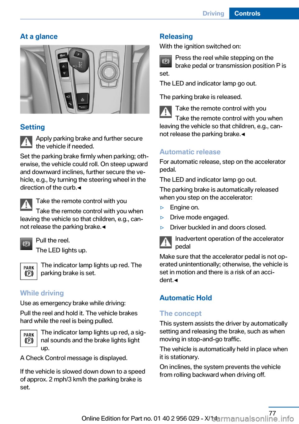
At a glance
SettingApply parking brake and further secure
the vehicle if needed.
Set the parking brake firmly when parking; oth‐
erwise, the vehicle could roll. On steep upward
and downward inclines, further secure the ve‐
hicle, e.g., by turning the steering wheel in the
direction of the curb.◀
Take the remote control with you
Take the remote control with you when
leaving the vehicle so that children, e.g., can‐
not release the parking brake.◀
Pull the reel.
The LED lights up.
The indicator lamp lights up red. The
parking brake is set.
While driving
Use as emergency brake while driving:
Pull the reel and hold it. The vehicle brakes
hard while the reel is being pulled.
The indicator lamp lights up red, a sig‐
nal sounds and the brake lights light
up.
A Check Control message is displayed.
If the vehicle is slowed down down to a speed of approx. 2 mph/3 km/h the parking brake is
set.
Releasing
With the ignition switched on:
Press the reel while stepping on the
brake pedal or transmission position P is
set.
The LED and indicator lamp go out.
The parking brake is released. Take the remote control with you
Take the remote control with you when
leaving the vehicle so that children, e.g., can‐
not release the parking brake.◀
Automatic release For automatic release, step on the accelerator
pedal.
The LED and indicator lamp go out.
The parking brake is automatically released
when you step on the accelerator:▷Engine on.▷Drive mode engaged.▷Driver buckled in and doors closed.
Inadvertent operation of the accelerator
pedal
Make sure that the accelerator pedal is not op‐
erated unintentionally; otherwise, the vehicle is
set in motion and there is a risk of an acci‐
dent.◀
Automatic Hold
The concept This system assists the driver by automatically
setting and releasing the brake, such as when
moving in stop-and-go traffic.
The vehicle is automatically held in place when
it is stationary.
On inclines, the system prevents the vehicle
from rolling backward when driving off.
Seite 77DrivingControls77
Online Edition for Part no. 01 40 2 956 029 - X/14
Page 83 of 265
Take the remote control with you
Take the remote control with you when
leaving the vehicle so that children, e.g., can‐
not release the parking brake.◀
Malfunction
In the event of a failure or malfunction of the
parking brake, secure the vehicle against roll‐
ing using a wheel chock, e.g., when leaving it.
Manual release Before releasing, secure the vehicle
against rolling
Before releasing the parking brake manually,
and whenever you park the vehicle with the
parking brake released, ensure that position P
of the Steptronic transmission is set.
Secure the vehicle in a manner appropriate to
the inclination of the road, e.g., with a wheel
chock; otherwise, there is a danger of an acci‐
dent and injuries if the vehicle rolls uninten‐
tionally.◀
The parking brake can be released manually in
the event of a power failure or electrical fault.
Unlocking Have the malfunction corrected
If the parking brake has been released
manually in response to a malfunction, only
technicians can return it to operation.
Have the malfunction corrected by your serv‐
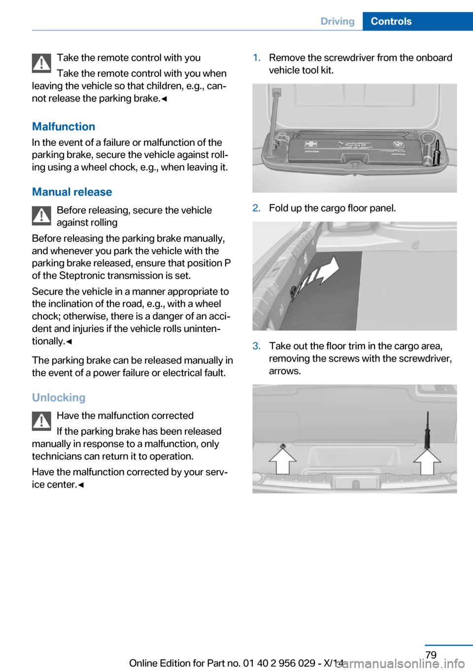
ice center.◀1.Remove the screwdriver from the onboard
vehicle tool kit.2.Fold up the cargo floor panel.3.Take out the floor trim in the cargo area,
removing the screws with the screwdriver,
arrows.Seite 79DrivingControls79
Online Edition for Part no. 01 40 2 956 029 - X/14
Page 100 of 265
Displaying the cruising rangeDepending on your vehicle's optional features,
the range can also be displayed as bar in the
instrument cluster.1."Settings"2."Instrument cluster"3."Additional indicators"
Range when destination guidance is
activated in the navigation system
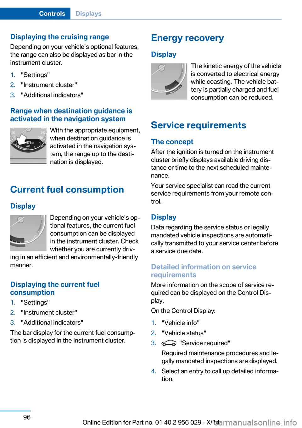
With the appropriate equipment,
when destination guidance is
activated in the navigation sys‐
tem, the range up to the desti‐
nation is displayed.
Current fuel consumption
Display Depending on your vehicle's op‐
tional features, the current fuel
consumption can be displayed
in the instrument cluster. Check
whether you are currently driv‐
ing in an efficient and environmentally-friendly
manner.
Displaying the current fuel
consumption
1."Settings"2."Instrument cluster"3."Additional indicators"
The bar display for the current fuel consump‐
tion is displayed in the instrument cluster.
Energy recovery
Display The kinetic energy of the vehicle
is converted to electrical energy while coasting. The vehicle bat‐
tery is partially charged and fuel
consumption can be reduced.
Service requirements The concept
After the ignition is turned on the instrument
cluster briefly displays available driving dis‐
tance or time to the next scheduled mainte‐
nance.
Your service specialist can read the current
service requirements from your remote con‐
trol.
Display
Data regarding the service status or legally
mandated vehicle inspections are automati‐
cally transmitted to your service center before
a service due date.
Detailed information on service
requirements
More information on the scope of service re‐
quired can be displayed on the Control Dis‐
play.
On the Control Display:1."Vehicle info"2."Vehicle status"3. "Service required"
Required maintenance procedures and le‐
gally mandated inspections are displayed.4.Select an entry to call up detailed informa‐
tion.Seite 96ControlsDisplays96
Online Edition for Part no. 01 40 2 956 029 - X/14
Page 176 of 265
Interior equipmentVehicle features and optionsThis chapter describes all standard, country-
specific and optional features offered with the
series. It also describes features that are not
necessarily available in your car, e. g., due to
the selected options or country versions. This
also applies to safety-related functions and
systems.
Universal Integrated RemoteControl
The concept
The universal garage door opener can operate
up to 3 functions of remote-controlled sys‐
tems such as garage door drives or lighting
systems. The universal garage door opener re‐
places up to 3 different hand-held transmitters.
To operate the remote control, the buttons on
the interior rearview mirror must be program‐
med with the desired functions. The hand-held
transmitter for the particular system is required
in order to program the remote control.
During programming
During programming and before activat‐
ing a device using the universal garage door
opener, ensure that there are no people, ani‐
mals or objects in the area of the remote-con‐
trolled device; otherwise, there is a risk of in‐
jury or damage.
Also follow the safety instructions of the hand-
held transmitter.◀
Before selling the vehicle, delete the stored
functions for the sake of security.
Compatibility If this symbol is printed on the packag‐
ing or in the instructions of the system
to be controlled, the system is gener‐ally compatible with the universal garage door
opener.
If you have any questions, please contact:▷Your service center.▷www.homelink.com on the Internet.
HomeLink is a registered trademark of Gentex
Corporation.
Control elements on the interior
rearview mirror
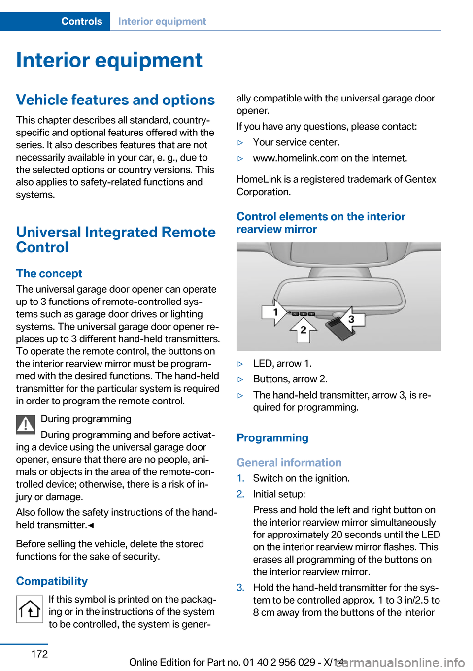
▷LED, arrow 1.▷Buttons, arrow 2.▷The hand-held transmitter, arrow 3, is re‐
quired for programming.
Programming
General information
1.Switch on the ignition.2.Initial setup:
Press and hold the left and right button on
the interior rearview mirror simultaneously
for approximately 20 seconds until the LED
on the interior rearview mirror flashes. This
erases all programming of the buttons on
the interior rearview mirror.3.Hold the hand-held transmitter for the sys‐
tem to be controlled approx. 1 to 3 in/2.5 to
8 cm away from the buttons of the interiorSeite 172ControlsInterior equipment172
Online Edition for Part no. 01 40 2 956 029 - X/14
Page 178 of 265
then be controlled by the button on the in‐
terior rearview mirror.
If the LED does not flash faster after at
least 60 seconds, change the distance and
repeat the step. Several more attempts at
different distances may be necessary. Wait
at least 15 seconds between attempts.
Canada: if programming with the hand-
held transmitter was interrupted, hold
down the interior rearview mirror button
and repeatedly press and release the
hand-held transmitter button for 2 sec‐
onds.
Controls
Before operation
Before operating a system using the uni‐
versal garage door opener, ensure that there are no people, animals, or objects within the
range of movement of the remote-controlled
system; otherwise, there is a risk of injury or
damage.
Also follow the safety instructions of the hand-
held transmitter.◀
The system, such as the garage door, can be
operated using the button on the interior rear‐
view mirror while the engine is running or when
the ignition is started. To do this, hold down
the button within receiving range of the system
until the function is activated. The interior rear‐ view mirror LED stays lit while the wireless sig‐
nal is being transmitted.
Deleting stored functions Press and hold the left and right button on the
interior rearview mirror simultaneously for ap‐
proximately 20 seconds until the LED flashes
rapidly. All stored functions are deleted. The
functions cannot be deleted individually.
Sun visor
Glare shieldFold the sun visor down or up.
Vanity mirror A vanity mirror is located in the sun visor be‐
hind a cover. When the cover is opened, the
mirror lighting switches on.
Ashtray/cigarette lighter
Front
Opening
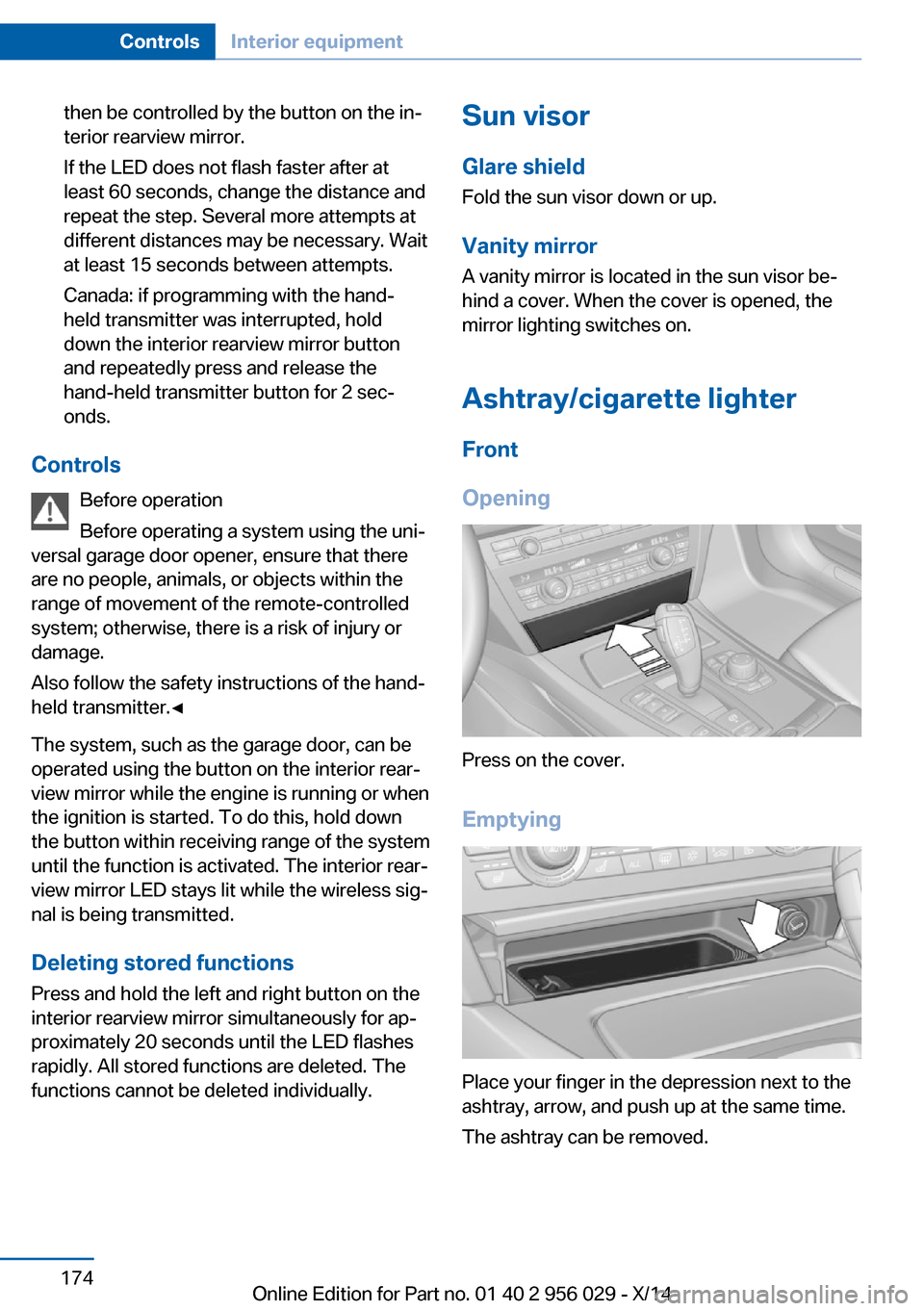
Press on the cover.
Emptying
Place your finger in the depression next to the
ashtray, arrow, and push up at the same time.
The ashtray can be removed.
Seite 174ControlsInterior equipment174
Online Edition for Part no. 01 40 2 956 029 - X/14
Page 179 of 265
LighterPush in the lighter.
The lighter can be removed as
soon as it pops back out.
Danger of burns
Only hold the hot lighter by its knob; oth‐
erwise, there is a danger of getting burned.
Switch off the ignition and take the remote
control with you when leaving the vehicle so
that children cannot use the lighter and burn
themselves.◀
Replace the cover after use
Reinsert the lighter or socket cover after
use, otherwise objects may get into the lighter
socket or fixture and cause a short circuit.◀
Rear
Opening
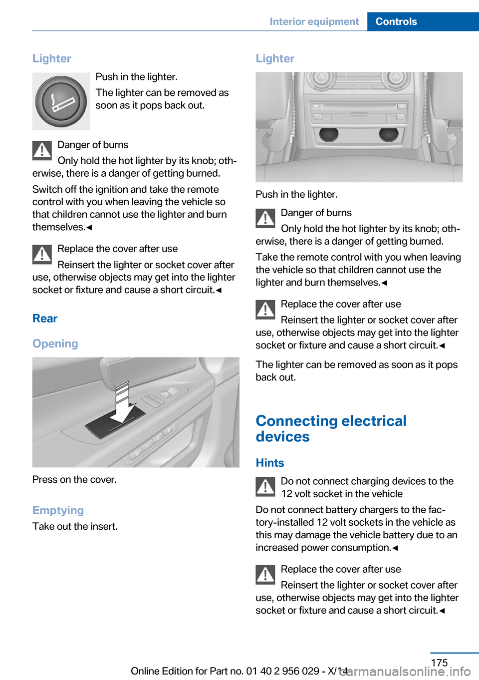
Press on the cover.
Emptying Take out the insert.
Lighter
Push in the lighter.
Danger of burns
Only hold the hot lighter by its knob; oth‐
erwise, there is a danger of getting burned.
Take the remote control with you when leaving
the vehicle so that children cannot use the
lighter and burn themselves.◀
Replace the cover after use
Reinsert the lighter or socket cover after
use, otherwise objects may get into the lighter
socket or fixture and cause a short circuit.◀
The lighter can be removed as soon as it pops
back out.
Connecting electricaldevices
Hints Do not connect charging devices to the
12 volt socket in the vehicle
Do not connect battery chargers to the fac‐
tory-installed 12 volt sockets in the vehicle as
this may damage the vehicle battery due to an
increased power consumption.◀
Replace the cover after use
Reinsert the lighter or socket cover after
use, otherwise objects may get into the lighter
socket or fixture and cause a short circuit.◀
Seite 175Interior equipmentControls175
Online Edition for Part no. 01 40 2 956 029 - X/14
Page 185 of 265
The top cover opens automatically.Closing the top cover
Press the cover closed.
Driver's side
Note Close the glove compartment again im‐
mediately
Close the glove compartment immediately af‐ ter use while driving; otherwise, injury may oc‐
cur during accidents.◀
Opening
Pull the handle.
ClosingFold cover closed.
Center armrest
Front
A storage compartment is located in the center
armrest between the front seats.
Opening
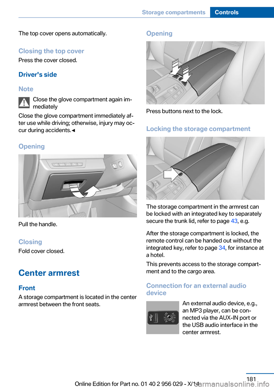
Press buttons next to the lock.
Locking the storage compartment
The storage compartment in the armrest can
be locked with an integrated key to separately
secure the trunk lid, refer to page 43, e.g.
After the storage compartment is locked, the
remote control can be handed out without the
integrated key, refer to page 34, for instance at
a hotel.
This prevents access to the storage compart‐
ment and to the cargo area.
Connection for an external audio
device
An external audio device, e.g.,
an MP3 player, can be con‐
nected via the AUX-IN port or
the USB audio interface in the center armrest.
Seite 181Storage compartmentsControls181
Online Edition for Part no. 01 40 2 956 029 - X/14
Page 229 of 265
MaintenanceVehicle features and options
This chapter describes all standard, country-
specific and optional features offered with the
series. It also describes features that are not
necessarily available in your car, e. g., due to
the selected options or country versions. This
also applies to safety-related functions and
systems.
BMW maintenance system
The maintenance system indicates required
maintenance measures, and thereby provides
support in maintaining road safety and the op‐
erational reliability of the vehicle.
Condition Based Service
CBS
Sensors and special algorithms take into ac‐
count the driving conditions of your vehicle.
Based on this, Condition Based Service recog‐
nizes the maintenance requirements.
The system makes it possible to adapt the
amount of maintenance corresponding to your
user profile.
Details on the service requirements, refer to
page 96, can be displayed on the Control Dis‐
play.
Service data in the remote control Information on the required maintenance is
continuously stored in the remote control.
Your service center will read out this data and
suggest the right array of service procedures
for your vehicle.
Therefore, hand your service specialist the re‐
mote control with which the vehicle was driven
most recently.Storage periods
Storage periods during which the vehicle bat‐
tery was disconnected are not taken into ac‐
count.
If this occurs, have a service center update the
time-dependent maintenance procedures,
such as checking brake fluid and, if needed,
changing the engine oil and the microfilter/
activated-charcoal filter.
Service and Warranty
Information Booklet for US
models and Warranty and
Service Guide Booklet for
Canadian models
Please consult your Service and Warranty In‐
formation Booklet for US models and Warranty
and Service Guide Booklet for Canadian mod‐ els for additional information on service re‐
quirements.
Maintenance and repair should be performed
by your service center. Make sure to have reg‐
ular maintenance procedures recorded in the
vehicle's Service and Warranty Information
Booklet for US models, and in the Warranty
and Service Guide Booklet for Canadian mod‐
els. These entries are proof of regular mainte‐
nance.
Socket for OBD Onboard
Diagnosis
Note Socket for Onboard Diagnosis
The socket for onboard diagnostics may
only be used by the service center or a work‐
shop that operates in accordance with the
specifications of the vehicle manufacturer withSeite 225MaintenanceMobility225
Online Edition for Part no. 01 40 2 956 029 - X/14
Page 255 of 265
Battery replacement, vehiclebattery 232
Battery replacement, vehicle remote control 35
Battery, vehicle 232
Belts, safety belts 60
Beverage holder, cu‐ pholder 182
Blinds, sun protection 50
BMW Advanced Diesel 203
BMW Assist, see user's manual for Navigation, En‐
tertainment and Communi‐
cation
BMW maintenance sys‐ tem 225
Bonus range, ECO PRO 194
Bottle holder, refer to Cu‐ pholder 182
Brake assistant 136
Brake assistant, adaptive 136
Brake discs, break-in 186
Brake force display 133
Brake lights, adaptive 133
Brake lights, brake force dis‐ play 133
Brake lights, bulb replace‐ ment 230
Brake pads, break-in 186
Braking, hints 188
Breakdown assis‐ tance 234, 235
Break-in 186
Brightness of Control Dis‐ play 103
Bulb replacement, rear 230
Bulb replacement, see Lamp and bulb replacement 227
Button, RES 147
Button, Start/Stop 73
Bypassing, refer to Jump- starting 235 C
California Proposition 65 Warning 7
Calling up mirror adjust‐ ment 47
Calling up seat adjust‐ ment 47
Calling up steering wheel ad‐ justment 47
Camera, care 242
Camera, rearview cam‐ era 156
Camera, Side View 158
Camera, Top View 160
Can holder, refer to Cu‐ pholder 182
Car battery 232
Car care products 240
Care, displays 242
Care, vehicle 240
Cargo 189
Cargo area, storage compart‐ ments 182
Cargo, securing 190
Cargo straps, securing cargo 190
Car key, refer to Remote con‐ trol 34
Carpet, care 242
Car wash 239
Catalytic converter, refer to Hot exhaust system 186
CBS Condition Based Serv‐ ice 225
CD/Multimedia, see user's manual for Navigation, En‐
tertainment and Communi‐
cation
Center armrest 181
Center console 16
Central locking system 39
Central screen, refer to Con‐ trol Display 18
Changes, technical, refer to Safety 7 Changing parts 227
Changing wheels 231
Changing wheels/tires 214
Chassis number, see vehicle identification number 9
Check Control 90
Checking the engine oil level electronically 220
Checking the oil level elec‐ tronically 220
Children, seating position 69
Children, transporting safely 69
Child restraint fixing sys‐ tem 69
Child restraint fixing system LATCH 70
Child restraint fixing systems, mounting 69
Child safety locks 72
Child seat, mounting 69
Child seats 69
Chrome parts, care 241
Cigarette lighter 174
Cleaning displays 242
Climate control 165
Climate control laminated tinted safety glass 187
Climate control on roof‐ liner 171
Climate control wind‐ shield 187
Clock 95
Closing/opening via door lock 39
Closing/opening with remote control 37
Closing the trunk lid with no- touch activation 45
Clothes hooks 182
Coasting 196
Coasting with engine decou‐ pled, coasting 196
Coasting with idling en‐ gine 196 Seite 251Everything from A to ZReference251
Online Edition for Part no. 01 40 2 956 029 - X/14