Service BMW 7 SERIES 2016 G12 Owner's Guide
[x] Cancel search | Manufacturer: BMW, Model Year: 2016, Model line: 7 SERIES, Model: BMW 7 SERIES 2016 G12Pages: 314, PDF Size: 7.9 MB
Page 119 of 314
Service requirements
The concept After switching on the drive-ready state, the in‐
strument cluster briefly displays available driv‐
ing distance or time to the next scheduled
maintenance.
A service advisor can read out the current
service requirements from your remote con‐
trol.
Some information regarding the service re‐
quirements can also be shown on the remote
control with display.
Display
Detailed information on service
requirements
More information on the scope of service re‐
quired can be displayed on the Control Dis‐
play.
About iDrive:1."My Vehicle"2."Vehicle status"3. "Service required"
Required maintenance procedures and le‐
gally mandated inspections are displayed.4.Select an entry to call up detailed informa‐
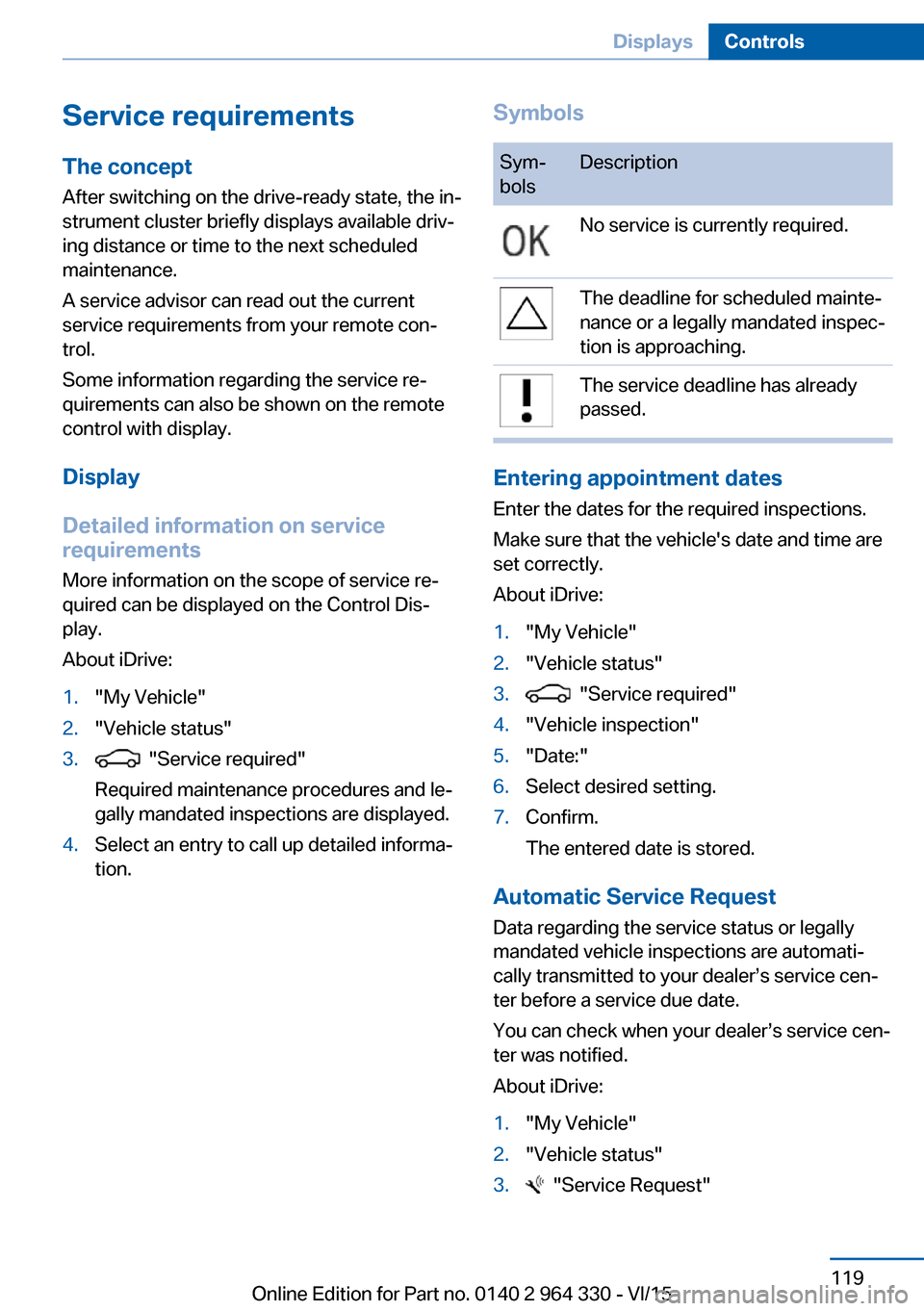
tion.SymbolsSym‐
bolsDescriptionNo service is currently required.The deadline for scheduled mainte‐
nance or a legally mandated inspec‐
tion is approaching.The service deadline has already
passed.
Entering appointment dates
Enter the dates for the required inspections.
Make sure that the vehicle's date and time are
set correctly.
About iDrive:
1."My Vehicle"2."Vehicle status"3. "Service required"4."Vehicle inspection"5."Date:"6.Select desired setting.7.Confirm.
The entered date is stored.
Automatic Service Request
Data regarding the service status or legally
mandated vehicle inspections are automati‐
cally transmitted to your dealer’s service cen‐
ter before a service due date.
You can check when your dealer’s service cen‐
ter was notified.
About iDrive:
1."My Vehicle"2."Vehicle status"3. "Service Request"Seite 119DisplaysControls119
Online Edition for Part no. 0140 2 964 330 - VI/15
Page 126 of 314
Activating/deactivating the speed
warning
About iDrive:1."My Vehicle"2."Vehicle settings"3."Speed warning"4."Speed warning"5.Press the controller.
Setting your current speed as the
speed warning
About iDrive:
1."My Vehicle"2."Vehicle settings"3."Speed warning"4."Select current speed"5.Press the controller.
The current vehicle speed is stored as the
speed warning.
Vehicle status
The concept The status can be displayed and actions per‐
formed for several systems.
Opening the vehicle status
About iDrive:
1."My Vehicle"2."Vehicle status"
Information at a glance
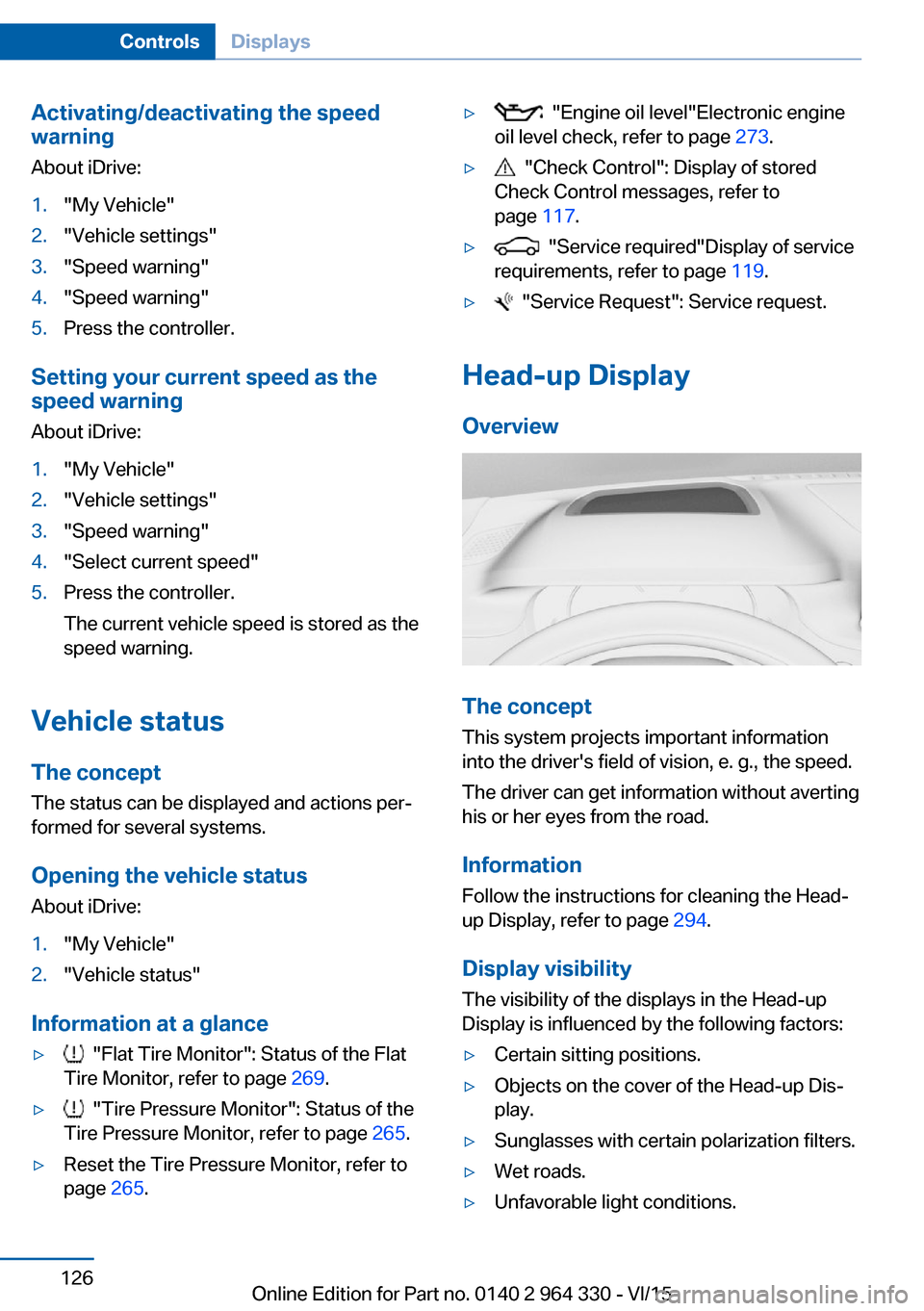
▷ "Flat Tire Monitor": Status of the Flat
Tire Monitor, refer to page 269.▷ "Tire Pressure Monitor": Status of the
Tire Pressure Monitor, refer to page 265.▷Reset the Tire Pressure Monitor, refer to
page 265.▷ "Engine oil level"Electronic engine
oil level check, refer to page 273.▷ "Check Control": Display of stored
Check Control messages, refer to
page 117.▷ "Service required"Display of service
requirements, refer to page 119.▷ "Service Request": Service request.
Head-up Display
Overview
The concept
This system projects important information
into the driver's field of vision, e. g., the speed.
The driver can get information without averting
his or her eyes from the road.
Information Follow the instructions for cleaning the Head-
up Display, refer to page 294.
Display visibility The visibility of the displays in the Head-up
Display is influenced by the following factors:
▷Certain sitting positions.▷Objects on the cover of the Head-up Dis‐
play.▷Sunglasses with certain polarization filters.▷Wet roads.▷Unfavorable light conditions.Seite 126ControlsDisplays126
Online Edition for Part no. 0140 2 964 330 - VI/15
Page 127 of 314
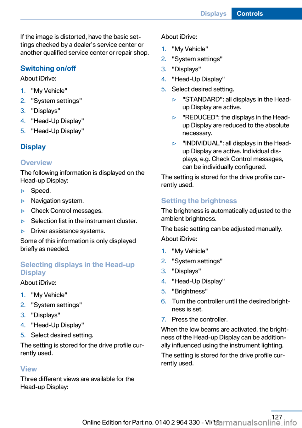
If the image is distorted, have the basic set‐
tings checked by a dealer’s service center or
another qualified service center or repair shop.
Switching on/off
About iDrive:1."My Vehicle"2."System settings"3."Displays"4."Head-Up Display"5."Head-Up Display"
Display
Overview
The following information is displayed on the
Head-up Display:
▷Speed.▷Navigation system.▷Check Control messages.▷Selection list in the instrument cluster.▷Driver assistance systems.
Some of this information is only displayed
briefly as needed.
Selecting displays in the Head-up
Display
About iDrive:
1."My Vehicle"2."System settings"3."Displays"4."Head-Up Display"5.Select desired setting.
The setting is stored for the drive profile cur‐
rently used.
View Three different views are available for the
Head-up Display:
About iDrive:1."My Vehicle"2."System settings"3."Displays"4."Head-Up Display"5.Select desired setting.▷"STANDARD": all displays in the Head-
up Display are active.▷"REDUCED": the displays in the Head- up Display are reduced to the absolute
necessary.▷"INDIVIDUAL": all displays in the Head-
up Display are active. Individual dis‐
plays, e.g. Check Control messages,
can be individually configured.
The setting is stored for the drive profile cur‐
rently used.
Setting the brightness The brightness is automatically adjusted to the
ambient brightness.
The basic setting can be adjusted manually.
About iDrive:
1."My Vehicle"2."System settings"3."Displays"4."Head-Up Display"5."Brightness"6.Turn the controller until the desired bright‐
ness is set.7.Press the controller.
When the low beams are activated, the bright‐
ness of the Head-up Display can be addition‐
ally influenced using the instrument lighting.
The setting is stored for the drive profile cur‐
rently used.
Seite 127DisplaysControls127
Online Edition for Part no. 0140 2 964 330 - VI/15
Page 128 of 314
Adjusting the height
About iDrive:1."My Vehicle"2."System settings"3."Displays"4."Head-Up Display"5."Height"6.Turn the controller until the desired height
is reached.7.Press the controller.
The setting is stored for the drive profile cur‐
rently used.
Setting the rotation The screen of the Head-up Display can be ro‐
tated around its own axis.
About iDrive:
1."My Vehicle"2."System settings"3."Displays"4."Head-Up Display"5."Rotation"6.Turn the controller until the desired setting
is selected.7.Press the controller.
The setting is stored for the drive profile cur‐
rently used.
Special windshield The windshield is part of the system.
The shape of the windshield makes it possible
to display a precise image.
A film in the windshield prevents double im‐
ages from being displayed.
For this reason, it is strongly suggested to
have the special windshield replaced by a
dealer’s service center or another qualified
service center or repair shop.
Seite 128ControlsDisplays128
Online Edition for Part no. 0140 2 964 330 - VI/15
Page 138 of 314
spective accident severity. There is risk of
injuries or danger to life. Have the airbag sys‐
tem checked, repaired, dismantled and scrap‐
ped by a dealer’s service center or another
qualified service center or repair shop.◀
Correct function When drive readiness is switched on,
the warning lamp in the instrument
cluster lights up briefly and thereby in‐
dicates the function readiness of the entire air‐
bag system and the belt tensioners.
Airbag system malfunctioning▷Warning lamp does not come on when
drive readiness is switched on.▷The warning lamp lights up continuously.
Automatic deactivation of the front-
seat passenger airbags
The concept The system reads if the front passenger seat is
occupied by measuring the human body's re‐
sistance.
Front, knee and side airbag on the front pas‐
senger's side are either activated or deacti‐
vated.
Information Before transporting a child on the front pas‐
senger seat, refer to the safety notes and in‐
structions for children on the front passenger
seat, see Children.
WARNING
The ensure the front-seat passenger air‐
bag function, it must be detected, whether a
person occupies the front passenger seat. The
entire seat cushion area must be used for this
purpose. There is risk of injuries or danger to
life. Make sure that the front passenger keeps
his or her feet in the floor area.◀
Malfunction of the automatic
deactivation system
When transporting older children and adults,
the front-seat passenger airbags may be deac‐
tivated in certain sitting positions. In this case,
the indicator lamp for the front-seat passenger
airbags lights up.
In this case, change the sitting position so that
the front-seat passenger airbags are activated
and the indicator lamp goes out.
If it is not possible to activate the airbags, have
the person sit in the rear.
To enable correct recognition of the occupied
seat cushion▷Do not attach covers, cushions, ball mats
or other items to the front passenger seat
unless they are specifically determined to
be safe for use on the front passenger
seat.▷Do not place any electronic devices on the
passenger seat if a child restraint system is
to be installed on it.▷Do not place objects under the seat that
could press against the seat from below.▷No moisture in or on the seat.
Indicator lamp for the front-seat
passenger airbags
The indicator lamp for the front-seat passen‐
ger airbag in the roofliner indicates the operat‐
ing state of the front-seat passenger airbag.
The lamp indicates whether the airbags are ei‐
ther activated or deactivated.
After drive readiness is switched on, the lamp
briefly lights up and then indicates whether the
airbags are either activated or deactivated.
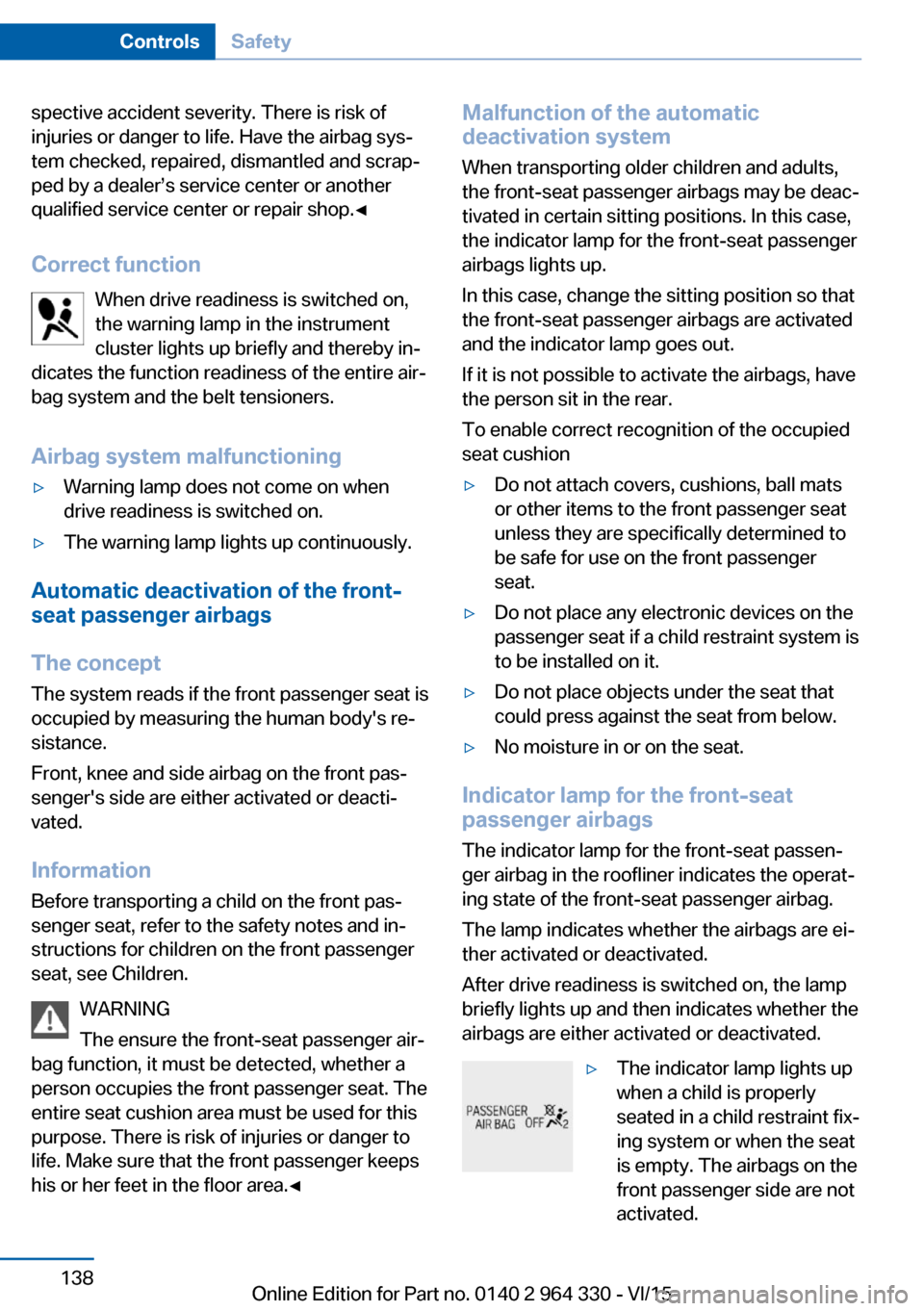
▷The indicator lamp lights up
when a child is properly
seated in a child restraint fix‐
ing system or when the seat
is empty. The airbags on the
front passenger side are not
activated.Seite 138ControlsSafety138
Online Edition for Part no. 0140 2 964 330 - VI/15
Page 201 of 314
Press button and hold for approx. 7 sec‐
onds, then release. The LED flashes fast.
Activate system:
The system is activated again automatically
when you drive away.
Malfunction
A Check Control message is displayed. The
system is disrupted. Vehicle handling may be
altered and driving comfort may be noticeably
reduced. Have checked by a dealer’s service
center or another qualified service center or re‐
pair shop.
Long periods when vehicle is parked During long periods when the vehicle is
parked, it can lower itself. This is not a mal‐
function.
Dynamic Damping Control The conceptThis system reduces undesirable vehicle mo‐tion when using a dynamic driving style or trav‐
eling on uneven road surfaces.
The system enhances driving dynamics and
comfort fitting road surface and driving style.
General information
The system offers several different damping
settings.
These are assigned to the different driving
modes of the Driving Dynamics Control, refer
to page 110.TuningDrive modeDamper tuningCOMFORT PLUScomfortableSPORTfirmCOMFORT/ECO PRObalanced out
Executive Drive Pro
The concept Executive Drive Pro is an actively controlled
chassis. It increases driving comfort and mini‐
mizes the lateral tilt when driving around
curves. This increases both the agility of the
vehicle as well as the vehicle comfort.
Executive Drive Pro includes the following sys‐
tems:
▷Active damping adjustment, refer to
page 201.▷Active roll stabilization, refer to page 202.
Active damping adjustment
The concept The system increases driving comfort. Using a
camera in the area of the interior mirror, the
road surface is detected and damping auto‐
matically adjusted to the road surface.
Seite 201Driving comfortControls201
Online Edition for Part no. 0140 2 964 330 - VI/15
Page 202 of 314
Overview
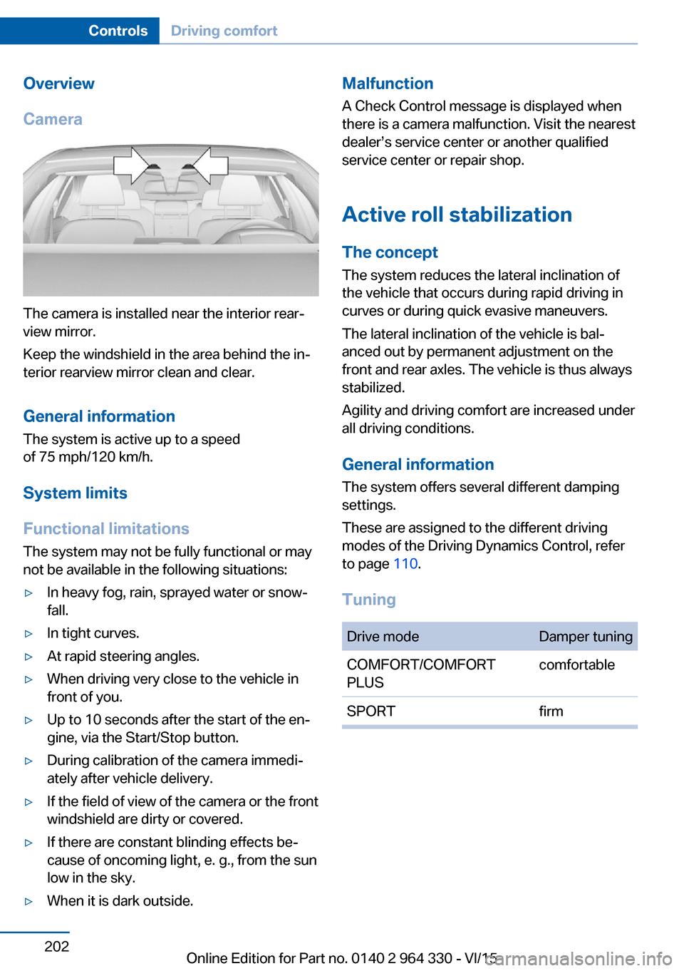
Camera
The camera is installed near the interior rear‐
view mirror.
Keep the windshield in the area behind the in‐
terior rearview mirror clean and clear.
General information
The system is active up to a speed
of 75 mph/120 km/h.
System limits
Functional limitations The system may not be fully functional or may
not be available in the following situations:
▷In heavy fog, rain, sprayed water or snow‐
fall.▷In tight curves.▷At rapid steering angles.▷When driving very close to the vehicle in
front of you.▷Up to 10 seconds after the start of the en‐
gine, via the Start/Stop button.▷During calibration of the camera immedi‐
ately after vehicle delivery.▷If the field of view of the camera or the front
windshield are dirty or covered.▷If there are constant blinding effects be‐
cause of oncoming light, e. g., from the sun
low in the sky.▷When it is dark outside.Malfunction
A Check Control message is displayed when
there is a camera malfunction. Visit the nearest
dealer’s service center or another qualified
service center or repair shop.
Active roll stabilization
The concept The system reduces the lateral inclination of
the vehicle that occurs during rapid driving in
curves or during quick evasive maneuvers.
The lateral inclination of the vehicle is bal‐
anced out by permanent adjustment on the
front and rear axles. The vehicle is thus always
stabilized.
Agility and driving comfort are increased under
all driving conditions.
General information
The system offers several different damping
settings.
These are assigned to the different driving
modes of the Driving Dynamics Control, refer
to page 110.
TuningDrive modeDamper tuningCOMFORT/COMFORT
PLUScomfortableSPORTfirmSeite 202ControlsDriving comfort202
Online Edition for Part no. 0140 2 964 330 - VI/15
Page 214 of 314
Make sure that no objects press against
the cartridge holder from below, otherwise
the function of the ambient air package
could be impacted.6.Close the glove compartment.
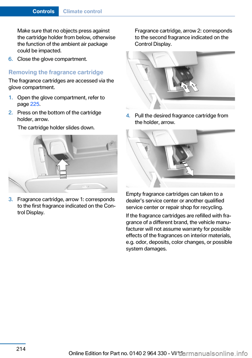
Removing the fragrance cartridge
The fragrance cartridges are accessed via the
glove compartment.
1.Open the glove compartment, refer to
page 225.2.Press on the bottom of the cartridge
holder, arrow.
The cartridge holder slides down.3.Fragrance cartridge, arrow 1: corresponds
to the first fragrance indicated on the Con‐
trol Display.Fragrance cartridge, arrow 2: corresponds
to the second fragrance indicated on the
Control Display.4.Pull the desired fragrance cartridge from
the holder, arrow.
Empty fragrance cartridges can taken to a
dealer’s service center or another qualified
service center or repair shop for recycling.
If the fragrance cartridges are refilled with fra‐
grance of a different brand, the vehicle manu‐
facturer will not assume warranty for possible
effects of the fragrances on interior materials,
e.g. odor, deposits, color changes, or possible
system damages.
Seite 214ControlsClimate control214
Online Edition for Part no. 0140 2 964 330 - VI/15
Page 215 of 314
Interior equipmentVehicle features and optionsThis chapter describes all standard, country-
specific and optional features offered with the
series. It also describes features that are not
necessarily available in your car, e. g., due to
the selected options or country versions. This
also applies to safety-related functions and
systems. The respectively applicable country
provisions must be observed when using the
respective features and systems.
Universal Integrated Remote Control
The concept The universal garage door opener can operate
up to 3 functions of remote-controlled sys‐
tems such as garage door drives or lighting
systems. The universal garage door opener re‐
places up to 3 different hand-held transmitters.
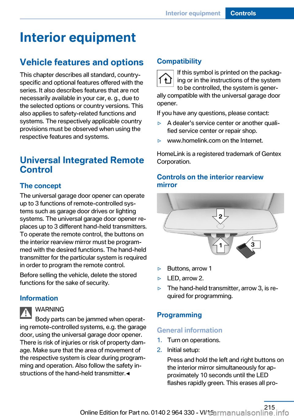
To operate the remote control, the buttons on
the interior rearview mirror must be program‐
med with the desired functions. The hand-held
transmitter for the particular system is required
in order to program the remote control.
Before selling the vehicle, delete the stored
functions for the sake of security.
Information WARNING
Body parts can be jammed when operat‐
ing remote-controlled systems, e.g. the garage
door, using the universal garage door opener.
There is risk of injuries or risk of property dam‐
age. Make sure that the area of movement of
the respective system is clear during program‐
ming and operation. Also follow the safety in‐
structions of the hand-held transmitter.◀Compatibility
If this symbol is printed on the packag‐
ing or in the instructions of the system
to be controlled, the system is gener‐
ally compatible with the universal garage door opener.
If you have any questions, please contact:▷A dealer’s service center or another quali‐
fied service center or repair shop.▷www.homelink.com on the Internet.
HomeLink is a registered trademark of Gentex
Corporation.
Controls on the interior rearview
mirror
▷Buttons, arrow 1▷LED, arrow 2.▷The hand-held transmitter, arrow 3, is re‐
quired for programming.
Programming
General information
1.Turn on operations.2.Initial setup:
Press and hold the left and right buttons on
the interior mirror simultaneously for ap‐
proximately 10 seconds until the LED
flashes rapidly green. This erases all pro‐Seite 215Interior equipmentControls215
Online Edition for Part no. 0140 2 964 330 - VI/15
Page 224 of 314
Switching onThe cooler can be operated at two levels.1.Turn on operations.2. Press button once for each cooling
level.
The highest cooling power is active when
two LEDs are lit.
If the cooler was switched on the last time op‐
erating readiness was switched off, it will like‐
wise be switched on the next time operating
readiness is switched on.
Switch off Press button repeatedly until the LEDs go out.
Removing
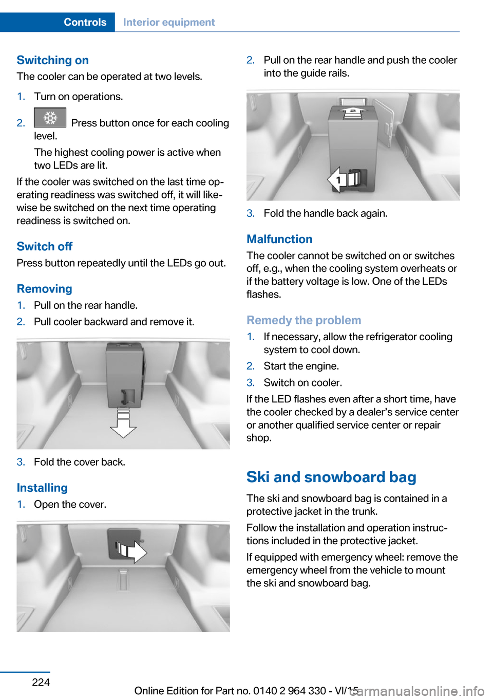
1.Pull on the rear handle.2.Pull cooler backward and remove it.3.Fold the cover back.
Installing
1.Open the cover.2.Pull on the rear handle and push the cooler
into the guide rails.3.Fold the handle back again.
Malfunction
The cooler cannot be switched on or switches
off, e.g., when the cooling system overheats or
if the battery voltage is low. One of the LEDs
flashes.
Remedy the problem
1.If necessary, allow the refrigerator cooling
system to cool down.2.Start the engine.3.Switch on cooler.
If the LED flashes even after a short time, have
the cooler checked by a dealer’s service center
or another qualified service center or repair
shop.
Ski and snowboard bag The ski and snowboard bag is contained in a
protective jacket in the trunk.
Follow the installation and operation instruc‐
tions included in the protective jacket.
If equipped with emergency wheel: remove the
emergency wheel from the vehicle to mount
the ski and snowboard bag.
Seite 224ControlsInterior equipment224
Online Edition for Part no. 0140 2 964 330 - VI/15