ECO mode BMW 7 SERIES LONG 2004 E66 MOST Bus Diagnosis Workshop Manual
[x] Cancel search | Manufacturer: BMW, Model Year: 2004, Model line: 7 SERIES LONG, Model: BMW 7 SERIES LONG 2004 E66Pages: 20, PDF Size: 0.13 MB
Page 3 of 20

3
MOST Bus Diagnosis
System Overview
MOST Technology
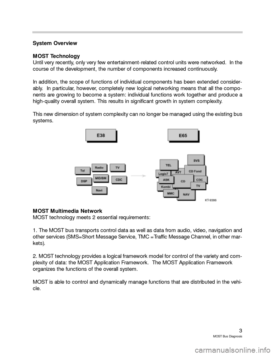
Until very recently, only very few entertainment-related control units were networked. In the
course of the development, the number of components increased continuously.
In addition, the scope of functions of individual components has been extended consider-
ably. In particular, however, completely new logical networking means that all the compo-
nents are growing to become a system: individual functions work together and produce a
high-quality overall system. This results in significant growth in system complexity.
This new dimension of system complexity can no longer be managed using the existing bus
systems.
MOST Multimedia Network
MOST technology meets 2 essential requirements:
1. The MOST bus transports control data as well as data from audio, video, navigation and
other services (SMS=Short Message Service, TMC =Traffic Message Channel, in other mar-
kets).
2. MOST technology provides a logical framework model for control of the variety and com-
plexity of data: the MOST Application Framework. The MOST Application Framework
organizes the functions of the overall system.
MOST is able to control and dynamically manage functions that are distributed in the vehi-
cle.
KT-9386
Page 16 of 20

16
MOST Bus Diagnosis
Ring Break Test
If there is a break in the ring (a defect between two control modules) the following fault pat-
terns may occur:
Transmit diode of the transmitting control module defective
Power supply of the transmitting control module defective
Internal control module fault of the transmitting control module
Receiver diode of the receiving control module defective
Power supply of the receiving control module defective
Internal control module fault of the receiving control module
Optical wave guide between transmitting and receiving control module defective
These faults may occur alone or in combination. To diagnose a ring break, the first step is
to locate the two control modules between which the transmission failure has occurred.
This is accomplished with the ring break diagnostic function. Once the two control modules
have been identified and the diagnostics have been performed, remember to check the
power supply and ground circuit of both modules before condemning a module.
Testing of the transmit/receive diodes will be possible using the OPPS tester.
Perform Ring Break Test
The ring break test mode is entered automatically when the power to all the modules in the
MOST network is switched off and then switched back on. The most effective method of
switching the power off and on is to disconnect the battery negative terminal for 45 sec-
onds. This time will allow the capacitors of all the control modules to dissipate.
When the battery is reconnected the control modules wake up and in MOST network order
transmit a light signal to the next module. Each module checks to see if it has received a
light signal from the previous module. If the control module does NOT receive a light input
signal it still transmits a signal to the next module. A relative node number of 0 is stored in
the control module that did not receive a signal but that transmitted one.
The Control Display receives the light signal back and identifies which modules responded.
Go to “Control Unit Functions” Control Display Gateway and read fault memory.