length BMW 740IL 1994 E38 Central Body Electronics ZKE Manual
[x] Cancel search | Manufacturer: BMW, Model Year: 1994, Model line: 740IL, Model: BMW 740IL 1994 E38Pages: 80, PDF Size: 4.14 MB
Page 15 of 80

• If the ignition switch is turned off with the wiper switch in the intermittent position, the rain
sensor will only become active after the ignition is switched back on and one of the fol-
lowing occurs:
- The stalk switch is moved from the intermittent position and then back.
- The knurled wheel setting is adjusted.
- or the wash function is activated.
The reasoning behind this switching strategy is to have the driver make a conscious deci-
sion to activate the system themselves.
Rain Sensor Control Module Adaptation
The rain sensor control module adapts to the optics system environment as follows:
Windshield Aging:As the vehicle ages the possibility of stone chipping in the rain sensors
monitoring area may occur which will cause a loss of light in the optics system.
The control module adapts for loss of light based on the intensity of the detected infra red
light with a cleared windshield (wiper motor park signal). Therefore, the rain sensors func-
tion is not adversely affected due to windshield aging.
Dirty Windows:The rain sensor adaptation reacts less sensitively to a dirty windshield
(dirt, road salt, wax residue) after a completed wipe cycle. A dirty windshield has a film on
it that diminishes the ability of the infra red to refract into present water droplets. This caus-
es a delay in the rain sensor detection capabilities which lengthens the time intervals on an
intermittent wipe.
Windshield Wiper System Failsafe Operation
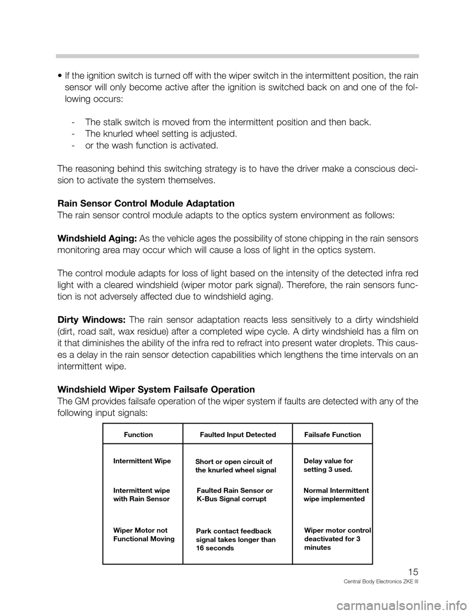
The GM provides failsafe operation of the wiper system if faults are detected with any of the
following input signals:
15
Central Body Electronics ZKE III
Function Faulted Input Detected Failsafe Function
Intermittent Wipe
Short or open circuit of
the knurled wheel signalDelay value for
setting 3 used.
Intermittent wipe
with Rain SensorFaulted Rain Sensor or
K-Bus Signal corruptNormal Intermittent
wipe implemented
Wiper Motor not
Functional MovingPark contact feedback
signal takes longer than
16 secondsWiper motor control
deactivated for 3
minutes
Page 70 of 80

Steering Column
Principle of Operation
The electrically adjustable steering column used in the various
models (if equipped) is similar in components, mechanical link-
ages and electrical operation.
The steering column adjusting switch is mounted on the left
side of the steering column and provides for four directions of
column movement. The steering column switch inputs are
processed by the seat module.
Motor Drives:
Forward/Back (Telescope)
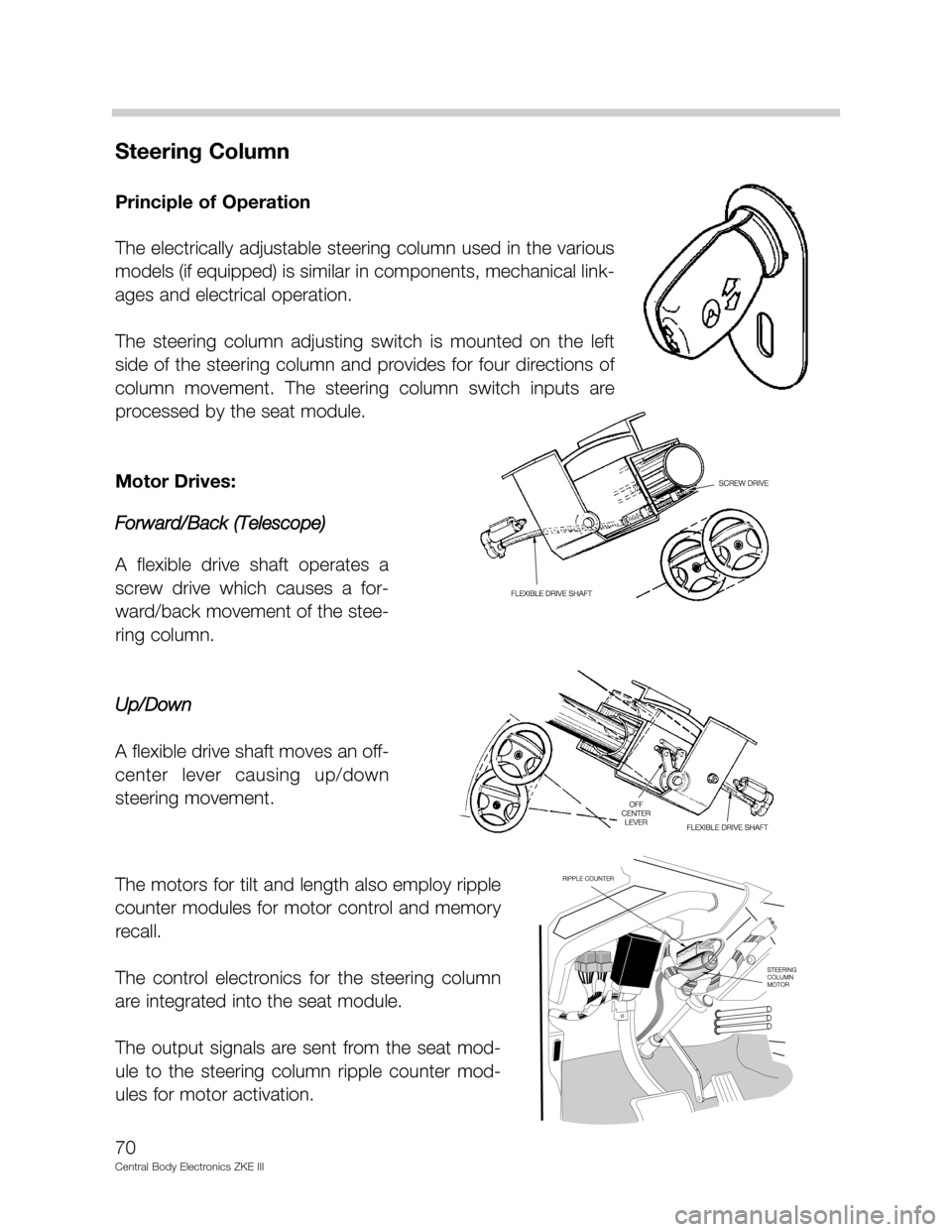
A flexible drive shaft operates a
screw drive which causes a for-
ward/back movement of the stee-
ring column.
Up/Down
A flexible drive shaft moves an off-
center lever causing up/down
steering movement.
The motors for tilt and length also employ ripple
counter modules for motor control and memory
recall.
The control electronics for the steering column
are integrated into the seat module.
The output signals are sent from the seat mod-
ule to the steering column ripple counter mod-
ules for motor activation.
70
Central Body Electronics ZKE III