rear entertainment BMW 740LI SEDAN 2012 User Guide
[x] Cancel search | Manufacturer: BMW, Model Year: 2012, Model line: 740LI SEDAN, Model: BMW 740LI SEDAN 2012Pages: 299, PDF Size: 8.49 MB
Page 63 of 299
Mounting LATCH child restraint fixing
systems on power rear seats
*
1. Before mounting, adjust the seats to their
basic position, refer to page 52.
2. For better accessibility, tilt the backrest
back slightly.
3. Mount the child restraint fixing system; refer
to the operating instructions of the system.
4. Ensure that both LATCH anchors are prop‐
erly connected.
5. After mounting, move the backrest back up
slightly so that the child restraint fixing sys‐
tem rests lightly against the backrest.
Child restraint fixing system with a
tether strap LATCH mounting eyes
Only
use the mounting eyes for the upper
LATCH retaining strap to secure child restraint
fixing systems; otherwise, the mounting eyes
could be damaged.◀
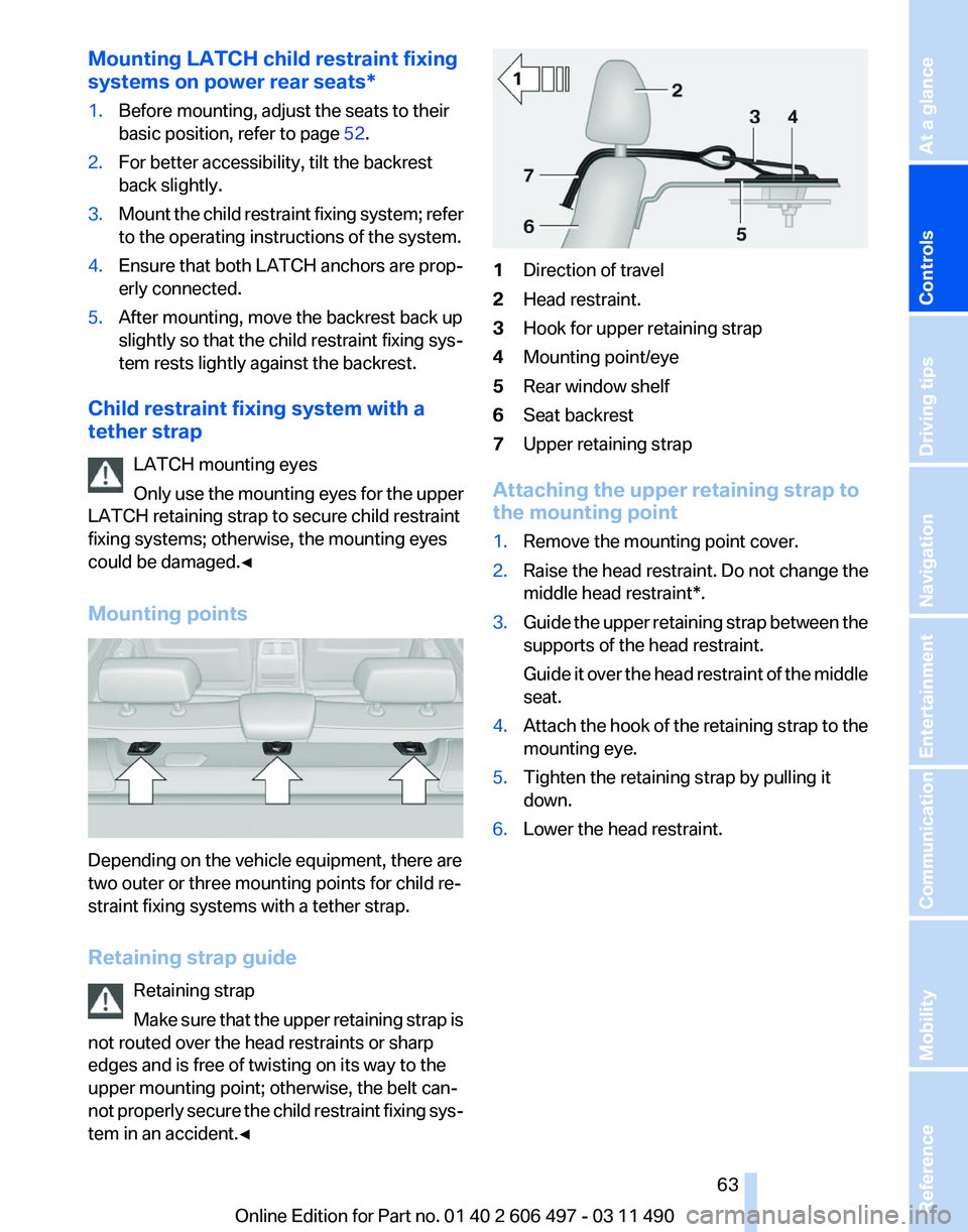
Mounting points Depending on the vehicle equipment, there are
two outer or three mounting points for child re‐
straint fixing systems with a tether strap.
Retaining strap guide
Retaining strap
Make
sure that the upper retaining strap is
not routed over the head restraints or sharp
edges and is free of twisting on its way to the
upper mounting point; otherwise, the belt can‐
not properly secure the child restraint fixing sys‐
tem in an accident.◀ 1
Direction of travel
2 Head restraint.
3 Hook for upper retaining strap
4 Mounting point/eye
5 Rear window shelf
6 Seat backrest
7 Upper retaining strap
Attaching the upper retaining strap to
the mounting point
1. Remove the mounting point cover.
2. Raise the head restraint. Do not change the
middle head restraint*.
3. Guide the upper retaining strap between the
supports of the head restraint.
Guide
it over the head restraint of the middle
seat.
4. Attach the hook of the retaining strap to the
mounting eye.
5. Tighten the retaining strap by pulling it
down.
6. Lower the head restraint.
Seite 63
63Online Edition for Part no. 01 40 2 606 497 - 03 11 490
Reference Mobility Communication Entertainment Navigation Driving tips
Controls At a glance
Page 71 of 299
Switching off and brief wipe
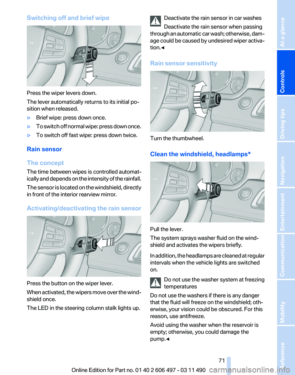
Press the wiper levers down.
The lever automatically returns to its initial po‐
sition when released.
▷
Brief wipe: press down once.
▷ To switch off normal wipe: press down once.
▷ To switch off fast wipe: press down twice.
Rain sensor
The concept
The time between wipes is controlled automat‐
ically
and depends on the intensity of the rainfall.
The sensor is located on the windshield, directly
in front of the interior rearview mirror.
Activating/deactivating the rain sensor Press the button on the wiper lever.
When
activated, the wipers move over the wind‐
shield once.
The LED in the steering column stalk lights up. Deactivate the rain sensor in car washes
Deactivate the rain sensor when passing
through
an automatic car wash; otherwise, dam‐
age could be caused by undesired wiper activa‐
tion.◀
Rain sensor sensitivity Turn the thumbwheel.
Clean the windshield,
headlamps* Pull the lever.
The system sprays washer fluid on the wind‐
shield and activates the wipers briefly.
In
addition, the headlamps are cleaned at regular
intervals when the vehicle lights are switched
on.
Do not use the washer system at freezing
temperatures
Do not use the washers if there is any danger
that the fluid will freeze on the windshield; oth‐
erwise, your vision could be obscured. For this
reason, use antifreeze.
Avoid using the washer when the reservoir is
empty; otherwise, you could damage the
pump.◀ Seite 71
71Online Edition for Part no. 01 40 2 606 497 - 03 11 490
Reference Mobility Communication Entertainment Navigation Driving tips
Controls At a glance
Page 87 of 299
▷
In poorly-lit towns and cities and in the pres‐
ence of highly reflective signs.
▷ At low speeds.
▷ When the windshield in front of the interior
rearview mirror is fogged over, dirty or cov‐
ered with stickers, etc.
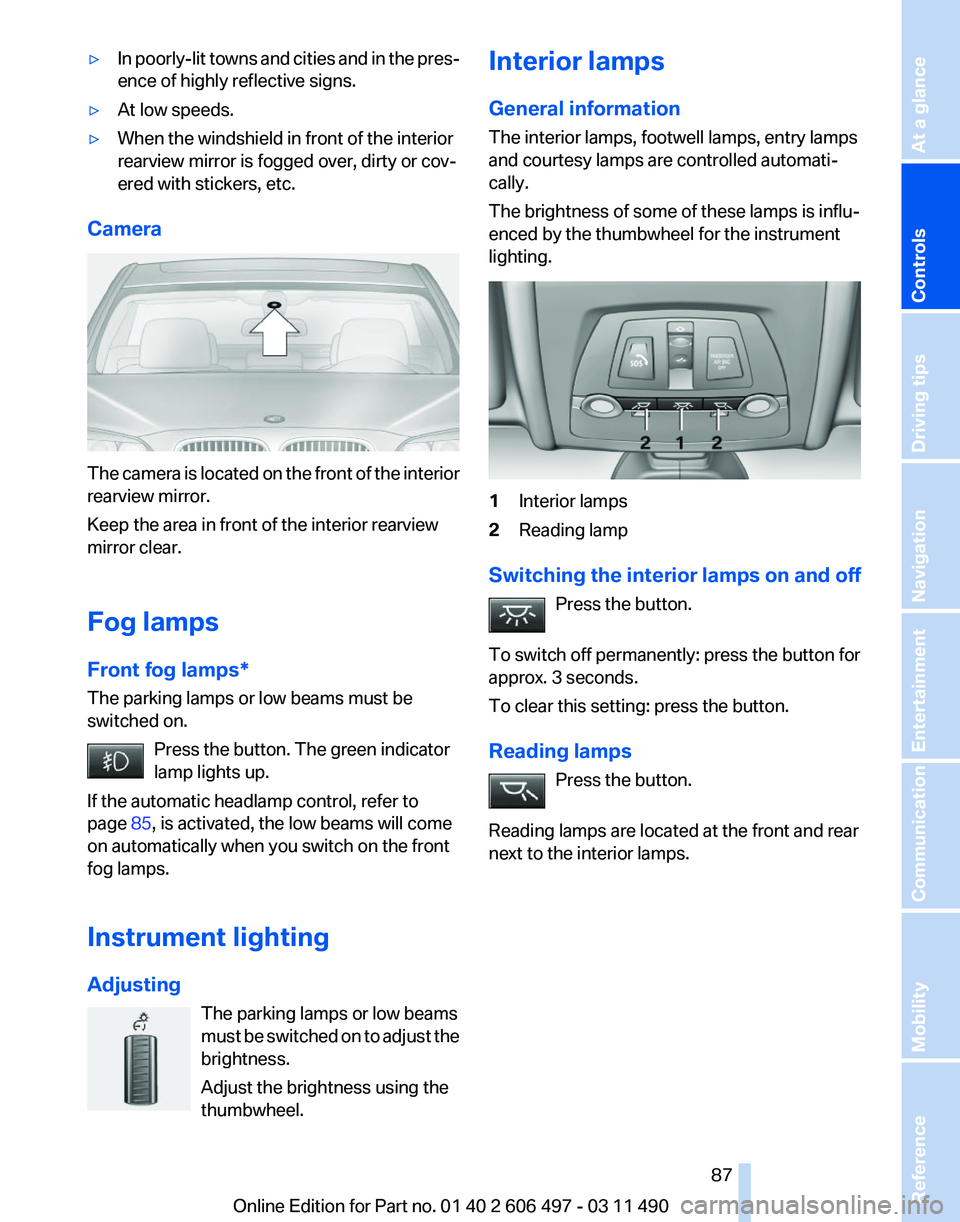
Camera The camera is located on the front of the interior
rearview mirror.
Keep the area in front of the interior rearview
mirror clear.
Fog lamps
Front fog lamps*
The parking lamps or low beams must be
switched on.
Press the button. The green indicator
lamp lights up.
If the automatic headlamp control, refer to
page 85, is activated, the low beams will come
on automatically when you switch on the front
fog lamps.
Instrument lighting
Adjusting
The parking lamps or low beams
must
be switched on to adjust the
brightness.
Adjust the brightness using the
thumbwheel. Interior lamps
General information
The interior lamps, footwell lamps, entry lamps
and courtesy lamps are controlled automati‐
cally.
The brightness of some of these lamps is influ‐
enced by the thumbwheel for the instrument
lighting.
1
Interior lamps
2 Reading lamp
Switching the interior lamps on and off Press the button.
To switch off permanently: press the button for
approx. 3 seconds.
To clear this setting: press the button.
Reading lamps Press the button.
Reading lamps are located at the front and rear
next to the interior lamps. Seite 87
87Online Edition for Part no. 01 40 2 606 497 - 03 11 490
Reference Mobility Communication Entertainment Navigation Driving tips
Controls At a glance
Page 95 of 299
▷
When braking hard.
▷ When using the turn signal.
System limits Personal responsibility
The system cannot serve as a substitute
for
the driver's personal judgment of the course
of the road and the traffic situation.
In the event of a warning, do not jerk the steering
wheel, as you may lose control of the vehicle.◀
The system may not be fully functional in the
following situations:
▷ In heavy fog, rain or snowfall.
▷ In the event of worn, poorly visible, merging,
diverging,
or multiple lane markings such as
in construction areas.
▷ When lane markings are covered in snow,
ice, dirt or water.
▷ In tight curves or on narrow lanes.
▷ When the lane markings are covered by ob‐
jects.
▷ When driving very close to the vehicle in
front of you.
▷ When driving toward bright lights.
▷ When the windshield in front of the interior
rearview mirror is fogged over, dirty or cov‐
ered with stickers, etc.
Malfunctions
Steering wheel vibration
Frequent
activation of the steering wheel vibra‐
tion causes the system to overheat.
This causes the lane departure warning to be‐
come deactivated.
Let the system cool and reactivate it by pressing
the button. Camera
The camera is located on the front of the interior
rearview mirror.
Keep the area in front of the interior rearview
mirror clear.
Active Blind Spot Detection
*
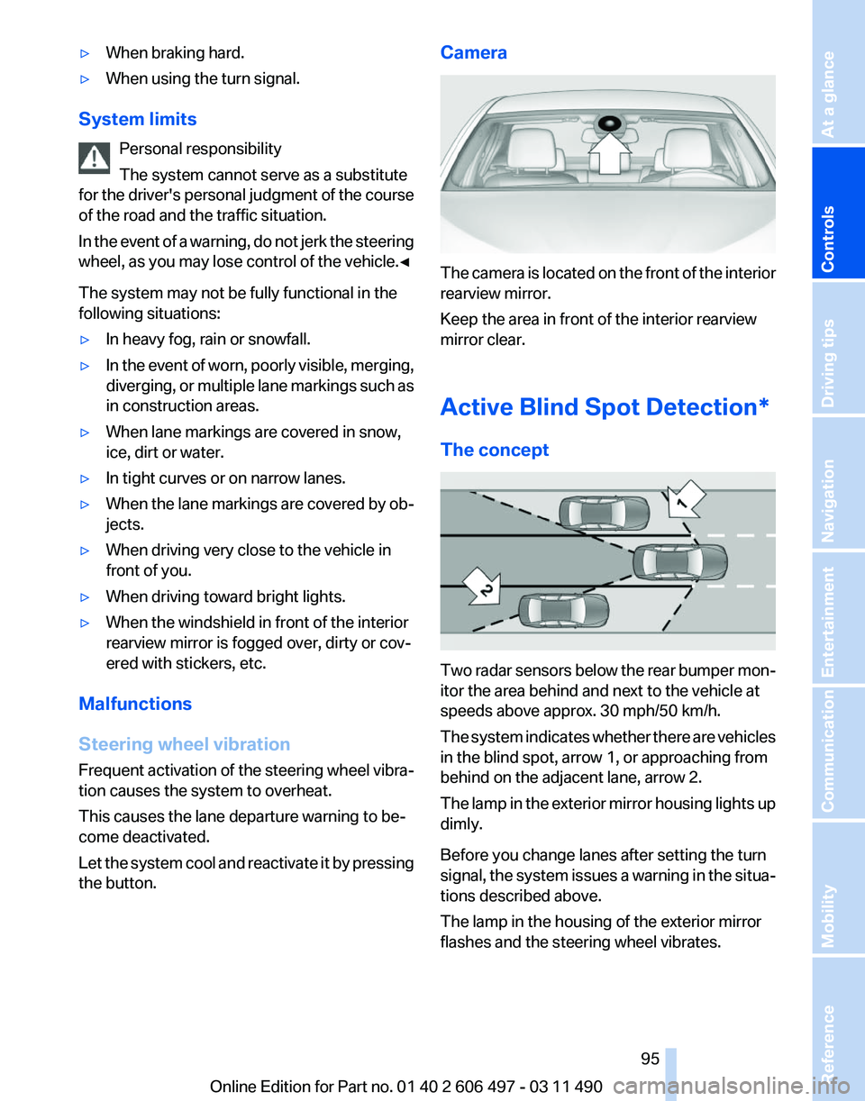
The concept Two radar sensors below the rear bumper mon‐
itor the area behind and next to the vehicle at
speeds above approx. 30 mph/50 km/h.
The
system indicates whether there are vehicles
in the blind spot, arrow 1, or approaching from
behind on the adjacent lane, arrow 2.
The lamp in the exterior mirror housing lights up
dimly.
Before you change lanes after setting the turn
signal, the system issues a warning in the situa‐
tions described above.
The lamp in the housing of the exterior mirror
flashes and the steering wheel vibrates.
Seite 95
95Online Edition for Part no. 01 40 2 606 497 - 03 11 490
Reference Mobility Communication Entertainment Navigation Driving tips
Controls At a glance
Page 99 of 299
DTC Dynamic Traction
Control
The concept
The
DTC system is a version of the DSC in which
forward momentum is optimized.
The system ensures maximum forward momen‐
tum on special road conditions, e.g., unplowed
snowy roads, but driving stability is limited.
It is therefore necessary to drive with appropri‐
ate caution.
You may find it useful to briefly activate DTC un‐
der the following special circumstances:
▷ When driving in slush or on uncleared,
snow-covered roads.
▷ When rocking the vehicle or driving off in
deep snow or on loose surfaces.
▷ When driving with snow chains.
Deactivating/activating DTC Dynamic
Traction Control
The
system can be deactivated/activated via the
TRACTION and SPORT+ programs of the Dy‐
namic Driving Control, refer to page 102.
xDrive*
xDrive is the all-wheel-drive system of your ve‐
hicle. Concerted action by the xDrive and DSC
further optimize traction and driving dynamics.
The xDrive all-wheel-drive system variably dis‐
tributes the drive forces to the front and rear
axles as demanded by the driving situation and
road surface.
HDC Hill Descent Control*
The concept
HDC is a downhill driving assistant that auto‐
matically controls vehicle speed on steep down‐
hill gradients. Without requiring brake applica‐
tion, the vehicle moves at slightly more than
twice walking speed. You can activate the Hill Descent Control at
speeds below approx. 22 mph/35 km/h. When
driving downhill, the vehicle reduces its speed
to approx. twice walking speed and then keeps
its speed constant.
While you are actively braking, the system is on
standby.
The system does not brake the vehicle
during this time.
Increasing or decreasing vehicle speed
You can specify your desired speed in the range
from approx. 4 mph/6 km/h to approx. 15 mph/
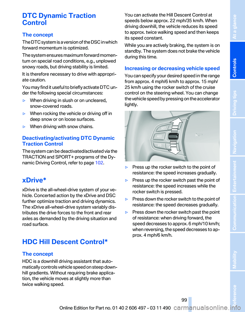
25 km/h using the rocker switch of the cruise
control on the steering wheel. You can change
the vehicle speed by pressing on the accelerator
lightly. ▷
Press up the rocker switch to the point of
resistance: the speed increases gradually.
▷ Press up the rocker switch past the point of
resistance: the speed increases while the
rocker switch is pressed.
▷ Press down the rocker switch to the point of
resistance: the speed decreases gradually.
▷ Press down the rocker switch past the point
of resistance: when driving forward, the
speed
decreases to approx. 6 mph/10 km/h;
when reversing, the speed decreases to ap‐
prox. 4 mph/6 km/h.
Seite 99
99Online Edition for Part no. 01 40 2 606 497 - 03 11 490
Reference Mobility Communication Entertainment Navigation Driving tips
Controls At a glance
Page 101 of 299
NORMAL
Balanced tuning between the COMFORT and
SPORT programs.
COMFORT
Comfort-oriented
tuning of the shock absorbers
for optimal traveling comfort.
Integral Active Steering*
The concept
Integral Active Steering is a combination of Ac‐
tive Steering and rear axle steering.
Active Steering varies the steering angle of the
wheels in relation to the steering wheel move‐
ment as a function of the speed.
At speeds up to approx. 37 mph/60 km/h, e.g.,
in curves, the steering angle is increased, i.e.,
steering becomes more direct.
The rear axle steering acts to increase maneu‐
verability by turning the rear wheels slightly in a
direction opposite to the front wheels.
At higher speeds, the steering angle is increas‐
ingly reduced.
The rear wheels are turned to the same angle as
the front wheels.
In critical situations, Integral Active Steering can
specifically steer the front and rear wheels to
stabilize the vehicle before the driver intervenes,
e.g., when braking where road conditions differ
on the left and right sides of the vehicle.
Initializing
In rare cases, it may become necessary to initi‐
alize the Integral Active Steering.
The warning lamp lights up. A Check
Control message is displayed.
1. With the engine running, turn the steering
wheel
all the way to the left and right several
times in a uniform manner until the warning
lamp disappears.
2. Have the system checked if the warning
lamp
does not go out after moving the steer‐ ing wheel approx. 6 times or if the steering
wheel is at an angle.
Using snow chains
Ensure
that the rear axle steering is deactivated
when using snow chains, refer to page 252.
Programs
The system offers two different programs.
The programs can be selected via Dynamic Driv‐
ing Control, refer to page 102.
SPORT
Consistently sporty tuning of the Integral Active
Steering for greater driving agility.
NORMAL
Balanced tuning of the Integral Active Steering
for optimal traveling comfort.
Malfunction
In the event of a malfunction, the steering wheel
must be turned further, while the vehicle re‐
sponds more sensitively to steering wheel
movements in the higher speed range.
The stability-enhancing intervention may be de‐
activated.
Proceed cautiously and drive defensively.
Have the system checked.
Self-leveling suspension*
The concept
The self-leveling suspension keeps the vehicle
height and ground clearance constant. The
height of the vehicle at the rear axle is main‐
tained at a predefined level under all load con‐
ditions.
The system ensures consistent comfort by
keeping spring travel constant in all driving sit‐
uations.
Seite 101
101Online Edition for Part no. 01 40 2 606 497 - 03 11 490
Reference Mobility Communication Entertainment Navigation Driving tips
Controls At a glance
Page 113 of 299
If active, the displayed speed is stored and the
vehicle reaches the stored speed if the road is
clear.
▷
Each time the rocker switch is pressed to the
point of resistance, the desired speed in‐
creases or decreases by approx. 1 mph/
1 km/h.
▷ Each time the rocker switch is pressed past
the point of resistance, the desired speed
increases or decreases by a maximum of
5 mph/10 km/h.
▷ Pressing the rocker switch to the resistance
point and holding it accelerates or deceler‐
ates the vehicle without requiring pressure
on
the accelerator. After the rocker switch is
released, the vehicle maintains its final
speed. Pressing the switch beyond the re‐
sistance point causes the vehicle to accel‐
erate more rapidly.
Resuming the desired speed Press the button.
The stored speed is reached and maintained.
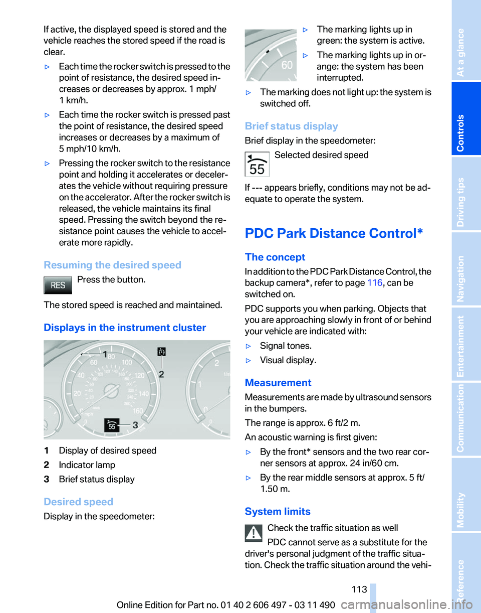
Displays in the instrument cluster 1
Display of desired speed
2 Indicator lamp
3 Brief status display
Desired speed
Display in the speedometer: ▷
The marking lights up in
green: the system is active.
▷ The marking lights up in or‐
ange: the system has been
interrupted.
▷ The marking does not light up: the system is
switched off.
Brief status display
Brief display in the speedometer: Selected desired speed
If --- appears briefly, conditions may not be ad‐
equate to operate the system.
PDC Park Distance Control*
The concept
In
addition to the PDC Park Distance Control, the
backup camera*, refer to page 116, can be
switched on.
PDC supports you when parking. Objects that
you are approaching slowly in front of or behind
your vehicle are indicated with:
▷ Signal tones.
▷ Visual display.
Measurement
Measurements
are made by ultrasound sensors
in the bumpers.
The range is approx. 6 ft/2 m.
An acoustic warning is first given:
▷ By the front* sensors and the two rear cor‐
ner sensors at approx. 24 in/60 cm.
▷ By the rear middle sensors at approx. 5 ft/
1.50 m.
System limits Check the traffic situation as well
PDC cannot serve as a substitute for the
driver's personal judgment of the traffic situa‐
tion.
Check the traffic situation around the vehi‐ Seite 113
113Online Edition for Part no. 01 40 2 606 497 - 03 11 490
Reference Mobility Communication Entertainment Navigation Driving tips
Controls At a glance
Page 115 of 299
▷
If the vehicle stops in front of an object that
is detected by only one of the corner sen‐
sors.
▷ If moving parallel to a wall.
The signal tone is switched off:
▷ When the vehicle moves away from an ob‐
ject by more than approx. 4 in/10 cm.
▷ When transmission position P is engaged.
Volume
You can set the volume of the PDC signal tone,
refer to page 171.
The
setting is stored for the remote control cur‐
rently in use.
Visual warning
The approach of the vehicle to an object can be
shown on the Control Display. Objects that are
farther away are displayed on the Control Dis‐
play before a signal tone sounds.
A display appears as soon as Park Distance
Control (PDC) is activated.
If the backup camera image was selected last, it
again appears on the display. To switch to PDC:
1. "Rear view camera" Select the symbol
on the Control Display.
2. Press the controller.
The setting is stored for the remote control cur‐
rently in use.
Zoom view*
On
the left part of the display screen, the vehicle
is shown enlarged. ▷
Transmission position D engaged: front
area of the vehicle. ▷
Transmission position R engaged: rear area
of the vehicle.
Display on the Control Display
Switching
on the backup camera via the
iDrive
With PDC activated: "Rear view camera"
The
backup camera image is displayed. The set‐
ting is stored for the remote control currently in
use.
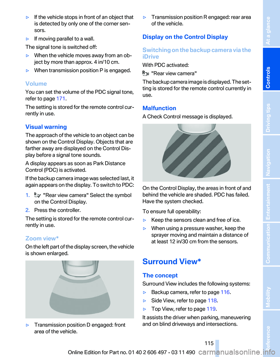
Malfunction
A Check Control message is displayed. On the Control Display, the areas in front of and
behind the vehicle are shaded. PDC has failed.
Have the system checked.
To ensure full operability:
▷
Keep the sensors clean and free of ice.
▷ When using a pressure washer, keep the
sprayer moving and maintain a distance of
at least 12 in/30 cm from the sensors.
Surround View*
The concept
Surround View includes the following systems:
▷ Backup camera, refer to page 116.
▷ Side View, refer to page 118.
▷ Top View, refer to page 119.
It assists the driver when parking, maneuvering
and on blind driveways and intersections.
Seite 115
115Online Edition for Part no. 01 40 2 606 497 - 03 11 490
Reference Mobility Communication Entertainment Navigation Driving tips
Controls At a glance
Page 117 of 299
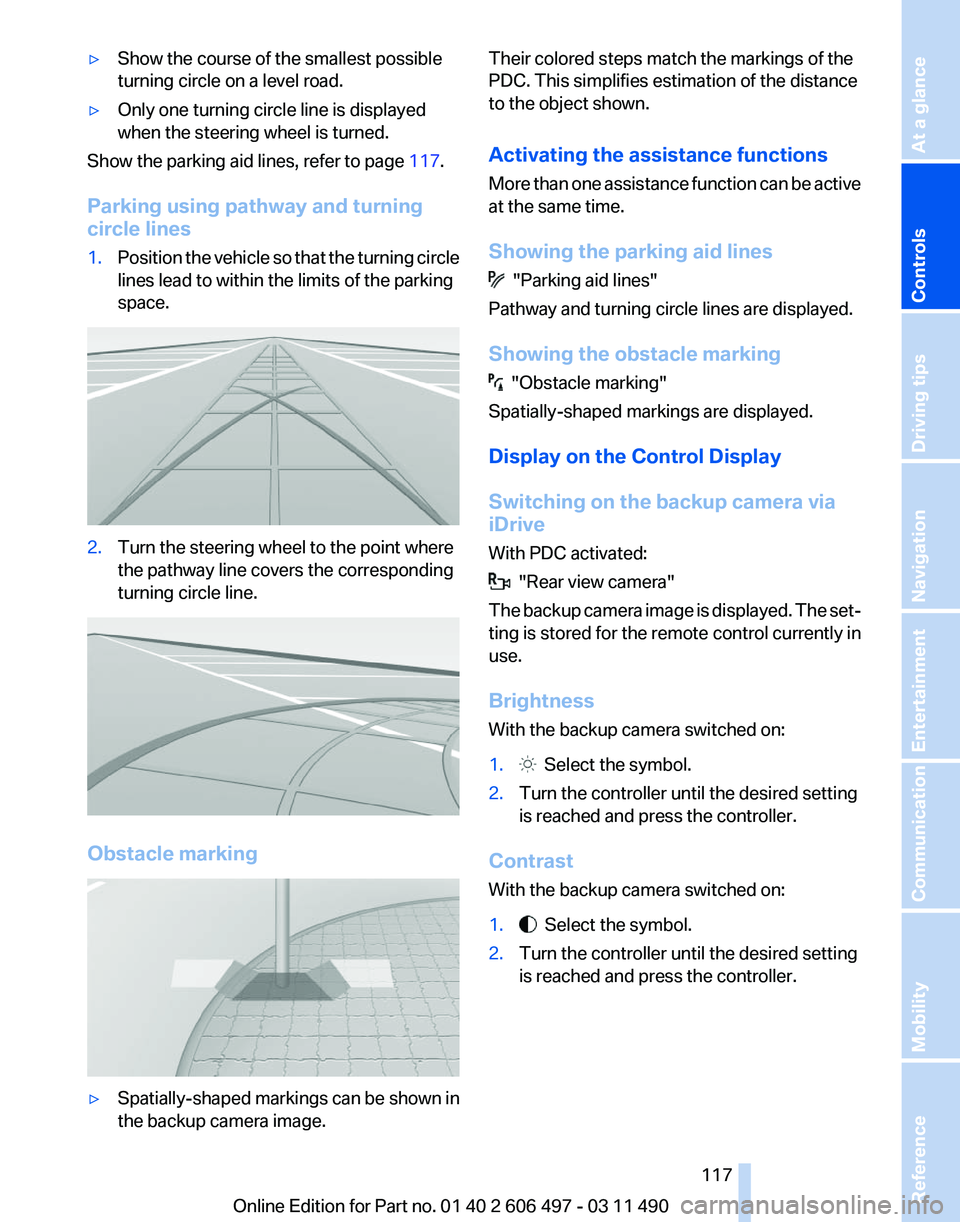
▷
Show the course of the smallest possible
turning circle on a level road.
▷ Only one turning circle line is displayed
when the steering wheel is turned.
Show the parking aid lines, refer to page 117.
Parking using pathway and turning
circle lines
1. Position the vehicle so that the turning circle
lines lead to within the limits of the parking
space. 2.
Turn the steering wheel to the point where
the pathway line covers the corresponding
turning circle line. Obstacle marking
▷
Spatially-shaped markings can be shown in
the backup camera image. Their colored steps match the markings of the
PDC. This simplifies estimation of the distance
to the object shown.
Activating the assistance functions
More
than one assistance function can be active
at the same time.
Showing the parking aid lines "Parking aid lines"
Pathway and turning circle lines are displayed.
Showing the obstacle marking "Obstacle marking"
Spatially-shaped markings are displayed.
Display on the Control Display
Switching on the backup camera via
iDrive
With PDC activated: "Rear view camera"
The
backup camera image is displayed. The set‐
ting is stored for the remote control currently in
use.
Brightness
With the backup camera switched on:
1. Select the symbol.
2. Turn the controller until the desired setting
is reached and press the controller.
Contrast
With the backup camera switched on:
1. Select the symbol.
2. Turn the controller until the desired setting
is reached and press the controller.
Seite 117
117Online Edition for Part no. 01 40 2 606 497 - 03 11 490
Reference Mobility Communication Entertainment Navigation Driving tips
Controls At a glance
Page 119 of 299
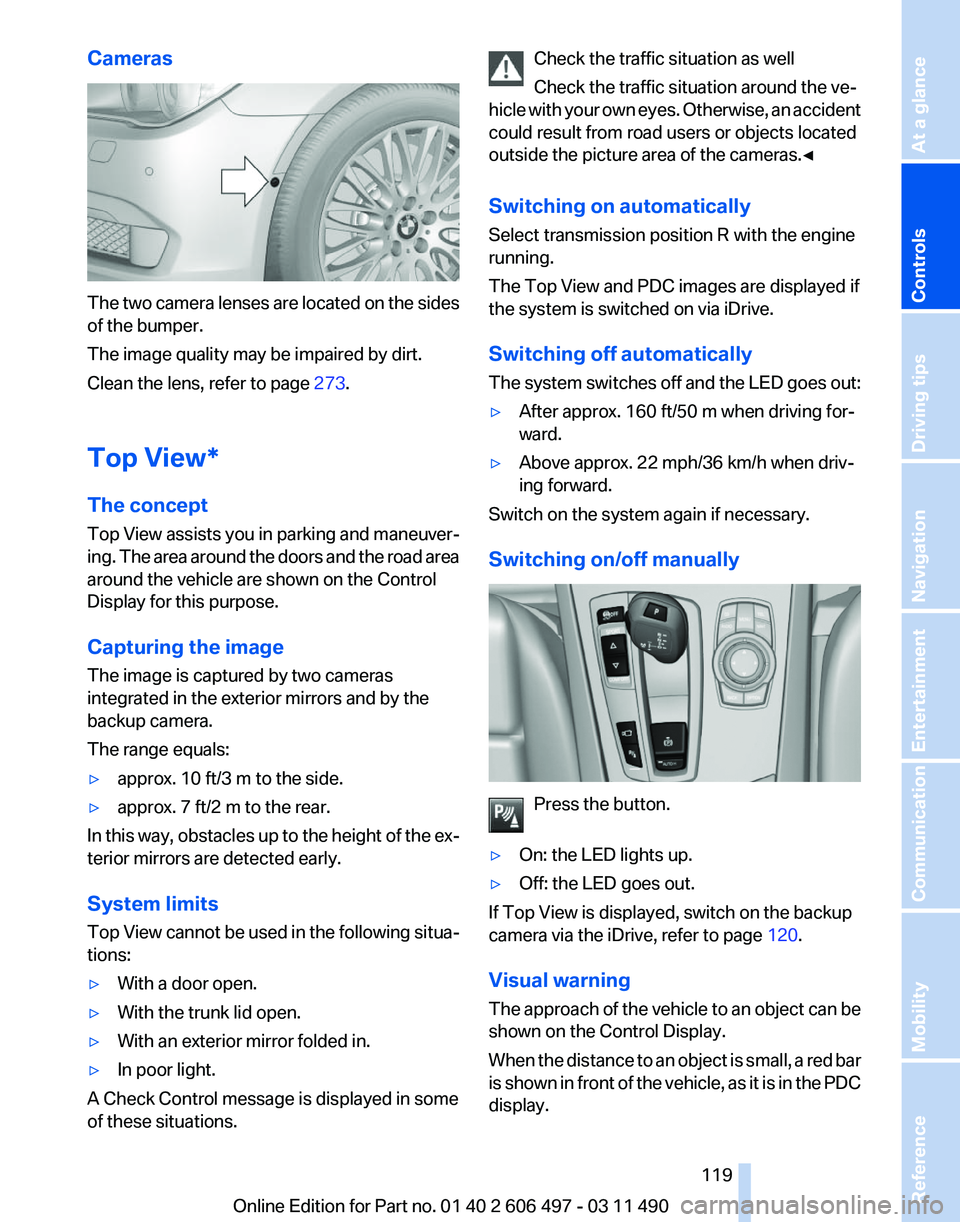
Cameras
The two camera lenses are located on the sides
of the bumper.
The image quality may be impaired by dirt.
Clean the lens, refer to page
273.
Top View*
The concept
Top
View assists you in parking and maneuver‐
ing. The area around the doors and the road area
around the vehicle are shown on the Control
Display for this purpose.
Capturing the image
The image is captured by two cameras
integrated in the exterior mirrors and by the
backup camera.
The range equals:
▷ approx. 10 ft/3 m to the side.
▷ approx. 7 ft/2 m to the rear.
In this way, obstacles up to the height of the ex‐
terior mirrors are detected early.
System limits
Top
View cannot be used in the following situa‐
tions:
▷ With a door open.
▷ With the trunk lid open.
▷ With an exterior mirror folded in.
▷ In poor light.
A Check Control message is displayed in some
of these situations. Check the traffic situation as well
Check the traffic situation around the ve‐
hicle
with your own eyes. Otherwise, an accident
could result from road users or objects located
outside the picture area of the cameras.◀
Switching on automatically
Select transmission position R with the engine
running.
The Top View and PDC images are displayed if
the system is switched on via iDrive.
Switching off automatically
The system switches off and the LED goes out:
▷ After approx. 160 ft/50 m when driving for‐
ward.
▷ Above approx. 22 mph/36 km/h when driv‐
ing forward.
Switch on the system again if necessary.
Switching on/off manually Press the button.
▷ On: the LED lights up.
▷ Off: the LED goes out.
If Top View is displayed, switch on the backup
camera via the iDrive, refer to page 120.
Visual warning
The
approach of the vehicle to an object can be
shown on the Control Display.
When the distance to an object is small, a red bar
is shown in front of the vehicle, as it is in the PDC
display. Seite 119
119Online Edition for Part no. 01 40 2 606 497 - 03 11 490
Reference Mobility Communication Entertainment Navigation Driving tips
Controls At a glance