traction control BMW 745i 2005 E65 Owner's Manual
[x] Cancel search | Manufacturer: BMW, Model Year: 2005, Model line: 745i, Model: BMW 745i 2005 E65Pages: 239, PDF Size: 8.03 MB
Page 15 of 239
At a glance
13Reference
Controls
Driving tips
Communications
Navigation
Entertainment
Mobility
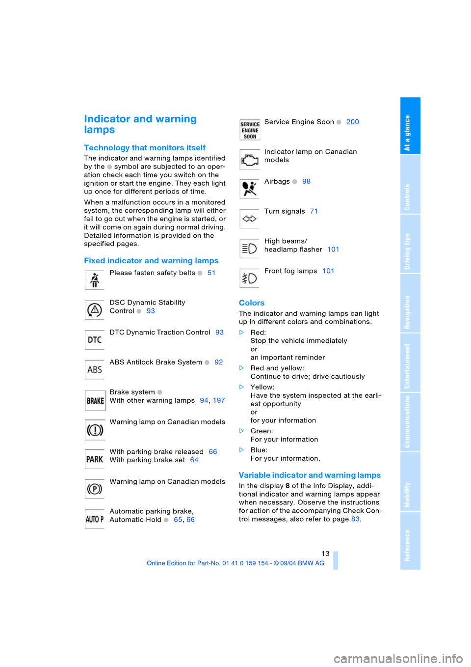
Indicator and warning
lamps
Technology that monitors itself
The indicator and warning lamps identified
by the
+ symbol are subjected to an oper-
ation check each time you switch on the
ignition or start the engine. They each light
up once for different periods of time.
When a malfunction occurs in a monitored
system, the corresponding lamp will either
fail to go out when the engine is started, or
it will come on again during normal driving.
Detailed information is provided on the
specified pages.
Fixed indicator and warning lamps
Colors
The indicator and warning lamps can light
up in different colors and combinations.
>Red:
Stop the vehicle immediately
or
an important reminder
>Red and yellow:
Continue to drive; drive cautiously
>Yellow:
Have the system inspected at the earli-
est opportunity
or
for your information
>Green:
For your information
>Blue:
For your information.
Variable indicator and warning lamps
In the display 8 of the Info Display, addi-
tional indicator and warning lamps appear
when necessary. Observe the instructions
for action of the accompanying Check Con-
trol messages, also refer to page83. Please fasten safety belts
+51
DSC Dynamic Stability
Control
+93
DTC Dynamic Traction Control93
ABS Antilock Brake System
+92
Brake system
+
With other warning lamps94,197
Warning lamp on Canadian models
With parking brake released66
With parking brake set64
Warning lamp on Canadian models
Automatic parking brake,
Automatic Hold
+65,66
Service Engine Soon +200
Indicator lamp on Canadian
models
Airbags
+98
Turn signals71
High beams/
headlamp flasher101
Front fog lamps101
Page 19 of 239
At a glance
17Reference
Controls
Driving tips
Communications
Navigation
Entertainment
Mobility
Control Center
The concept
The Control Center has been designed to
avoid the unnecessary complexity created
by an extended number of switches and
controls. It consists of the controller and
the Control Display.
The controller is used to select the func-
tions that will appear on the Control Dis-
play. In addition, it also shows you the
Check Control messages, refer to page83.
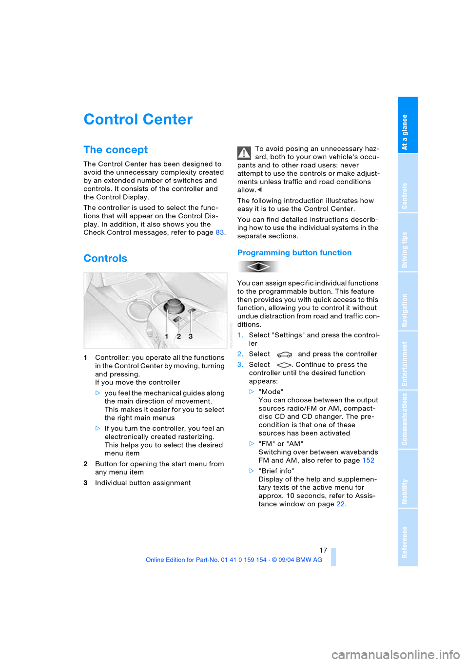
Controls
1Controller: you operate all the functions
in the Control Center by moving, turning
and pressing.
If you move the controller
>you feel the mechanical guides along
the main direction of movement.
This makes it easier for you to select
the right main menus
>If you turn the controller, you feel an
electronically created rasterizing.
This helps you to select the desired
menu item
2Button for opening the start menu from
any menu item
3Individual button assignmentTo avoid posing an unnecessary haz-
ard, both to your own vehicle's occu-
pants and to other road users: never
attempt to use the controls or make adjust-
ments unless traffic and road conditions
allow.<
The following introduction illustrates how
easy it is to use the Control Center.
You can find detailed instructions describ-
ing how to use the individual systems in the
separate sections.
Programming button function
You can assign specific individual functions
to the programmable button. This feature
then provides you with quick access to this
function, allowing you to control it without
undue distraction from road and traffic con-
ditions.
1.Select "Settings" and press the control-
ler
2.Select and press the controller
3.Select . Continue to press the
controller until the desired function
appears:
>"Mode"
You can choose between the output
sources radio/FM or AM, compact-
disc CD and CD changer. The pre-
condition is that one of these
sources has been activated
>"FM" or "AM"
Switching over between wavebands
FM and AM, also refer to page152
>"Brief info"
Display of the help and supplemen-
tary texts of the active menu for
approx. 10 seconds, refer to Assis-
tance window on page22.
Page 56 of 239
Adjustments
54 The mirrors automatically revert to their
clear, undimmed mode whenever you
engage transmission position R.
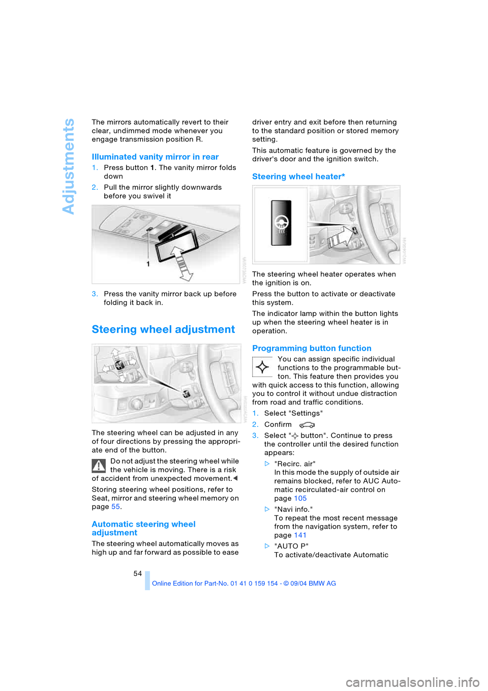
Illuminated vanity mirror in rear
1.Press button1. The vanity mirror folds
down
2.Pull the mirror slightly downwards
before you swivel it
3.Press the vanity mirror back up before
folding it back in.
Steering wheel adjustment
The steering wheel can be adjusted in any
of four directions by pressing the appropri-
ate end of the button.
Do not adjust the steering wheel while
the vehicle is moving. There is a risk
of accident from unexpected movement.<
Storing steering wheel positions, refer to
Seat, mirror and steering wheel memory on
page55.
Automatic steering wheel
adjustment
The steering wheel automatically moves as
high up and far forward as possible to ease driver entry and exit before then returning
to the standard position or stored memory
setting.
This automatic feature is governed by the
driver's door and the ignition switch.
Steering wheel heater*
The steering wheel heater operates when
the ignition is on.
Press the button to activate or deactivate
this system.
The indicator lamp within the button lights
up when the steering wheel heater is in
operation.
Programming button function
You can assign specific individual
functions to the programmable but-
ton. This feature then provides you
with quick access to this function, allowing
you to control it without undue distraction
from road and traffic conditions.
1.Select "Settings"
2.Confirm
3.Select " button". Continue to press
the controller until the desired function
appears:
>"Recirc. air"
In this mode the supply of outside air
remains blocked, refer to AUC Auto-
matic recirculated-air control on
page105
>"Navi info."
To repeat the most recent message
from the navigation system, refer to
page141
>"AUTO P"
To activate/deactivate Automatic
Page 61 of 239
Controls
59Reference
At a glance
Driving tips
Communications
Navigation
Entertainment
Mobility
child restraint system and the affected
vehicle safety-belt system checked and,
if necessary, replaced. Only have corre-
sponding work carried out by a BMW cen-
ter or a workshop that uses personnel
trained in accordance with BMW require-
ments.<
Commercially-available child-restraint sys-
tems are designed to be secured with a lap
belt or with the lap belt portion of a combi-
nation lap/shoulder belt. Improperly or
inadequately installed restraint systems
can increase the risk of injury to children.
Always read and follow the instructions that
come with the system.
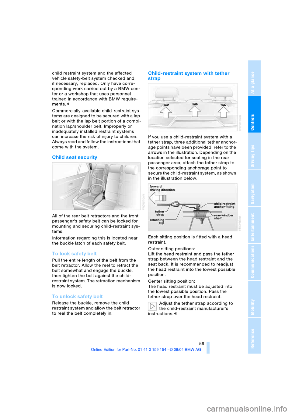
Child seat security
All of the rear belt retractors and the front
passenger's safety belt can be locked for
mounting and securing child-restraint sys-
tems.
Information regarding this is located near
the buckle latch of each safety belt.
To lock safety belt
Pull the entire length of the belt from the
belt retractor. Allow the reel to retract the
belt somewhat and engage the buckle,
then tighten the belt against the child-
restraint system. The retraction mechanism
is now locked.
To unlock safety belt
Release the buckle, remove the child-
restraint system and allow the belt retractor
to reel the belt completely in.
Child-restraint system with tether
strap
If you use a child-restraint system with a
tether strap, three additional tether anchor-
age points have been provided, refer to the
arrows in the illustration. Depending on the
location selected for seating in the rear
passenger area, attach the tether strap to
the corresponding anchorage point to
secure the child-restraint system, as shown
in the illustration below.
Each sitting position is fitted with a head
restraint.
Outer sitting positions:
Lift the head restraint and pass the tether
strap between the head restraint and the
seat back. It is recommended to readjust
the head restraint into the lowest possible
position.
Center sitting position:
The head restraint must be adjusted into
the lowest possible position. Pass the
tether strap over the head restraint.
Adjust the tether strap according to
the child-restraint manufacturer's
instructions.<
Page 67 of 239
Controls
65Reference
At a glance
Driving tips
Communications
Navigation
Entertainment
Mobility
time.
The brake lamps come on.
The vehicle continues to brake automati-
cally for as long as you maintain pressure
on the button.<
When you brake the vehicle to a vir-
tual stop, i.e., down to a speed of
approximately 2 mph/3 km/h or below, the
parking brake remains engaged.
The indicator lamp in the Info Display
lights up red. Briefly press the button to
disengage the parking brake manually.<
Automatic Hold
You can activate this feature after starting
the engine; it then remains operational until
the next time the engine is switched off.
This feature provides supplementary sup-
port during vehicle operation by automati-
cally engaging and releasing the parking
brake during stops at traffic lights, in stop-
and-go traffic, etc. As the vehicle then no
longer tends to creep when the transmis-
sion is engaged, it is no longer necessary to
hold the vehicle by pressing the brake
pedal.
It prevents the vehicle from rolling back-
ward during uphill starts.
The parking brake engages automatically
when you stop the vehicle and switch off
the engine.
You can activate or cancel the Automatic
Hold feature by selecting the "Settings"
menu in the Control Center. A description
of the Control Center is provided on
page17.
Automatic Hold activation/
deactivation
1.Select "Settings"
2.Select and confirm
3.Select "AUTO P". Press the controller
to activate/deactivate the desired func-
tion
>Automatic Hold is activated.
The green AUTO P status message in
the Info Display shows you that the sys-
tem is ready for operation >Automatic Hold is deactivated.
The green AUTO P status message dis-
appears from the Info Display.
You can assign the Automatic Hold
function to the programmable button
on the steering wheel, refer to page54.
This feature then provides you with quick
access to the Automatic Hold function,
allowing you to control it without undue dis-
traction from road and traffic conditions.<
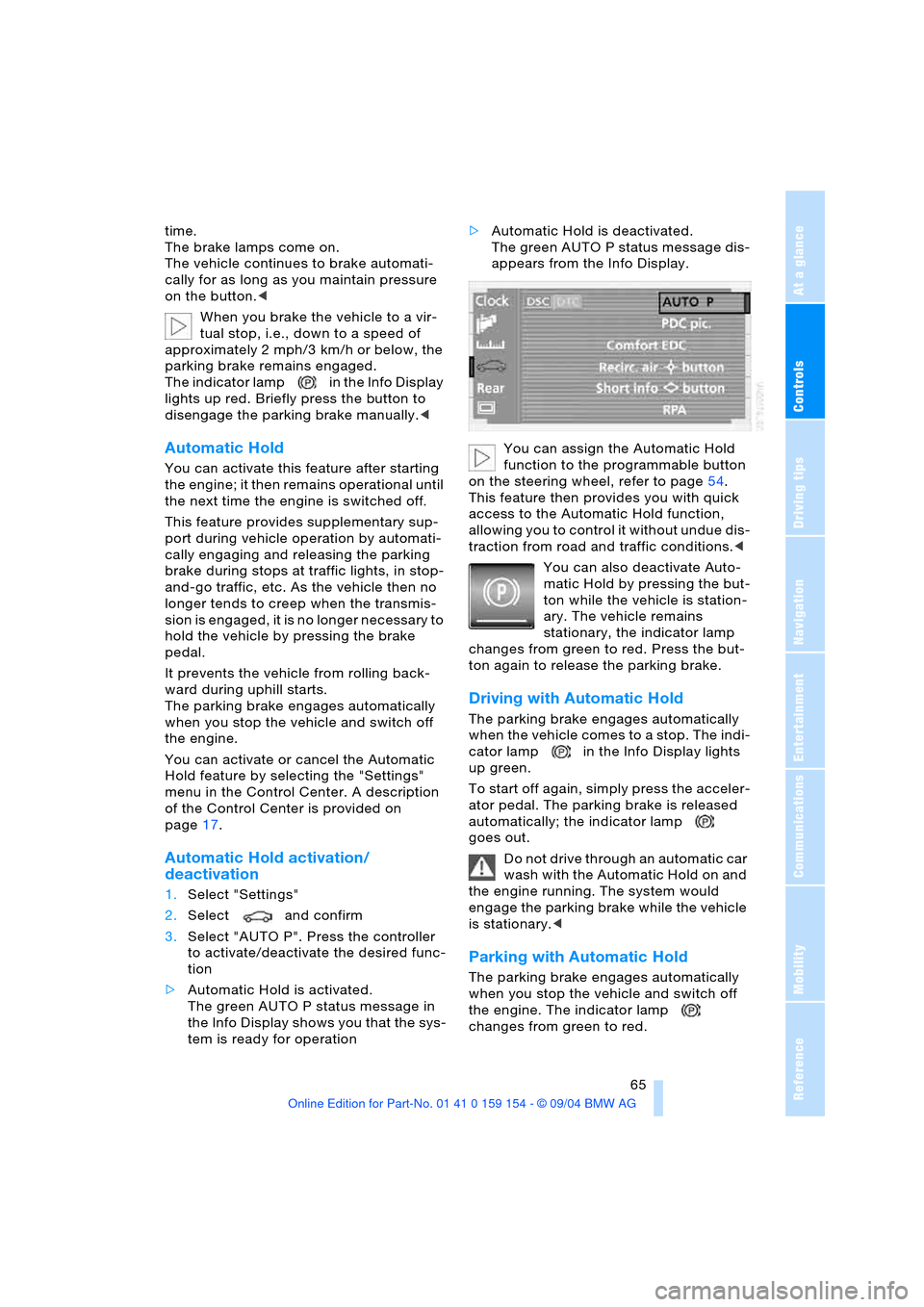
You can also deactivate Auto-
matic Hold by pressing the but-
ton while the vehicle is station-
ary. The vehicle remains
stationary, the indicator lamp
changes from green to red. Press the but-
ton again to release the parking brake.
Driving with Automatic Hold
The parking brake engages automatically
when the vehicle comes to a stop. The indi-
cator lamp in the Info Display lights
up green.
To start off again, simply press the acceler-
ator pedal. The parking brake is released
automatically; the indicator lamp
goes out.
Do not drive through an automatic car
wash with the Automatic Hold on and
the engine running. The system would
engage the parking brake while the vehicle
is stationary.<
Parking with Automatic Hold
The parking brake engages automatically
when you stop the vehicle and switch off
the engine. The indicator lamp
changes from green to red.
Page 95 of 239
Controls
93Reference
At a glance
Driving tips
Communications
Navigation
Entertainment
Mobility
EBV Electronic brake-force
distribution
EBV controls the brake system's applica-
tion pressure at the rear wheels to ensure
stable deceleration.
DSC Dynamic Stability Control
The system optimizes vehicle stability dur-
ing acceleration and when starting from a
full stop, as well as optimizing traction.
The system recognizes any tendency for
the vehicle to assume an unstable attitude
such as oversteer or understeer; it then
counteracts this tendency with a combina-
tion of graduated reductions in engine
torque and selective braking intervention at
individual wheels. DSC provides optimized
stability within the limits defined by the
laws of physics.
The DSC is operational every time you start
the engine. DSC contains the functions
DTC Dynamic Traction Control and DBC
Dynamic Brake Control.
Indicator lamp
The indicator lamp goes out shortly
after the engine starts.
The indicator lamp flashes:
DSC controls the drive and braking forces.
The indicator lamp stays lit:
DSC has been switched off using the Con-
trol Center.
Activating DTC Dynamic Traction
Control
In particular driving situations, in deep
snow, for example, DTC ensures the maxi-
mum forward momentum. The gain in for-
ward momentum in these situations
involves a reduction in vehicle stability.
DTC is active up to 45 mph/70 km/h.You may find it useful to briefly activate
DTC under the following special circum-
stances:
>When rocking the vehicle and starting
off in deep snow or on loose road sur-
faces
>When ascending snow-covered hills,
and when driving in deep or on hard-
packed snow
>When driving with snow chains.
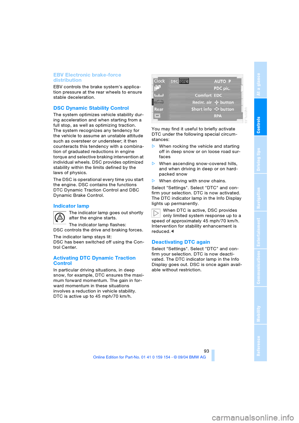
Select "Settings". Select "DTC" and con-
firm your selection. DTC is now activated.
The DTC indicator lamp in the Info Display
lights up permanently.
When DTC is active, DSC provides
only limited system response up to a
speed of approximately 45 mph/70 km/h.
Intervention for stability enhancement is
reduced.<
Deactivating DTC again
Select "Settings". Select "DTC" and con-
firm your selection. DTC is now deacti-
vated. The DTC indicator lamp in the Info
Display goes out. DSC is once again avail-
able without restriction.
Page 96 of 239
Technology for comfort, convenience and safety
94
Switching off DSC
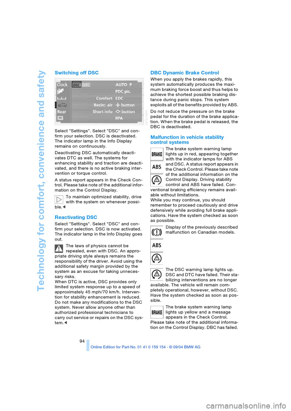
Select "Settings". Select "DSC" and con-
firm your selection. DSC is deactivated.
The indicator lamp in the Info Display
remains on continuously.
Deactivating DSC automatically deacti-
vates DTC as well. The systems for
enhancing stability and traction are deacti-
vated, and there is no active braking inter-
vention or torque control.
A status report appears in the Check Con-
trol. Please take note of the additional infor-
mation on the Control Display.
To maintain optimized stability, drive
with the system on whenever possi-
ble.<
Reactivating DSC
Select "Settings". Select "DSC" and con-
firm your selection. DSC is now activated.
The indicator lamp in the Info Display goes
out.
The laws of physics cannot be
repealed, even with DSC. An appro-
priate driving style always remains the
responsibility of the driver. Avoid using the
additional safety margin provided by the
system as an excuse for taking unneces-
sary risks.
When DTC is active, DSC provides only
limited system response up to a speed of
approximately 45 mph/70 km/h. Interven-
tion for stability enhancement is reduced.
Do not make any modifications to the DSC
system. Never allow anyone other than
authorized professional technicians to
carry out service or repairs on the DSC sys-
tem.<
DBC Dynamic Brake Control
When you apply the brakes rapidly, this
system automatically produces the maxi-
mum braking force boost and thus helps to
achieve the shortest possible braking dis-
tance during panic stops. This system
exploits all of the benefits provided by ABS.
Do not reduce the pressure on the brake
pedal for the duration of the brake applica-
tion. When the brake pedal is released, the
DBC is deactivated.
Malfunction in vehicle stability
control systems
The brake system warning lamp
lights up in red, appearing together
with the indicator lamps for ABS
and DSC. A status report appears in
the Check Control. Please take note
of the additional information on the
Control Display. Driving stability
control and ABS have failed. Con-
ventional braking efficiency remains avail-
able without limitations.
While you may continue, you should
remember to proceed cautiously and drive
defensively while avoiding full brake appli-
cations. Have the system checked as soon
as possible.
Display of the previously described
malfunction on Canadian models.
The DSC warning lamp lights up.
DSC and DTC have failed. Their sta-
bilizing interventions are no longer
available. The vehicle will remain com-
pletely operational, however, without DSC.
Have the system checked as soon as pos-
sible.
The brake system warning lamp
lights up yellow and a message
appears in the Check Control.
Please take note of the additional informa-
tion on the Control Display. DBC has failed.
Page 124 of 239
Things to remember when driving
122
Things to remember when driving
Break-in procedures
To ensure that your vehicle continues to
furnish optimized economy of operation
throughout an extended service life, we
request that you devote careful attention
to the following information.
Engine and differential
Up to 1,200 miles/2,000 km:
During this initial period you should attempt
to avoid constant, steady-state operation
and vary both vehicle and engine speeds
as often as possible. Until the break-in
period has been completed you should
also refrain from exceeding the following:
>4,500 rpm or 105 mph/170 km/h
Always obey all official speed limits.
Avoid full-throttle operation and use of the
transmission's kick-down mode during
these initial miles.
Once you have driven 1,200 miles/
2,000 km, the engine or vehicle speeds can
be gradually increased.
Tires
Due to technical factors associated with
their manufacture, tires do not achieve their
full traction potential until after an initial
break-in period. Therefore, drive reservedly
during the first 200 miles/300 km.
Brake system
Brakes require an initial break-in period of
approx. 300 miles/500 km to achieve opti-
mized contact and wear patterns between
brake pads and rotors.
Following component replacements
Observe the break-in instructions again if
previously addressed components must be
replaced again during driving later.
General driving notes
Hot exhaust system
Extreme temperatures occur at the
catalytic converter on this and every
catalyst-equipped vehicle. Do not remove
the heat shields installed adjacent to vari-
ous sections of the exhaust system, and
never apply undercoating to them. When
driving, standing at idle and while parking
take care to avoid possible contact
between the hot exhaust system and any
highly flammable materials such as hay,
leaves, grass, etc. Such contact could lead
to a fire, accompanied by the risk of serious
property damage as well as personal
injury.<
Air conditioning
Condensation forms in the air conditioner
system during operation, and then exits
under the vehicle. Traces of condensed
water under the vehicle are thus normal.
Before driving into a car wash
1.Fold in the exterior mirrors, refer to
page53, as otherwise they could be
damaged due to the width of the vehicle
2.Leave the remote control in the ignition
lock, as otherwise the P position of the
automatic transmission will automati-
cally be selected when the remote con-
trol is removed. Refer to page63
and69.
With Comfort Access, be sure to
observe the instructions on page63
3.Release the parking brake, especially
when you have activated Automatic
Hold. Refer to page64 and65.
Page 137 of 239
Navigation
Driving tips
135Reference
At a glance
Controls
Communications
Entertainment
Mobility
Map-guided destination
selection
Assume that you only know the general
location of your destination's street or
locality. You also have the option of select-
ing the destination on a map using a target
cursor and importing it into the destination
guidance.
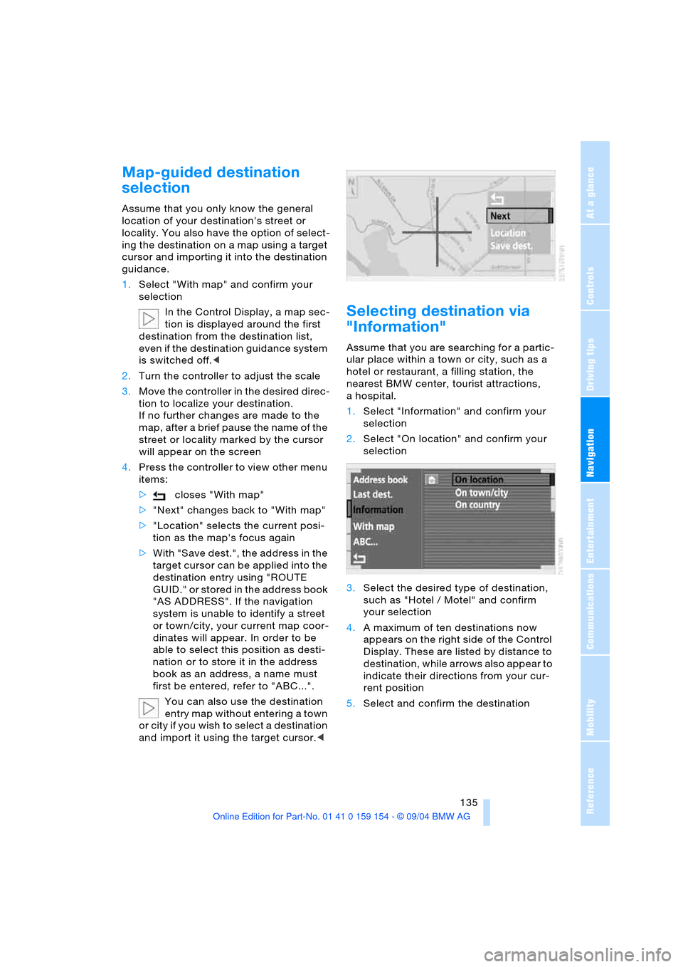
1.Select "With map" and confirm your
selection
In the Control Display, a map sec-
tion is displayed around the first
destination from the destination list,
even if the destination guidance system
is switched off.<
2.Turn the controller to adjust the scale
3.Move the controller in the desired direc-
tion to localize your destination.
If no further changes are made to the
map, after a brief pause the name of the
street or locality marked by the cursor
will appear on the screen
4.Press the controller to view other menu
items:
>closes "With map"
>"Next" changes back to "With map"
>"Location" selects the current posi-
tion as the map's focus again
>With "Save dest.", the address in the
target cursor can be applied into the
destination entry using "ROUTE
GUID." or stored in the address book
"AS ADDRESS". If the navigation
system is unable to identify a street
or town/city, your current map coor-
dinates will appear. In order to be
able to select this position as desti-
nation or to store it in the address
book as an address, a name must
first be entered, refer to "ABC...".
You can also use the destination
entry map without entering a town
or city if you wish to select a destination
and import it using the target cursor.<
Selecting destination via
"Information"
Assume that you are searching for a partic-
ular place within a town or city, such as a
hotel or restaurant, a filling station, the
nearest BMW center, tourist attractions,
ahospital.
1.Select "Information" and confirm your
selection
2.Select "On location" and confirm your
selection
3.Select the desired type of destination,
such as "Hotel / Motel" and confirm
your selection
4.A maximum of ten destinations now
appears on the right side of the Control
Display. These are listed by distance to
destination, while arrows also appear to
indicate their directions from your cur-
rent position
5.Select and confirm the destination
Page 192 of 239
Wheels and tires
190
Tire identification marks
Knowledge of the labeling on the side of
the tire makes it easier to identify and
choose the right tires.
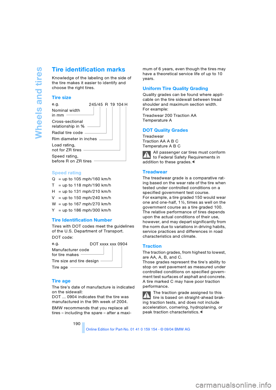
Tire size
Speed rating
Q = up to 105 mph/160 km/h
T = up to 118 mph/190 km/h
H = up to 131 mph/210 km/h
V = up to 150 mph/240 km/h
W = up to 167 mph/270 km/h
Y = up to 186 mph/300 km/h
Tire Identification Number
Tires with DOT codes meet the guidelines
of the U.S. Department of Transport.
DOT code:
Tire age
The tire's date of manufacture is indicated
on the sidewall:
DOT ... 0904 indicates that the tire was
manufactured in the 9th week of 2004.
BMW recommends that you replace all
tires – including the spare – after a maxi-mum of 6 years, even though the tires may
have a theoretical service life of up to 10
years.
Uniform Tire Quality Grading
Quality grades can be found where appli-
cable on the tire sidewall between tread
shoulder and maximum section width.
For example:
Treadwear 200 Traction AA
Temperature A
DOT Quality Grades
Treadwear
Traction AA A B C
Temperature A B C
All passenger car tires must conform
to Federal Safety Requirements in
addition to these grades.<
Treadwear
The treadwear grade is a comparative rat-
ing based on the wear rate of the tire when
tested under controlled conditions on a
specified government test course.
For example, a tire graded 150 would wear
one and one-half, 1γ, times as well on the
government course as a tire graded 100.
The relative performance of tires depends
upon the actual conditions of their use,
however, and may depart significantly from
the norm due to variations in driving habits,
service practices and differences in road
characteristics and climate.
Traction
The traction grades, from highest to lowest,
are AA, A, B, and C.
Those grades represent the tire's ability to
stop on wet pavement as measured under
controlled conditions on specified govern-
ment test surfaces of asphalt and concrete.
A tire marked C may have poor traction
performance.
The traction grade assigned to this
tire is based on straight-ahead brak-
ing traction tests, and does not include
acceleration, cornering, hydroplaning, or
peak traction characteristics.< e.g.
Nominal width
in mm
Cross-sectional
relationship in Ξ
Radial tire code
Rim diameter in inches
Load rating,
not for ZR tires
Speed rating,
before R on ZR tires
245/45 R19104H
e.g.
Manufacturer code
for tire makes
Tire size and tire design
Tire ageDOT xxxx xxx 0904