display BMW 750IL 1994 E38 Central Body Electronics ZKE Manual
[x] Cancel search | Manufacturer: BMW, Model Year: 1994, Model line: 750IL, Model: BMW 750IL 1994 E38Pages: 80, PDF Size: 4.14 MB
Page 62 of 80

Driver’s Seat (E38/E39)
Principle of Operation
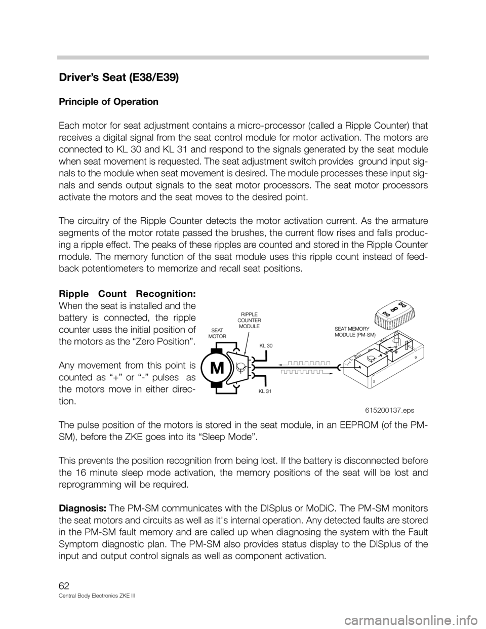
Each motor for seat adjustment contains a micro-processor (called a Ripple Counter) that
receives a digital signal from the seat control module for motor activation. The motors are
connected to KL 30 and KL 31 and respond to the signals generated by the seat module
when seat movement is requested. The seat adjustment switch provides ground input sig-
nals to the module when seat movement is desired. The module processes these input sig-
nals and sends output signals to the seat motor processors. The seat motor processors
activate the motors and the seat moves to the desired point.
The circuitry of the Ripple Counter detects the motor activation current. As the armature
segments of the motor rotate passed the brushes, the current flow rises and falls produc-
ing a ripple effect. The peaks of these ripples are counted and stored in the Ripple Counter
module. The memory function of the seat module uses this ripple count instead of feed-
back potentiometers to memorize and recall seat positions.
Ripple Count Recognition:
When the seat is installed and the
battery is connected, the ripple
counter uses the initial position of
the motors as the “Zero Position”.
Any movement from this point is
counted as “+” or “-” pulses as
the motors move in either direc-
tion.
The pulse position of the motors is stored in the seat module, in an EEPROM (of the PM-
SM), before the ZKE goes into its “Sleep Mode”.
This prevents the position recognition from being lost. If the battery is disconnected before
the 16 minute sleep mode activation, the memory positions of the seat will be lost and
reprogramming will be required.
Diagnosis: The PM-SM communicates with the DISplus or MoDiC. The PM-SM monitors
the seat motors and circuits as well as it's internal operation. Any detected faults are stored
in the PM-SM fault memory and are called up when diagnosing the system with the Fault
Symptom diagnostic plan. The PM-SM also provides status display to the DISplus of the
input and output control signals as well as component activation.
62
Central Body Electronics ZKE III
615200137.eps