tire BMW 750LI 2011 F02 Owner's Manual
[x] Cancel search | Manufacturer: BMW, Model Year: 2011, Model line: 750LI, Model: BMW 750LI 2011 F02Pages: 299, PDF Size: 8.49 MB
Page 5 of 299
Contents
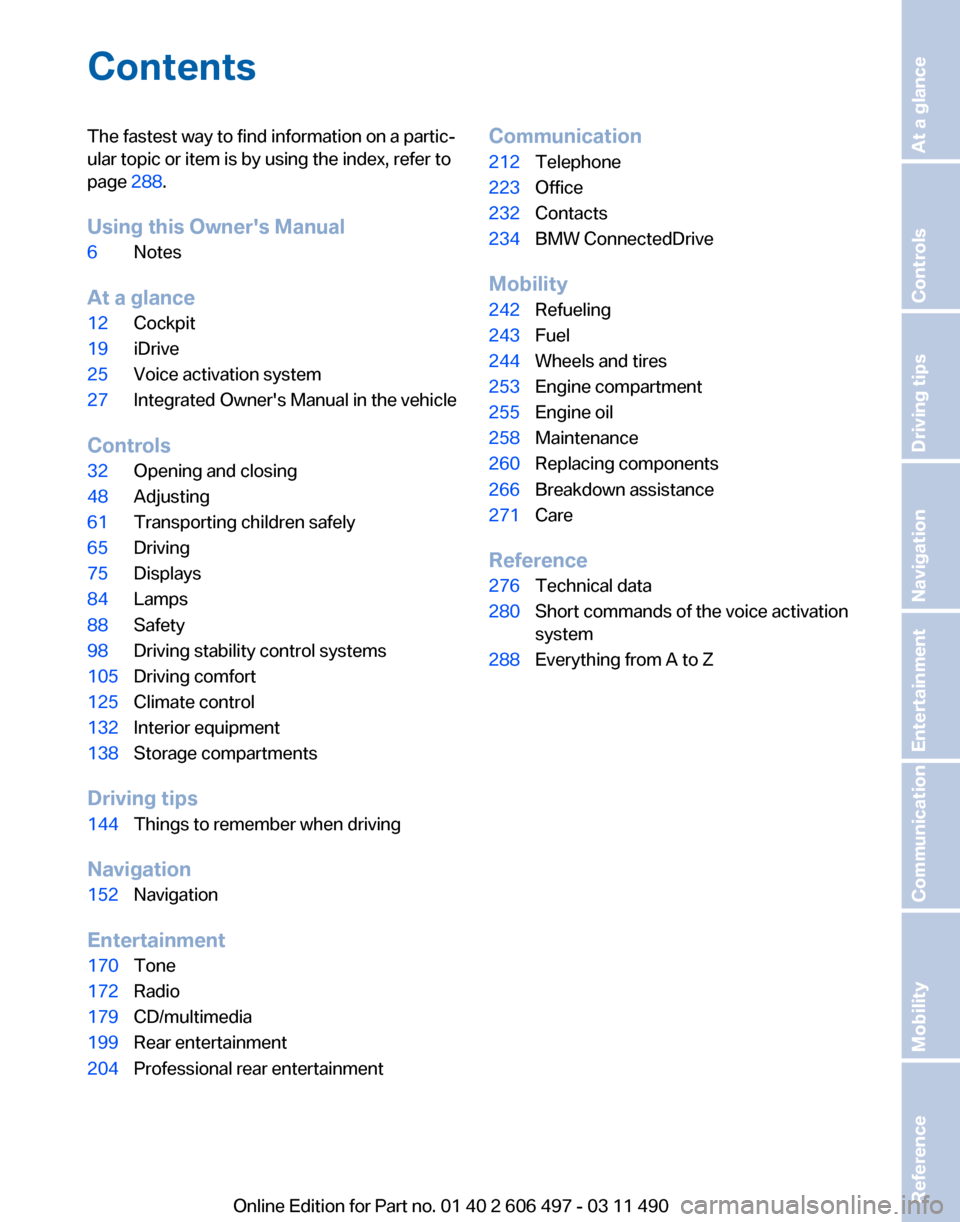
The fastest way to find information on a partic‐
ular topic or item is by using the index, refer to
page
288.
Using this Owner's Manual
6 Notes
At a glance
12 Cockpit
19 iDrive
25 Voice activation system
27 Integrated Owner's Manual in the vehicle
Controls
32 Opening and closing
48 Adjusting
61 Transporting children safely
65 Driving
75 Displays
84 Lamps
88 Safety
98 Driving stability control systems
105 Driving comfort
125 Climate control
132 Interior equipment
138 Storage compartments
Driving tips
144 Things to remember when driving
Navigation
152 Navigation
Entertainment
170 Tone
172 Radio
179 CD/multimedia
199 Rear entertainment
204 Professional rear entertainment Communication
212
Telephone
223 Office
232 Contacts
234 BMW ConnectedDrive
Mobility
242 Refueling
243 Fuel
244 Wheels and tires
253 Engine compartment
255 Engine oil
258 Maintenance
260 Replacing components
266 Breakdown assistance
271 Care
Reference
276 Technical data
280 Short commands of the voice activation
system
288 Everything from A to Z
Seite 5
Online Edition for Part no. 01 40 2 606 497 - 03 11 490 Reference Mobility Communication Entertainment Navigation Driving tips Controls At a glance
Page 6 of 299
Notes
Using this Owner's Manual
The fastest way to find information on a partic‐
ular topic is by using the index.
An initial overview of the vehicle is provided in
the first chapter.
Updates made after the editorial
deadline
Any
updates made after the editorial deadline for
the Owner's Manuals are located in the appen‐
dix of the printed quick reference for the vehicle.
Additional sources of information
Should you have any questions, your service
center will be glad to advise you at any time.
Information on BMW, e.g., on technology, is
available on the Internet: bmwusa.com.
Symbols Indicates precautions that must be followed
precisely
in order to avoid the possibility of per‐
sonal injury and serious damage to the vehicle.
◄ Marks the end of a specific item of informa‐
tion.
* Indicates special equipment, country-specific
equipment and optional accessories, as well as
equipment and functions not yet available at the
time of printing.
"..." Identifies Control Display texts used to se‐
lect individual functions.
›...‹ Verbal instructions to use with the voice ac‐
tivation system.
››...‹‹ Identifies the answers generated by the
voice activation system. Refers to measures that can be taken to help
protect the environment. Symbols on vehicle components Indicates that you should consult the rele‐
vant section of this Owner's Manual for infor‐
mation on a particular part or assembly.
Your individual vehicle
You
have decided in favor of a vehicle with indi‐
vidualized equipment and features.
This Owner's Manual describes the entire array
of options and equipment available for a specific
model.
As a result, the manual may contain accessories
and equipment that you may not have specified
for your own vehicle.
All options and special equipment are marked
with an asterisk *.
For options and equipment not described in this
Owner's Manual, please refer to the Supple‐
mentary Owner's Manuals.
On right-hand drive vehicles, some controls are
arranged differently than shown in the illustra‐
tions.
Status of the Owner's Manual
The manufacturer of your vehicle pursues a pol‐
icy of constant development that is conceived
to ensure that our vehicles continue to embody
the highest quality and safety standards. In rare
cases, therefore, the features described in this
Owner's Manual may differ from those in your
vehicle.
Updates made after the editorial
deadline
Any updates made after the editorial deadline for
the Owner's Manuals are located in the appen‐
dix of the printed quick reference for the vehicle.
Seite 6
6 Online Edition for Part no. 01 40 2 606 497 - 03 11 490Notes
Page 15 of 299
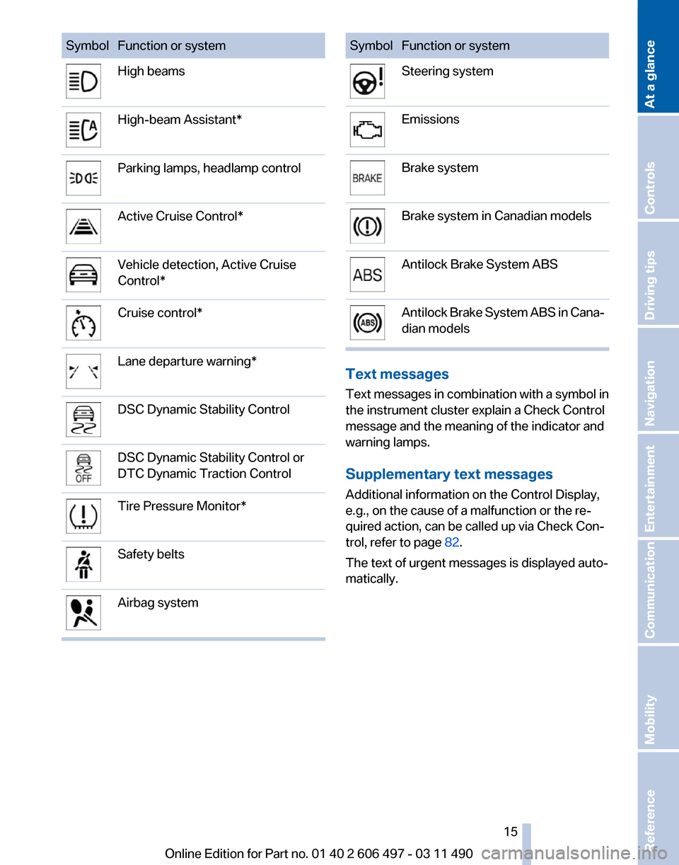
Symbol Function or system
High beams
High-beam Assistant*
Parking lamps, headlamp control
Active Cruise Control*
Vehicle detection, Active Cruise
Control*
Cruise control*
Lane departure warning*
DSC Dynamic Stability Control
DSC Dynamic Stability Control or
DTC Dynamic Traction Control
Tire Pressure Monitor*
Safety belts
Airbag system Symbol Function or system
Steering system
Emissions
Brake system
Brake system in Canadian models
Antilock Brake System ABS
Antilock Brake System ABS in Cana‐
dian models
Text messages
Text
messages in combination with a symbol in
the instrument cluster explain a Check Control
message and the meaning of the indicator and
warning lamps.
Supplementary text messages
Additional information on the Control Display,
e.g., on the cause of a malfunction or the re‐
quired action, can be called up via Check Con‐
trol, refer to page 82.
The text of urgent messages is displayed auto‐
matically.
Seite 15
15Online Edition for Part no. 01 40 2 606 497 - 03 11 490
Reference Mobility Communication Entertainment Navigation Driving tips Controls
At a glance
Page 27 of 299
Integrated Owner's Manual in the vehicle
The integrated Owner's Manual can be dis‐
played on the Control Display. The equipment
and functions that are in the vehicle are descri‐
bed therein.
Components of the
integrated Owner's Manual
The integrated Owner's Manual consists of
three parts, which offer various levels of infor‐
mation or access possibilities.
Quick Reference Guide
Located
in the Quick Reference is important in‐
formation for the operation of the vehicle, the
operation of basic vehicle functions or for what
to do in the event of a flat tire. This information
can also be displayed during driving.
Search by pictures
Information and descriptions based on illustra‐
tions can be searched via search by pictures.
This is helpful, for example, if the description of
an outfitting package that cannot be named is
needed.
Owner's Manual
Information and descriptions can be searched
by direct entry of a search term via the index.
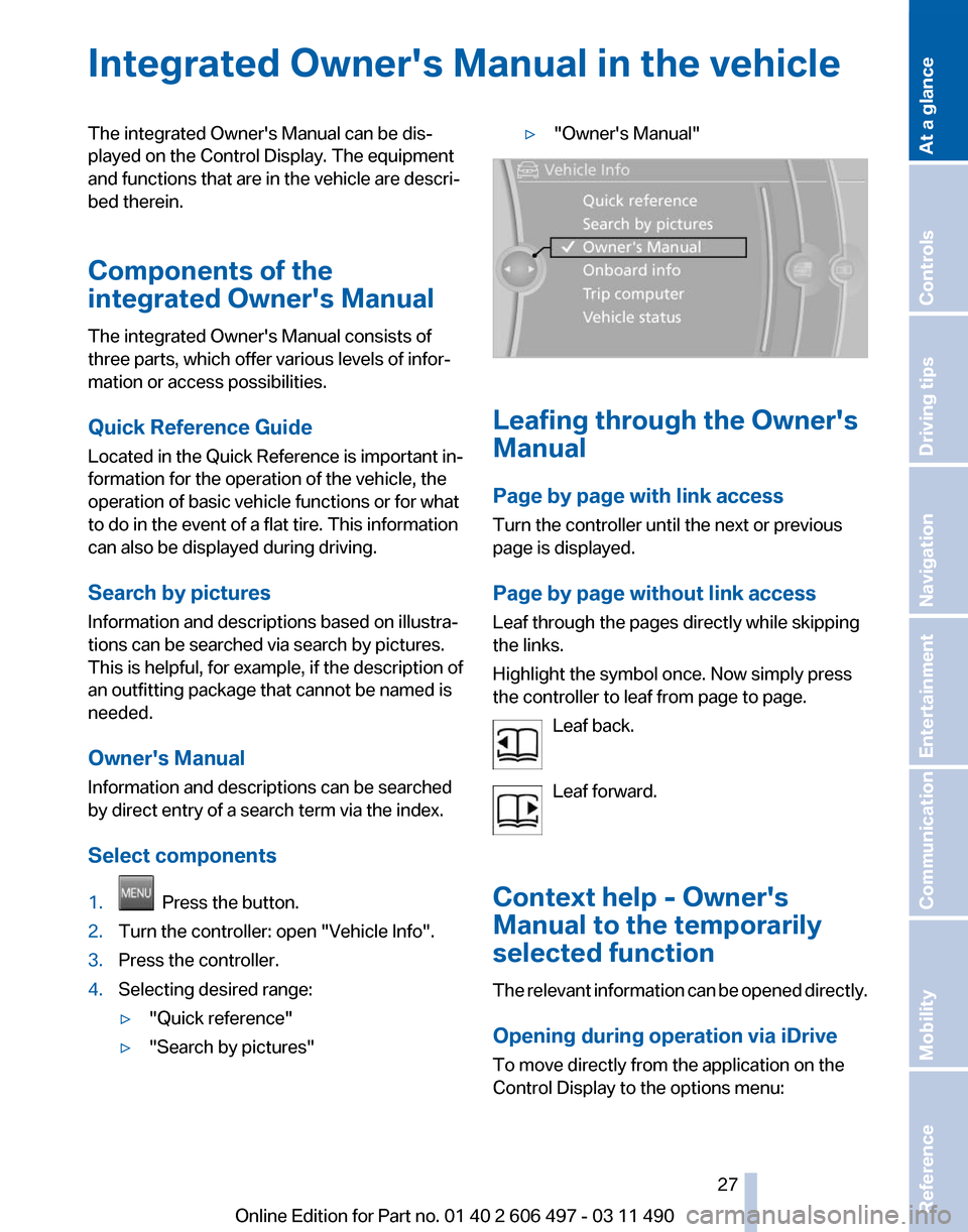
Select components
1. Press the button.
2. Turn the controller: open "Vehicle Info".
3. Press the controller.
4. Selecting desired range:
▷"Quick reference"
▷ "Search by pictures" ▷
"Owner's Manual" Leafing through the Owner's
Manual
Page by page with link access
Turn the controller until the next or previous
page is displayed.
Page by page without link access
Leaf through the pages directly while skipping
the links.
Highlight the symbol once. Now simply press
the controller to leaf from page to page.
Leaf back.
Leaf forward.
Context help - Owner's
Manual to the temporarily
selected function
The
relevant information can be opened directly.
Opening during operation via iDrive
To move directly from the application on the
Control Display to the options menu: Seite 27
27Online Edition for Part no. 01 40 2 606 497 - 03 11 490
Reference Mobility Communication Entertainment Navigation Driving tips Controls
At a glance
Page 36 of 299
▷
The alarm system*, refer to page 43, is
armed or disarmed.
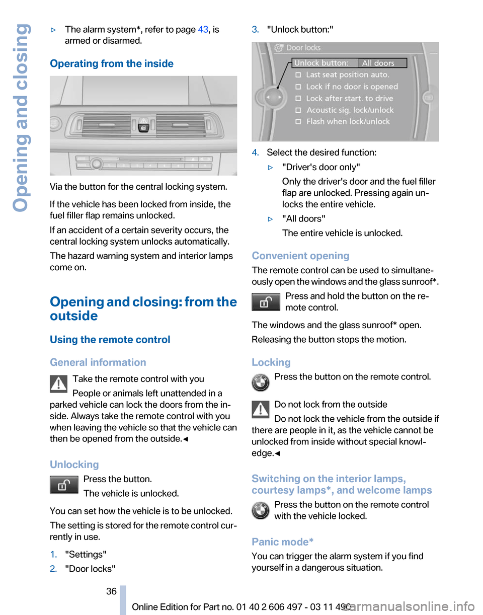
Operating from the inside Via the button for the central locking system.
If the vehicle has been locked from inside, the
fuel filler flap remains unlocked.
If an accident of a certain severity occurs, the
central locking system unlocks automatically.
The hazard warning system and interior lamps
come on.
Opening
and closing: from the
outside
Using the remote control
General information
Take the remote control with you
People or animals left unattended in a
parked vehicle can lock the doors from the in‐
side. Always take the remote control with you
when leaving the vehicle so that the vehicle can
then be opened from the outside.◀
Unlocking
Press the button.
The vehicle is unlocked.
You can set how the vehicle is to be unlocked.
The setting is stored for the remote control cur‐
rently in use.
1. "Settings"
2. "Door locks" 3.
"Unlock button:" 4.
Select the desired function:
▷"Driver's door only"
Only the driver's door and the fuel filler
flap are unlocked. Pressing again un‐
locks the entire vehicle.
▷ "All doors"
The entire vehicle is unlocked.
Convenient opening
The remote control can be used to simultane‐
ously
open the windows and the glass sunroof*.Press and hold the button on the re‐
mote control.
The windows and the glass sunroof* open.
Releasing the button stops the motion.
Locking Press the button on the remote control.
Do not lock from the outside
Do not lock the vehicle from the outside if
there are people in it, as the vehicle cannot be
unlocked from inside without special knowl‐
edge.◀
Switching on the interior lamps,
courtesy lamps*, and welcome lamps
Press the button on the remote control
with the vehicle locked.
Panic mode*
You can trigger the alarm system if you find
yourself in a dangerous situation. Seite 36
36 Online Edition for Part no. 01 40 2 606 497 - 03 11 490
Opening and closing
Page 50 of 299
Gentleman function*
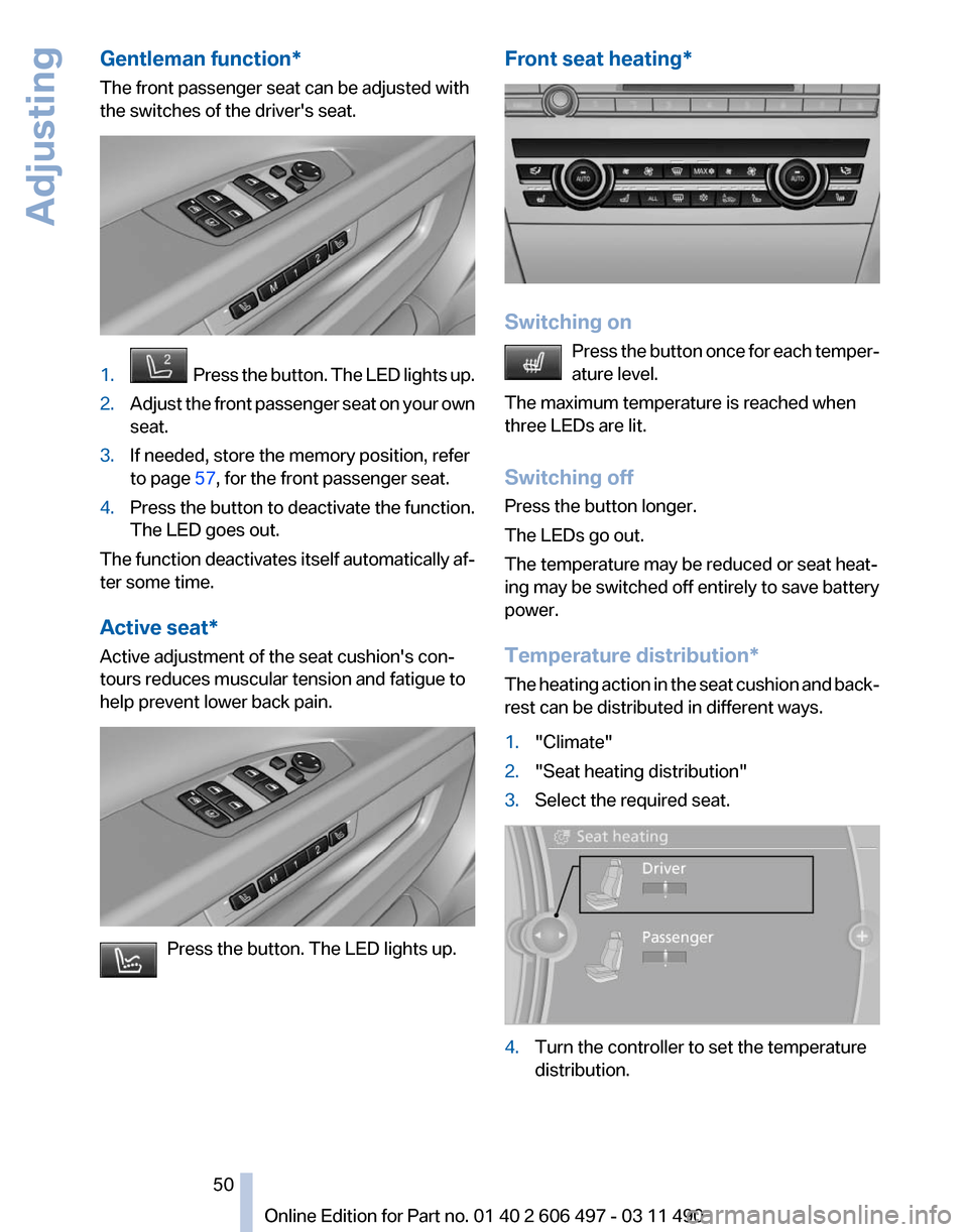
The front passenger seat can be adjusted with
the switches of the driver's seat.
1. Press the button. The LED lights up.
2. Adjust the front passenger seat on your own
seat.
3. If needed, store the memory position, refer
to page 57, for the front passenger seat.
4. Press the button to deactivate the function.
The LED goes out.
The function deactivates itself automatically af‐
ter some time.
Active seat*
Active adjustment of the seat cushion's con‐
tours reduces muscular tension and fatigue to
help prevent lower back pain. Press the button. The LED lights up. Front seat heating*
Switching on
Press the button once for each temper‐
ature level.
The maximum temperature is reached when
three LEDs are lit.
Switching off
Press the button longer.
The LEDs go out.
The temperature may be reduced or seat heat‐
ing may be switched off entirely to save battery
power.
Temperature distribution*
The heating action in the seat cushion and back‐
rest can be distributed in different ways.
1. "Climate"
2. "Seat heating distribution"
3. Select the required seat. 4.
Turn the controller to set the temperature
distribution. Seite 50
50 Online Edition for Part no. 01 40 2 606 497 - 03 11 490
Adjusting
Page 89 of 299
▷
There should be no people, animals, or ob‐
jects between an airbag and a person.
▷ Do not use the cover of the front airbag on
the front passenger side as a storage area.
▷ Keep the dashboard and window on the
front
passenger side clear, i.e., do not cover
with adhesive labels or coverings, and do not
attach holders such as for navigation instru‐
ments and mobile phones.
▷ Make sure that the front passenger is sitting
correctly, i.e., keeps his or her feet and legs
in the footwell; otherwise, leg injuries can
occur if the front airbag is triggered.
▷ Do not place slip covers, seat cushions or
other objects on the front passenger seat
that are not approved specifically for seats
with integrated side airbags.
▷ Do not hang pieces of clothing, such as jack‐
ets, over the backrests.
▷ Make sure that occupants keep their heads
away from the side airbag and do not rest
against the head airbag; otherwise, injuries
can occur if the airbags are triggered.
▷ Do not remove the airbag restraint system.
▷ Do not remove the steering wheel.
▷ Do not apply adhesive materials to the air‐
bag cover panels, cover them or modify
them in any way.
▷ Never modify either the individual compo‐
nents
or the wiring in the airbag system. This
also applies to steering wheel covers, the
dashboard, the seats, the roof pillars and the
sides of the headliner.◀
Even when all instructions are followed closely,
injury from contact with the airbags cannot be
ruled out in certain situations.
The ignition and inflation noise may lead to
short-term
and, in most cases, temporary hear‐
ing impairment in sensitive individuals.
In the case of a malfunction, deactivation
and after triggering of the airbags
Do not touch the individual components imme‐
diately after the system has been triggered; oth‐
erwise, there is the danger of burns. Only have the airbags checked, repaired or dis‐
mantled and the airbag generator scrapped by
your service center or a workshop that has the
necessary
authorization for handling explosives.
Non-professional attempts to service the sys‐
tem could lead to failure in an emergency or un‐
desired triggering of the airbag, either of which
could result in injury.◀
Warnings and information on the airbags are
also found on the sun visors.
Functional readiness of the airbag
system When the ignition is switch on, the warn‐
ing lamp in the instrument cluster lights
up briefly and thereby indicates the op‐
erational readiness of the entire airbag system
and the belt tensioner.
Airbag system malfunctioning
▷ In radio ready state, the warning lamp does
not come on.
▷ The warning lamp lights up continuously.
When there is a malfunction, have the air‐
bag system checked immediately
When there is a malfunction, have the airbag
system checked immediately; otherwise, there
is
a risk that the system does not function as ex‐
pected in the event of an accident despite cor‐
responding severity of the accident.◀
Automatic deactivation of the front
passenger airbags
The system determines whether the front pas‐
senger seat is occupied by measuring the re‐
sistance of the human body.
The front, knee, and side airbag on the front
passenger side are activated or deactivated ac‐
cordingly.
Leave feet in the footwell
Make sure that the front passenger keeps
his or her feet in the footwell; otherwise, the front
passenger airbags may not function properly.◀ Seite 89
89Online Edition for Part no. 01 40 2 606 497 - 03 11 490
Reference Mobility Communication Entertainment Navigation Driving tips
Controls At a glance
Page 91 of 299
If the message does not disappear after a repeat
calibration,
have the system checked as soon as
possible.
Unobstructed area of movement
Ensure that the area of movement of the
seats is unobstructed to avoid personal injury or
damage to objects.◀
Tire Pressure Monitor TPM*
The concept
The tire inflation pressure is measured in the
four mounted tires. The system notifies you if
there is a significant loss of pressure in one or
more tires.
Functional requirements
The system must have been reset when the in‐
flation pressure was correct; otherwise, reliable
signaling of a flat tire is not ensured. Always use
wheels with TPM electronics to ensure that the
system will operate properly. Reset the system
after each correction of the tire inflation pres‐
sure and after every tire or wheel change.
System limits
Sudden tire damage
Sudden serious tire damage caused by
external influences cannot be indicated in ad‐
vance.◀
The system does not operate correctly if it has
not been reset. For example, a flat tire may be
indicated despite correct tire inflation pres‐
sures.
The system is inactive and cannot indicate a flat
tire:
▷ For a mounted wheel without TPM electron‐
ics.
▷ When the TPM is disturbed by other sys‐
tems or devices with the same radio fre‐
quency. Status display
The
current status of the Tire Pressure Monitor
TPM can be displayed on the Control Display,
e.g., whether or not the TPM is active.
1. "Vehicle Info"
2. "Vehicle status"
3. "Tire Pressure Monitor - TPM"
The status is displayed.
Status display
The tire and system status is indicated by the
color of the tires.
A change in the tire inflation pressure during
driving is taken into account.
A
correction is only necessary if this is indicated
by the TPM
Wheels, green
The tire inflation pressure is equal to the target
state.
One wheel is yellow
A flat tire or major drop in inflation pressure in
the indicated tire.
All wheels are yellow
▷ A flat tire or major drop in inflation pressure
in several tires.
▷ The system was not reset after a wheel
change and thus warns based on the infla‐
tion pressures initialized last.
▷ A flat tire in one or more tires while the sys‐
tem is being reset.
Wheels, gray
The
system cannot detect a flat tire. Reasons for
this may be:
▷ TPM is being reset.
▷ Disturbance by systems or devices with the
same radio frequency.
▷ Malfunction.
Seite 91
91Online Edition for Part no. 01 40 2 606 497 - 03 11 490
Reference Mobility Communication Entertainment Navigation Driving tips
Controls At a glance
Page 92 of 299
For Canadian models: additional
information
The status display additionally shows the cur‐
rent tire inflation pressures and tire tempera‐
tures.
When correcting the tire inflation pressures,
note the following:
The tire pressure increases as the tire temper‐
ature increases.
Therefore, only correct the tire inflation pres‐
sure
when the tire is at the ambient temperature.
Compare the displayed tire temperature with
the external temperature in the instrument clus‐
ter.
Resetting the system
Reset the system after each correction of the
tire inflation pressure and after every tire or
wheel change.
1. "Vehicle Info"
2. "Vehicle status"
3. "Reset"
4. Start the engine - do not drive away.
5. Reset the tire pressure using "Reset".
6. Drive away.
The tires are shown in gray and "Resetting
TPM..." is displayed.
After
driving for a few minutes, the set tire infla‐
tion pressures are applied as set values. The re‐
setting process is completed automatically dur‐
ing driving. The tires are shown in green and
"TPM active" is shown on the Control Display.
The trip can be interrupted at any time. If you
drive away again, the process resumes auto‐
matically.
If a flat tire is detected during a reset, all tires are
displayed in yellow.
Low tire pressure message
The yellow warning lamp lights up. A
Check Control message is displayed.
▷There is a flat tire or a major loss in
tire inflation pressure. ▷
The system was not reset after a wheel
change and thus warns based on the infla‐
tion pressures initialized last.
1. Reduce your speed and stop cautiously.
Avoid sudden braking and steering maneu‐
vers.
2. Check whether the vehicle is fitted with reg‐
ular tires* or run-flat tires*.
Run-flat
tires, refer to page 251, are labeled
with a circular symbol containing the letters
RSC marked on the tire sidewall.
When a low inflation pressure is indicated, DSC
Dynamic
Stability Control is switched on if nec‐
essary.
Actions in the event of a flat tire
Normal tires*
1. Identify the damaged tire.
Do this by checking the air pressure in all
four tires.
If the tire inflation pressure in all four tires is
correct, the Tire Pressure Monitor may not
have been initialized. In this case, initialize
the system.
If an identification is not possible, please
contact the service center.
2. Rectify the flat tire.
Use
of tire sealant, e.g., the Mobility System,
may damage the TPM wheel electronics. In
this case, have the electronics checked at
the next opportunity and have them re‐
placed if necessary.
Run-flat tires*
You
can continue driving with a damaged tire at
speeds up to 50 mph/80 km/h.
Do not continue driving without run-flat
tires
Do not continue driving if the vehicle is not
equipped with run-flat tires; continued driving
may result in serious accidents.◀ Seite 92
92 Online Edition for Part no. 01 40 2 606 497 - 03 11 490
Safety
Page 93 of 299
Continued driving with a flat tire
If continuing to drive with a damaged tire:
1.
Avoid sudden braking and steering maneu‐
vers.
2. Do not exceed a speed of 50 mph/80 km/h.
3. Check the air pressure in all four tires at the
next opportunity.
If the tire inflation pressure in all four tires is
correct, the Tire Pressure Monitor may not
have been initialized. In this case, initialize
the system.
Possible driving distance with complete loss of
tire inflation pressure:
The possible driving distance after a loss of tire
inflation pressure depends on the cargo load
and the driving style and conditions.
For a vehicle containing an average load, the
possible driving distance is approx. 50 miles/
80 km.
When the vehicle is driven with a damaged tire,
its handling characteristics change, e.g., re‐
duced lane stability during braking, a longer
braking distance, and altered self-steering
properties. Adjust your driving style accord‐
ingly. Avoid abrupt steering maneuvers or driv‐
ing over obstacles, e.g., curbs, potholes, etc.
Because
the possible driving distance depends
on how the vehicle is used during the trip, the
actual distance may be smaller or greater de‐
pending on the driving speed, road conditions,
external temperature, cargo load, etc.
Continued driving with a flat tire
Drive moderately and do not exceed a
speed of 50 mph/80 km/h.
A loss of tire inflation pressure results in a
change in the handling characteristics, e.g., re‐
duced lane stability during braking, a longer
braking distance and altered self-steering prop‐
erties.◀
Final tire failure
Vibrations or loud noises while driving can
indicate the final failure of the tire. Reduce speed
and stop; otherwise, pieces of the tire could come loose and cause an accident. Do not con‐
tinue
driving, and contact your service center.◀
Message when the system was not
reset
A Check Control message is displayed.
The system detected a wheel change but was
not reset.
Warnings regarding the current tire inflation
pressure are not reliable.
Check the tire inflation pressure and reset the
system.
Malfunction The yellow warning lamp flashes and
then lights up continuously. A Check
Control message is displayed. No flat
tire can be detected.
Display in the following situations:
▷ A wheel without TPM electronics is fitted:
have
the service center check it if necessary.
▷ Malfunction: have the system checked by
your service center.
▷ TPM could not be fully reset. Reset the sys‐
tem again.
▷ Disturbance by systems or devices with the
same
radio frequency: after leaving the area
of the disturbance, the system automatically
becomes active again.
Declaration according to NHTSA/
FMVSS 138 Tire Pressure Monitoring
System
Each tire, including the spare (if provided)
should be checked monthly when cold and in‐
flated
to the inflation pressure recommended by
the vehicle manufacturer on the vehicle placard
or tire inflation pressure label. (If your vehicle has
tires of a different size than the size indicated on
the vehicle placard or tire inflation pressure la‐
bel, you should determine the proper tire infla‐
tion pressure for those tires.) As an added safety
feature, your vehicle has been equipped with a
tire pressure monitoring system (TPMS) that il‐
luminates a low tire pressure telltale when one Seite 93
93Online Edition for Part no. 01 40 2 606 497 - 03 11 490
Reference Mobility Communication Entertainment Navigation Driving tips
Controls At a glance