park assist BMW 750LI 2013 User Guide
[x] Cancel search | Manufacturer: BMW, Model Year: 2013, Model line: 750LI, Model: BMW 750LI 2013Pages: 243, PDF Size: 5.37 MB
Page 145 of 243
Switch the system back on if necessary.
Display
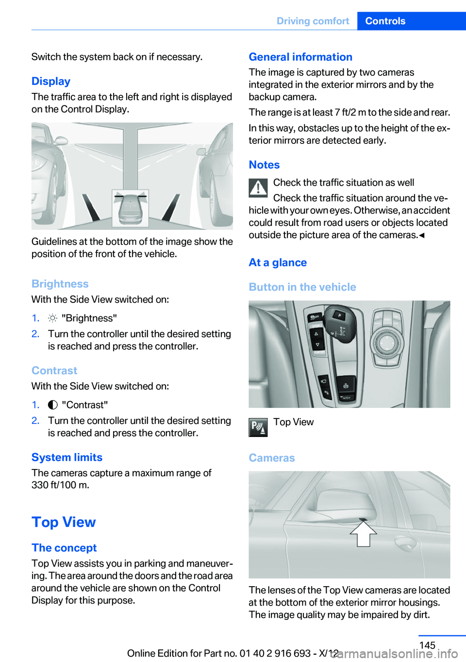
The traffic area to the left and right is displayed
on the Control Display.
Guidelines at the bottom of the image show the
position of the front of the vehicle.
Brightness
With the Side View switched on:
1. "Brightness"2.Turn the controller until the desired setting
is reached and press the controller.
Contrast
With the Side View switched on:
1. "Contrast"2.Turn the controller until the desired setting
is reached and press the controller.
System limits
The cameras capture a maximum range of
330 ft/100 m.
Top View
The concept
Top View assists you in parking and maneuver‐
ing. The area around the doors and the road area
around the vehicle are shown on the Control
Display for this purpose.
General information
The image is captured by two cameras
integrated in the exterior mirrors and by the
backup camera.
The range is at least 7 ft/2 m to the side and rear.
In this way, obstacles up to the height of the ex‐
terior mirrors are detected early.
Notes Check the traffic situation as well
Check the traffic situation around the ve‐
hicle with your own eyes. Otherwise, an accident
could result from road users or objects located
outside the picture area of the cameras.◀
At a glance
Button in the vehicle
Top View
Cameras
The lenses of the Top View cameras are located
at the bottom of the exterior mirror housings.
The image quality may be impaired by dirt.
Seite 145Driving comfortControls145
Online Edition for Part no. 01 40 2 916 693 - X/12
Page 147 of 243
The pathway line is dependent on the cur‐
rent steering angle and is continuously ad‐
justed with the steering wheel movement.
"Parking aid lines"
Turning circle and pathway lines are displayed.
System limits
Top View cannot be used in the following situa‐
tions:
▷With a door open.▷With the trunk lid open.▷With an exterior mirror folded in.▷In poor light.
A Check Control message is displayed in some
of these situations.
Parking assistant
The concept
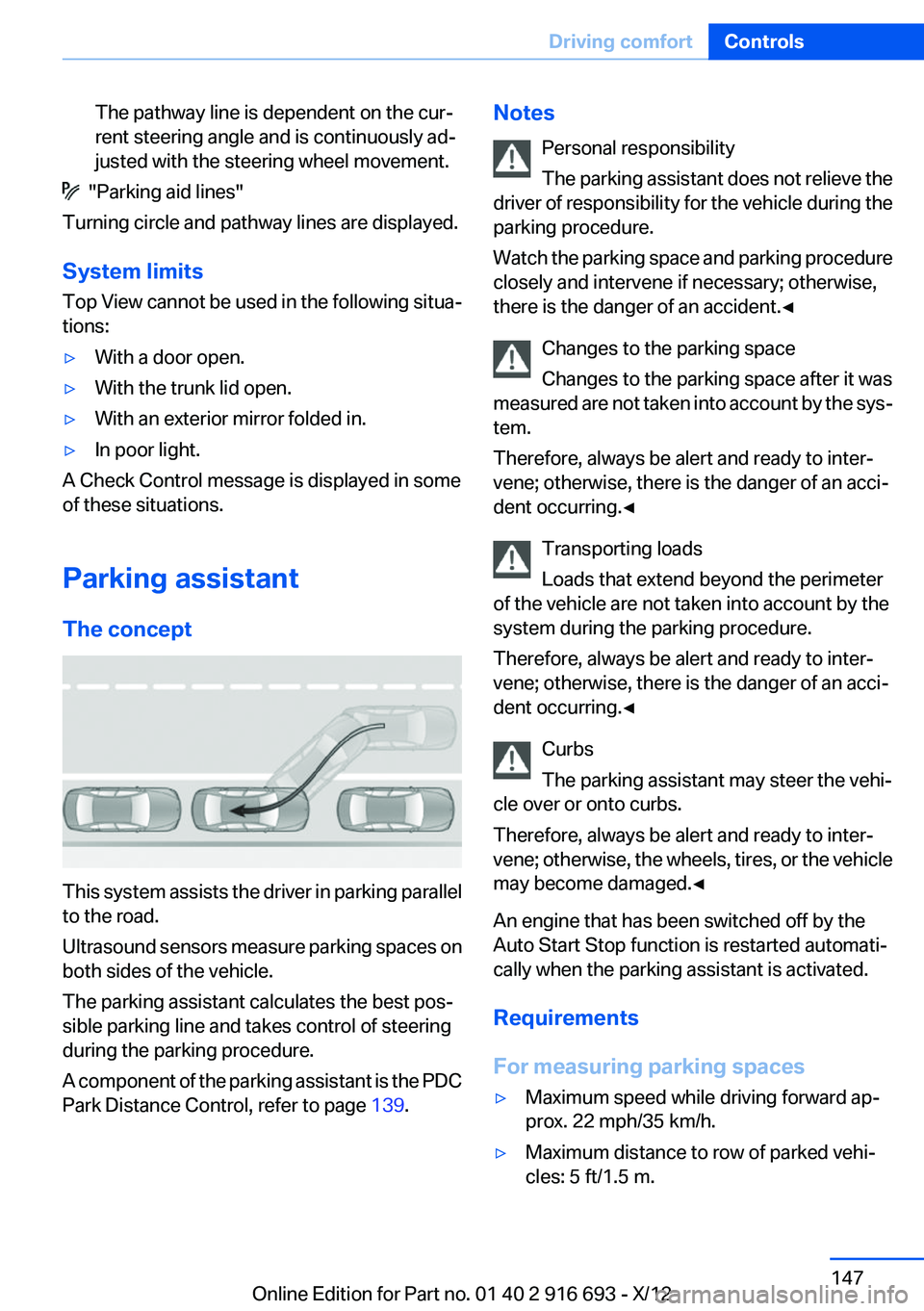
This system assists the driver in parking parallel
to the road.
Ultrasound sensors measure parking spaces on
both sides of the vehicle.
The parking assistant calculates the best pos‐
sible parking line and takes control of steering
during the parking procedure.
A component of the parking assistant is the PDC
Park Distance Control, refer to page 139.
Notes
Personal responsibility
The parking assistant does not relieve the
driver of responsibility for the vehicle during the
parking procedure.
Watch the parking space and parking procedure
closely and intervene if necessary; otherwise,
there is the danger of an accident.◀
Changes to the parking space
Changes to the parking space after it was
measured are not taken into account by the sys‐
tem.
Therefore, always be alert and ready to inter‐
vene; otherwise, there is the danger of an acci‐
dent occurring.◀
Transporting loads
Loads that extend beyond the perimeter
of the vehicle are not taken into account by the
system during the parking procedure.
Therefore, always be alert and ready to inter‐
vene; otherwise, there is the danger of an acci‐
dent occurring.◀
Curbs
The parking assistant may steer the vehi‐
cle over or onto curbs.
Therefore, always be alert and ready to inter‐
vene; otherwise, the wheels, tires, or the vehicle
may become damaged.◀
An engine that has been switched off by the
Auto Start Stop function is restarted automati‐
cally when the parking assistant is activated.
Requirements
For measuring parking spaces▷Maximum speed while driving forward ap‐
prox. 22 mph/35 km/h.▷Maximum distance to row of parked vehi‐
cles: 5 ft/1.5 m.Seite 147Driving comfortControls147
Online Edition for Part no. 01 40 2 916 693 - X/12
Page 148 of 243
▷When parking in parking spaces on the driv‐
er's side, the corresponding turn signal must
be set.
Suitable parking space
▷Gap between two objects with a minimum
length of approx. 5 ft/1.5 m.▷Minimum length of the gap: own vehicle's
length plus approx 4 ft/1.2 m.▷Minimum depth: approx. 5 ft/1.5 m.
For parking procedure
Closed doors.
At a glance
Button in the vehicle
Parking assistant
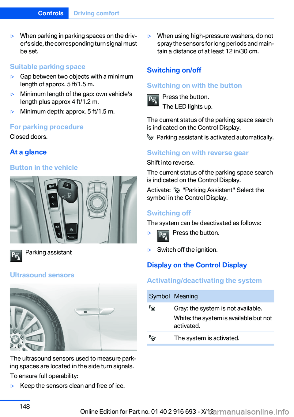
Ultrasound sensors
The ultrasound sensors used to measure park‐
ing spaces are located in the side turn signals.
To ensure full operability:
▷Keep the sensors clean and free of ice.▷When using high-pressure washers, do not
spray the sensors for long periods and main‐
tain a distance of at least 12 in/30 cm.
Switching on/off
Switching on with the button Press the button.
The LED lights up.
The current status of the parking space search
is indicated on the Control Display.
Parking assistant is activated automatically.
Switching on with reverse gear
Shift into reverse.
The current status of the parking space search
is indicated on the Control Display.
Activate:
"Parking Assistant" Select the
symbol in the Control Display.
Switching off
The system can be deactivated as follows:
▷Press the button.▷Switch off the ignition.
Display on the Control Display
Activating/deactivating the system
SymbolMeaning Gray: the system is not available.
White: the system is available but not
activated. The system is activated.Seite 148ControlsDriving comfort148
Online Edition for Part no. 01 40 2 916 693 - X/12
Page 149 of 243
Without Professional navigation
system or TV: system status
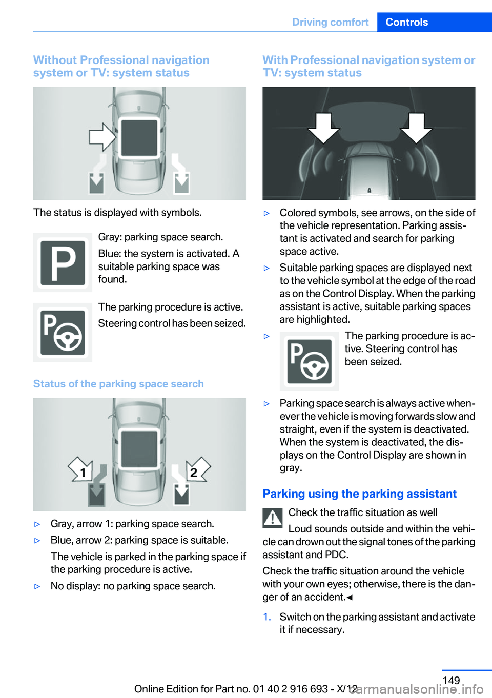
The status is displayed with symbols.
Gray: parking space search.
Blue: the system is activated. A
suitable parking space was
found.
The parking procedure is active.
Steering control has been seized.
Status of the parking space search
▷Gray, arrow 1: parking space search.▷Blue, arrow 2: parking space is suitable.
The vehicle is parked in the parking space if
the parking procedure is active.▷No display: no parking space search.With Professional navigation system or
TV: system status▷Colored symbols, see arrows, on the side of
the vehicle representation. Parking assis‐
tant is activated and search for parking
space active.▷Suitable parking spaces are displayed next
to the vehicle symbol at the edge of the road
as on the Control Display. When the parking
assistant is active, suitable parking spaces
are highlighted.▷The parking procedure is ac‐
tive. Steering control has
been seized.▷Parking space search is always active when‐
ever the vehicle is moving forwards slow and
straight, even if the system is deactivated.
When the system is deactivated, the dis‐
plays on the Control Display are shown in
gray.
Parking using the parking assistant
Check the traffic situation as well
Loud sounds outside and within the vehi‐
cle can drown out the signal tones of the parking
assistant and PDC.
Check the traffic situation around the vehicle
with your own eyes; otherwise, there is the dan‐
ger of an accident.◀
1.Switch on the parking assistant and activate
it if necessary.Seite 149Driving comfortControls149
Online Edition for Part no. 01 40 2 916 693 - X/12
Page 150 of 243
The status of the parking space search is in‐
dicated on the Control Display.2.Follow the instructions on the Control Dis‐
play.
To achieve the best possible parking posi‐
tion, wait for the automatic steering wheel
movement after the gear change when the
vehicle is stationary.
The end of the parking procedure is indi‐
cated on the Control Display.3.Adjust the parking position yourself if nec‐
essary.
Interrupting manually
The parking assistant can be interrupted at any
time:
▷ " Parking Assistant" Select the symbol on
the Control Display.▷Press the button.
Interrupting automatically
The system is interrupted automatically in the
following situations:
▷If the driver grasps the steering wheel or if
he takes over steering.▷If a gear is selected that does not match the
instruction on the Control Display.▷If a turn signal is activated in the opposite
direction to the desired side for parking.▷If the vehicle speed exceeds approx.
6 mph/10 km/h.▷On snow-covered or slippery road surfaces
if necessary.▷If doors are open.▷If the Park Distance Control PDC displays
clearances that are too small.▷If a maximum number of parking attempts or
the time taken for parking is exceeded.
A Check Control message is displayed.
Continuing
An interrupted parking procedure can be con‐
tinued if necessary.
Follow the instructions on the Control Display to
do this.
System limits
No parking assistance
The parking assistant does not offer assistance
in the following situations:▷In tight curves.
Functional limitations
The system may not be fully functional in the
following situations:
▷When sensors are dirty or iced over.▷In heavy fog, rain or snowfall.▷On bumpy road surfaces such as gravel
roads.▷When leaves or snow has collected in the
parking space.
Limits of ultrasonic measurement
The detection of objects can reach the physical
limits of ultrasonic measurement, e.g. in the fol‐
lowing circumstances:
▷With tow bars and trailer hitches.▷With thin or wedge-shaped objects.▷With elevated, protruding objects such as
ledges or cargo.▷With objects with corners and sharp edges.▷With objects with a fine surface structure,
such as fences.
Low objects already displayed, e.g., curbs, can
move into the blind area of the sensors before or
after a continuous tone sounds.
High, protruding objects such as ledges may not
be detected.
The parking assistant may identify parking
spaces that are not suitable for parking.
Seite 150ControlsDriving comfort150
Online Edition for Part no. 01 40 2 916 693 - X/12
Page 151 of 243
Malfunction
A Check Control message is displayed.
The parking assistant failed. Have the system
checked.
Head-up Display
The concept
This system projects important information into
the driver's field of vision, e.g., the speed.
In this way, the driver can get information with‐
out averting his or her eyes from the road.
Display visibility
The visibility of the displays in the Head-up Dis‐
play is influenced by:
▷Certain sitting positions.▷Objects on the cover of the Head-up Dis‐
play.▷Sunglasses with certain polarization filters.▷Wet roads.▷Unfavorable light conditions.
If the image is distorted, check the basic set‐
tings.
Switching on/off
Press the button.
Display
Overview
▷Speed.▷Navigation system.▷Check Control messages.▷Collision warning.▷Speed limit detection.▷Cruise control.▷Distance information.
Some of this information is only displayed briefly
as needed.
Selecting displays in the Head-up
Display
1."Settings"2."Head-Up Display"3."Displayed information"4.Select the desired displays in the Head-up
Display.
The settings are stored for the remote control
currently in use.
Setting the brightness
The brightness is automatically adjusted to the
ambient light.
Seite 151Driving comfortControls151
Online Edition for Part no. 01 40 2 916 693 - X/12
Page 176 of 243
Do not place additional floor mats over existing
mats or other objects.
Only use floor mats that have been approved for
the vehicle and can be properly fixed in place.
Ensure that the floor mats are securely fastened
again after they were removed for cleaning, for
example.◀
Driving in wet conditions
When roads are wet or there is heavy rain, briefly
exert gentle pressure on the brake pedal every
few miles.
Ensure that this action does not endanger other
road users.
The heat generated in this process helps dry the
brake discs and pads.
In this way braking efficiency will be available
when you need it.
Hills
Drive long or steep downhill gradients in the gear
in which the least braking is required. Otherwise,
the brake system may overheat, resulting in a
reduction in the brake system efficiency.
You can increase the engine's braking effect by
shifting down, going all the way to first gear, if
necessary.
Avoid load on the brakes
Avoid placing excessive load on the brake
system. Light but consistent brake pressure can
lead to high temperatures, brake wear and pos‐
sibly even brake failure.◀
Do not drive in neutral
Do not drive in neutral or with the engine
stopped, as doing so disables engine braking. In
addition, steering and brake assist is unavailable
with the engine stopped.◀
Brake disc corrosion
Corrosion on the brake discs and contamination
on the brake pads are furthered by:▷Low mileage.▷Extended periods when the vehicle is not
used at all.▷Infrequent use of the brakes.
Corrosion occurs when the minimum pressure
that must be exerted by the pads during brake
applications to clean the discs is not reached.
Should corrosion form on the brake discs, the
brakes will tend to respond with a pulsating ef‐
fect that generally cannot be corrected.
Condensation under the parked vehicle
When using the automatic climate control, con‐
densation water develops that exits underneath
the vehicle.
Traces of water under the vehicle like this are
normal.
Seite 176Driving tipsThings to remember when driving176
Online Edition for Part no. 01 40 2 916 693 - X/12
Page 219 of 243
Do not touch live parts
To avoid the risk of potentially fatal injury,
always avoid all contact with electrical compo‐
nents while the engine is running.◀
Preparation1.Check whether the battery of the other ve‐
hicle has a voltage of 12 volts. This informa‐
tion can be found on the battery.2.Switch off the engine of the assisting vehi‐
cle.3.Switch off any electronic systems/power
consumers in both vehicles.
Bodywork contact between vehicles
Make sure that there is no contact be‐
tween the bodywork of the two vehicles; other‐
wise, there is the danger of short circuits.◀
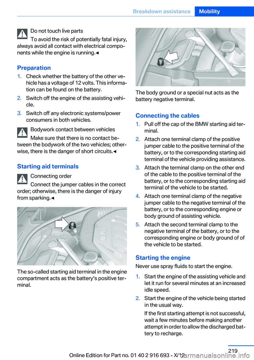
Starting aid terminals Connecting order
Connect the jumper cables in the correct
order; otherwise, there is the danger of injury
from sparking.◀
The so-called starting aid terminal in the engine
compartment acts as the battery's positive ter‐
minal.
The body ground or a special nut acts as the
battery negative terminal.
Connecting the cables
1.Pull off the cap of the BMW starting aid ter‐
minal.2.Attach one terminal clamp of the positive
jumper cable to the positive terminal of the
battery, or to the corresponding starting aid
terminal of the vehicle providing assistance.3.Attach the terminal clamp on the other end
of the cable to the positive terminal of the
battery, or to the corresponding starting aid
terminal of the vehicle to be started.4.Attach one terminal clamp of the negative
jumper cable to the negative terminal of the
battery, or to the corresponding engine or
body ground of assisting vehicle.5.Attach the second terminal clamp to the
negative terminal of the battery, or to the
corresponding engine or body ground of of
the vehicle to be started.
Starting the engine
Never use spray fluids to start the engine.
1.Start the engine of the assisting vehicle and
let it run for several minutes at an increased
idle speed.2.Start the engine of the vehicle being started
in the usual way.
If the first starting attempt is not successful,
wait a few minutes before making another
attempt in order to allow the discharged bat‐
tery to recharge.Seite 219Breakdown assistanceMobility219
Online Edition for Part no. 01 40 2 916 693 - X/12
Page 234 of 243
Condensation under the vehi‐cle 176
Condition Based Service CBS 208
Configure driving mode 129
Confirmation signal 35
ConnectedDrive, see user's manual for Navigation, Enter‐
tainment and Communica‐
tion
Control Display 16
Control Display, settings 93
Controller 16
Control systems, driving sta‐ bility 123
Convenient opening 34
Coolant 207
Coolant temperature 86
Cooler 165
Cooling function 156
Cooling, maximum 155
Cooling system 207
Corrosion on brake discs 176
Cruise control 137
Cruise control, active with Stop & Go 131
Cruising range 87
Cupholder 170
Curb weight 229
Current fuel consumption 87
D
Damage, tires 198
Damping control, dy‐ namic 126
Data, technical 228
Date 87
Daytime running lights 96
Defrosting, refer to Windows, defrosting 155
Dehumidifying, air 156
Destination distance 91
Digital clock 86
Dimensions 228
Dimmable exterior mirrors 60 Dimmable interior rearview
mirror 60
Direction indicator, refer to Turn signals 73
Display in windshield 151
Display lighting, refer to Instru‐ ment lighting 98
Displays 79, 80
Displays, cleaning 225
Disposal, vehicle battery 216
Distance control, refer to PDC 139
Distance information 152
Distance, selecting for ACC 133
Distance to destination 91
Divided screen view, split screen 20
Door lock, refer to Remote control 30
Doors, Automatic Soft Clos‐ ing 37
Downhill control 125
Drive-off assistant 123
Drive-off assistant, refer to DSC 123
Driving Dynamics Control 127
Driving instructions, breaking in 174
Driving mode 127
Driving notes, general 174
Driving stability control sys‐ tems 123
Driving tips 174
DSC Dynamic Stability Con‐ trol 123
DTC driving dynamics 124
DTC Dynamic Traction Con‐ trol 124
Dynamic Damping Con‐ trol 126
Dynamic Drive 126
Dynamic Light Spot 213
Dynamic Light Spot, refer to Night Vision 114 Dynamic Stability Control
DSC 123
Dynamic Traction Control DTC 124
E
ECO PRO 181
ECO PRO, bonus range 182
ECO PRO display 181
ECO PRO driving mode 181
ECO PRO mode 181
ECO PRO Tip - driving instruc‐ tion 183
EfficientDynamics 183
Electronic displays, instru‐ ment cluster 80
Electronic Stability Program ESP, refer to DSC 123
Emergency detection, remote control 31
Emergency release, door lock 36
Emergency release, fuel filler flap 188
Emergency release, parking brake 70
Emergency Request 217
Emergency service, refer to Roadside Assistance 218
Emergency start function, en‐ gine start 31
Emergency unlocking, trunk lid 40
Energy Control 87
Energy recovery 87
Engine, automatic Start/Stop function 68
Engine, automatic switch- off 68
Engine compartment 202
Engine compartment, working in 202
Engine coolant 207
Engine idling when driving, coasting 184 Seite 234ReferenceEverything from A to Z234
Online Edition for Part no. 01 40 2 916 693 - X/12
Page 237 of 243
Locking/unlocking via doorlock 36
Locking/unlocking with re‐ mote control 34
Locking, automatic 37
Locking, central 33
Locking via trunk lid 38
Lock, power window 44
Locks, doors, and win‐ dows 65
Low beams 95
Low beams, automatic, refer to High-beam Assistant 97
Lower back support 49
Lug bolt lock 215
Luggage rack, refer to Roof- mounted luggage rack 178
Lumbar support 49
M
Maintenance 208
Maintenance require‐ ments 208
Maintenance, service require‐ ments 87
Maintenance system, BMW 208
Malfunction displays, refer to Check Control 83
Malfunction, self-leveling sus‐ pension 127
Manual air distribution 155
Manual air flow 155
Manual brake, refer to Parking brake 70
Manual mode, transmis‐ sion 78
Manual operation, backup camera 142
Manual operation, door lock 36
Manual operation, exterior mir‐ rors 59
Manual operation, fuel filler flap 188 Manual operation, Park Dis‐
tance Control PDC 140
Manual operation, parking brake 70
Manual operation, Side View 144
Manual operation, Top View 146
Manual operation, trunk lid 38
Marking on approved tires 199
Marking, run-flat tires 200
Massage seat, front 50
Massage seat, rear 53
Master key, refer to Remote control 30
Maximum cooling 155
Maximum speed, display 88
Maximum speed, winter tires 199
Measure, units of 94
Medical kit 218
Memory for seat, mirrors, steering wheel 58
Menu, EfficientDynamics 183
Menu in instrument cluster 90
Menus, operating, iDrive 16
Menus, refer to iDrive operat‐ ing concept 17
Messages, refer to Check Control 83
Microfilter 157
Minimum tread, tires 198
Mirror 59
Mirror memory 58
Mobile communication devi‐ ces in the vehicle 175
Modifications, technical, refer to Safety 7
Moisture in headlamp 211
Monitor, refer to Control Dis‐ play 16
Mounting of child restraint fix‐ ing systems 62
Multifunctional instrument display 80 Multifunction steering wheel,
buttons 12
N
Navigation, see user's manual for Navigation, Entertain‐
ment and Communication
Neck restraints, front, refer to Head restraints 55
Neck restraints, rear, refer to Head restraints 56
New wheels and tires 198
Night vision device, refer to Night Vision 114
Night Vision with pedestrian detection 114
No Passing Information 88
Nylon rope for tow-starting/ towing 220
O
OBD Onboard Diagnos‐ tics 209
Object detection, refer to Night Vision 114
Obstacle marking, backup camera 143
Octane rating, refer to Gaso‐ line quality 190
Odometer 86
Office, see user's manual for Navigation, Entertainment
and Communication
Oil 204
Oil, adding 205
Oil additives 205
Oil change 205
Oil change interval, service re‐ quirements 87
Oil filler neck 205
Oil types, alternative 205
Oil types, approved 205
Old batteries, disposal 216 Seite 237Everything from A to ZReference237
Online Edition for Part no. 01 40 2 916 693 - X/12