Mag BMW 750LI XDRIVE 2013 Owners Manual
[x] Cancel search | Manufacturer: BMW, Model Year: 2013, Model line: 750LI XDRIVE, Model: BMW 750LI XDRIVE 2013Pages: 243, PDF Size: 5.37 MB
Page 6 of 243
NotesUsing this Owner's Manual
The fastest way to find information on a partic‐
ular topic is by using the index.
An initial overview of the vehicle is provided in
the first chapter.
Updates made after the editorial
deadline
Any updates made after the editorial deadline for
the Owner's Manuals are located in the appen‐
dix of the printed quick reference for the vehicle.
User's manual for Navigation,
Entertainment, Communication
The topics of Navigation, Entertainment, Com‐
munication and the short commands of the
voice activation system are described in a sep‐
arate user's manual, which is also included with
the onboard literature.
Additional sources of information
Should you have any questions, your service
center will be glad to advise you at any time.
Information on BMW, e.g., on technology, is
available on the Internet: bmwusa.com.
Symbols
Indicates precautions that must be followed
precisely in order to avoid the possibility of per‐
sonal injury and serious damage to the vehicle.
◄ Marks the end of a specific item of informa‐
tion.
"..." Identifies Control Display texts used to se‐
lect individual functions.
›...‹ Verbal instructions to use with the voice ac‐
tivation system.
››...‹‹ Identifies the answers generated by the
voice activation system.
Refers to measures that can be taken to help
protect the environment.
Symbols on vehicle components
Indicates that you should consult the rele‐
vant section of this Owner's Manual for infor‐
mation on a particular part or assembly.
Vehicle equipment
This Owner's Manual describes all models and
all standard, country-specific and optional
equipment that is offered in the model series.
Therefore, in this Owner's Manual, equipment is
also described and illustrated that is not availa‐
ble in your vehicle, e.g. because of the selected
optional equipment or the country-specific var‐
iants.
This also applies for safety-related functions
and systems.
For options and equipment not described in this
Owner's Manual, please refer to the Supple‐
mentary Owner's Manuals.
On right-hand drive vehicles, some controls are
arranged differently than shown in the illustra‐
tions.
Status of the Owner's Manual
The manufacturer of your vehicle pursues a pol‐
icy of constant development that is conceived
to ensure that our vehicles continue to embody
the highest quality and safety standards. In rare
cases, therefore, the features described in this
Owner's Manual may differ from those in your
vehicle.
Seite 6Notes6
Online Edition for Part no. 01 40 2 916 693 - X/12
Page 7 of 243
Updates made after the editorial
deadline
Any updates made after the editorial deadline for
the Owner's Manuals are located in the appen‐
dix of the printed quick reference for the vehicle.
For your own safety
Maintenance and repairs
Advanced technology, e.g., the use of modern
materials and high-performance electronics, re‐
quires suitable maintenance and repair meth‐
ods.
Therefore, have this work performed only by a
BMW center or a workshop that works accord‐
ing to BMW repair procedures with appropri‐
ately trained personnel.
If this work is not carried out properly, there is
the danger of subsequent damage and related
safety hazards.
Parts and Accessories
For your own safety, use genuine parts and ac‐
cessories approved by BMW. When you pur‐
chase accessories tested and approved by
BMW and Genuine BMW Parts, you simultane‐
ously acquire the assurance that they have been
thoroughly tested by BMW to ensure optimum
performance when installed on your vehicle.
BMW warrants these parts to be free from de‐
fects in material and workmanship. BMW will not
accept any liability for damage resulting from in‐
stallation of parts and accessories not approved
by BMW. BMW cannot test every product made
by other manufacturers to verify if it can be used
on a BMW safely and without risk to either the
vehicle, its operation, or its occupants. Genuine
BMW Parts, BMW Accessories and other prod‐
ucts approved by BMW, together with profes‐
sional advice on using these items, are available
from all BMW centers. Installation and operation
of non-BMW approved accessories such as
alarms, radios, amplifiers, radar detectors,
wheels, suspension components, brake dustshields, telephones, including operation of any
mobile phone from within the vehicle without
using an externally mounted antenna, or trans‐
ceiver equipment, for instance, CBs, walkie-
talkies, ham radios or similar accessories, may
cause extensive damage to the vehicle, com‐
promise its safety, interfere with the vehicle's
electrical system or affect the validity of the
BMW Limited Warranty. See your BMW center
for additional information. Maintenance, re‐
placement, or repair of the emission control de‐
vices and systems may be performed by any au‐
tomotive repair establishment or individual
using any certified automotive part.
California Proposition 65 Warning
California laws require us to state the following
warning:
Engine exhaust and a wide variety of automobile
components and parts, including components
found in the interior furnishings in a vehicle, con‐
tain or emit chemicals known to the State of Cal‐
ifornia to cause cancer and birth defects and re‐
productive harm. In addition, certain fluids
contained in vehicles and certain products of
component wear contain or emit chemicals
known to the State of California to cause cancer
and birth defects or other reproductive harm.
Battery posts, terminals and related accessories
contain lead and lead compounds. Wash your
hands after handling. Used engine oil contains
chemicals that have caused cancer in laboratory
animals. Always protect your skin by washing
thoroughly with soap and water.
Service and warranty
We recommend that you read this publication
thoroughly. Your vehicle is covered by the fol‐
lowing warranties:▷New Vehicle Limited Warranty.▷Rust Perforation Limited Warranty.▷Federal Emissions System Defect Warranty.▷Federal Emissions Performance Warranty.Seite 7Notes7
Online Edition for Part no. 01 40 2 916 693 - X/12
Page 8 of 243
▷California Emission Control System Limited
Warranty.
Detailed information about these warranties is
listed in the Service and Warranty Information
Booklet for US models or in the Warranty and
Service Guide Booklet for Canadian models.
Your vehicle has been specifically adapted and
designed to meet the particular operating con‐
ditions and homologation requirements in your
country and continental region in order to deliver
the full driving pleasure while the vehicle is op‐
erated under those conditions. If you wish to op‐
erate your vehicle in another country or region,
you may be required to adapt your vehicle to
meet different prevailing operating conditions
and homologation requirements. You should
also be aware of any applicable warranty limita‐
tions or exclusions for such country or region. In
such case, please contact Customer Relations
for further information.
Maintenance
Maintain the vehicle regularly to sustain the road
safety, operational reliability and the New Vehi‐
cle Limited Warranty.
Specifications for required maintenance meas‐
ures:
▷BMW Maintenance system▷Service and Warranty Information Booklet
for US models▷Warranty and Service Guide Booklet for
Canadian models
If the vehicle is not maintained according to
these specifications, this could result in serious
damage to the vehicle. Such damage is not cov‐
ered by the BMW New Vehicle Limited War‐
ranty.
Data memory
Many electronic components on your vehicle
are equipped with data memories that tempo‐
rarily or permanently store technical information
about the condition of the vehicle, events and
faults. This technical information generally
documents the state of a component, a module,
a system or the environment:▷Operating states of system components, fill
levels for instance.▷Status messages for the vehicle and from its
individual components, e.g., wheel rotation
speed/ vehicle speed, deceleration, trans‐
verse acceleration.▷Malfunctions and faults in important system
components, e.g., lights and brakes.▷Responses by the vehicle to special situa‐
tions, e.g., deployment of an airbag, engage‐
ment of stability control systems.▷Ambient conditions, such as temperature.
This data is purely technical in nature and is used
to detect and correct faults and to optimize ve‐
hicle functions. Motion profiles over routes trav‐
eled cannot be created from this data. When
service offerings are used, e.g., repair services,
service processes, warranty claims, quality as‐
surance, this technical information can be read
out from the event and fault memories by the
service personnel, including the manufacturer,
using special diagnostic tools. You can obtain
further information there if it is needed. After a
fault is corrected, the information in the fault
memory is deleted or overwritten on a continu‐
ous basis.
When the vehicle is in use, situations are con‐
ceivable in which it might be possible to asso‐
ciate this technical data with individuals if it is
combined with other information, e.g., an acci‐
dent report, damage to the vehicle, eye witness
accounts — possibly with the assistance of an
expert.
Additional functions that are contractually
agreed with the customer, such as vehicle lo‐
cating in an emergency, enable certain vehicle
data to be transmitted from the vehicle.
Seite 8Notes8
Online Edition for Part no. 01 40 2 916 693 - X/12
Page 16 of 243
iDriveVehicle equipment
All standard, country-specific and optional
equipment that is offered in the model series is
described in this chapter. Therefore, equipment
is also described that is not available in a vehicle,
e. g., because of the selected optional equip‐
ment or country variant. This also applies for
safety-related functions and systems.
The concept
The iDrive combines the functions of a multitude
of switches. Thus, these functions can be oper‐
ated from a central location.
Using the iDrive during a trip
To avoid becoming distracted and posing
an unnecessary hazard to your vehicle's occu‐
pants and to other road users, never attempt to
use the controls or enter information unless traf‐
fic and road conditions allow this.◀
Controls at a glance
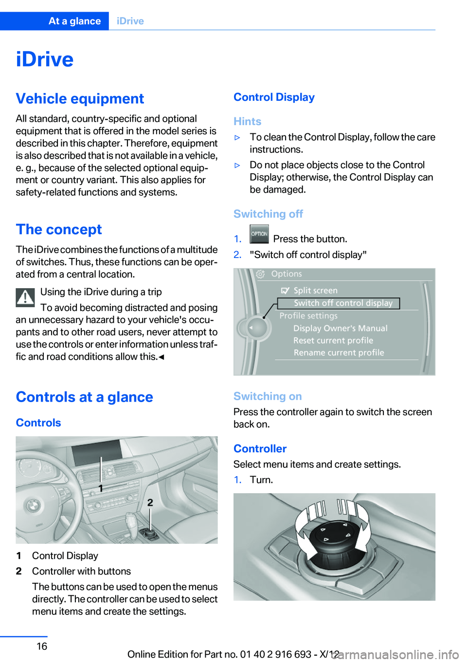
Controls1Control Display2Controller with buttons
The buttons can be used to open the menus
directly. The controller can be used to select
menu items and create the settings.Control Display
Hints▷To clean the Control Display, follow the care
instructions.▷Do not place objects close to the Control
Display; otherwise, the Control Display can
be damaged.
Switching off
1. Press the button.2."Switch off control display"
Switching on
Press the controller again to switch the screen
back on.
Controller
Select menu items and create settings.
1.Turn.Seite 16At a glanceiDrive16
Online Edition for Part no. 01 40 2 916 693 - X/12
Page 35 of 243
Panic mode
You can trigger the alarm system if you find
yourself in a dangerous situation.
Press the button on the remote control
for at least 3 seconds.
To switch off the alarm: press any button.
Switching on the headlamp courtesy
delay feature
Briefly press the button on the remote
control.
The duration can be set in the Control Display.
Opening the trunk lid Press the button on the remote control
for approx. 1 second.
The trunk lid opens, regardless of whether it was
previously locked or unlocked.
During opening, the trunk lid pivots back and up.
Ensure that adequate clearance is available be‐
fore opening.
In some vehicle equipment variants, the trunk lid
can only be opened using the remote control if
the vehicle has been unlocked.
Do not place the remote control in the
cargo area
Take the remote control with you and do not
leave it in the cargo area; otherwise, the remote
control is locked inside the vehicle when the
trunk lid is closed.◀
The trunk lid is locked again as soon as it is
pushed closed.
Confirmation signals from the vehicle1."Settings"2."Doors/key"3.Deactivate or activate the desired confirma‐
tion signals.▷"Acoustic sig. lock/unlock"▷"Flash when lock/unlock"
Retrieving the seat, mirror, and
steering wheel settings
The driver's seat, exterior mirror, and steering
wheel positions selected last are stored for the
currently used remote control.
When the vehicle is unlocked, these positions
are automatically retrieved if this function was
activated.
Pinch hazard when moving back the seat
If this function is used, first make sure that
the footwell behind the driver's seat is empty.
Otherwise, people can be injured or objects
damaged when the seat is moved back.◀
The adjustment procedure is interrupted:
▷When a seat position switch is pressed.▷When a button of the seat, mirror, and steer‐
ing wheel memory is pressed briefly.
Activating the setting
1."Settings"2."Doors/key"3."Last seat position auto."
Malfunction
If the vehicle can no longer be locked or un‐
locked with the remote control, the battery may
be discharged or there may be interference from
external sources such as mobile phones, metal
objects, overhead power lines, transmission
towers, etc.
If this occurs, unlock or lock the vehicle at the
door lock using the integrated key.
For US owners only
The transmitter and receiver units comply with
part 15 of the FCC/Federal Communication
Commission regulations. Operation is governed
by the following:
FCC ID:
▷LX8766S.Seite 35Opening and closingControls35
Online Edition for Part no. 01 40 2 916 693 - X/12
Page 36 of 243
▷LX8766E.▷LX8CAS.▷LX8CAS2.▷MYTCAS4.
Compliance statement:
This device complies with part 15 of the FCC
Rules. Operation is subject to the following two
conditions:
▷This device may not cause harmful interfer‐
ence, and▷this device must accept any interference re‐
ceived, including interference that may
cause undesired operation.
Any unauthorized modifications or changes to
these devices could void the user's authority to
operate this equipment.
Using the door lock
General information
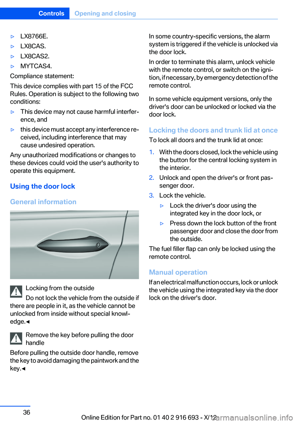
Locking from the outside
Do not lock the vehicle from the outside if
there are people in it, as the vehicle cannot be
unlocked from inside without special knowl‐
edge.◀
Remove the key before pulling the door
handle
Before pulling the outside door handle, remove
the key to avoid damaging the paintwork and the
key.◀
In some country-specific versions, the alarm
system is triggered if the vehicle is unlocked via
the door lock.
In order to terminate this alarm, unlock vehicle
with the remote control, or switch on the igni‐
tion, if necessary, by emergency detection of the
remote control.
In some vehicle equipment versions, only the
driver's door can be unlocked or locked via the
door lock.
Locking the doors and trunk lid at once
To lock all doors and the trunk lid at once:1.With the doors closed, lock the vehicle using
the button for the central locking system in
the interior.2.Unlock and open the driver's or front pas‐
senger door.3.Lock the vehicle.▷Lock the driver's door using the
integrated key in the door lock, or▷Press down the lock button of the front
passenger door and close the door from
the outside.
The fuel filler flap can only be locked using the
remote control.
Manual operation
If an electrical malfunction occurs, lock or unlock
the vehicle using the integrated key via the door
lock on the driver's door.
Seite 36ControlsOpening and closing36
Online Edition for Part no. 01 40 2 916 693 - X/12
Page 55 of 243
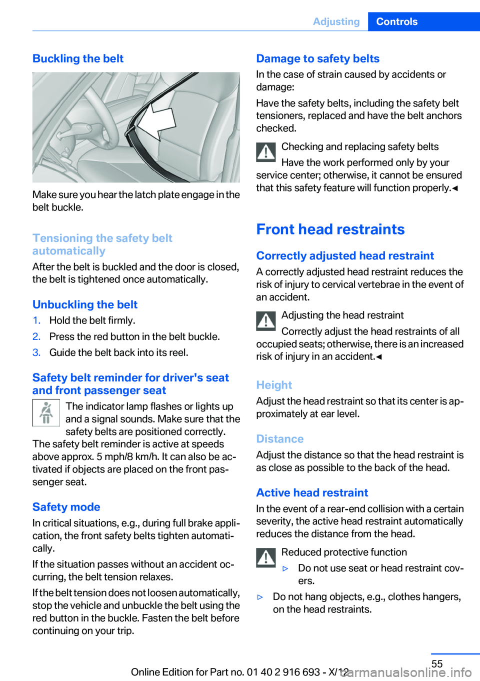
Buckling the belt
Make sure you hear the latch plate engage in the
belt buckle.
Tensioning the safety belt
automatically
After the belt is buckled and the door is closed,
the belt is tightened once automatically.
Unbuckling the belt
1.Hold the belt firmly.2.Press the red button in the belt buckle.3.Guide the belt back into its reel.
Safety belt reminder for driver's seat
and front passenger seat
The indicator lamp flashes or lights up
and a signal sounds. Make sure that the
safety belts are positioned correctly.
The safety belt reminder is active at speeds
above approx. 5 mph/8 km/h. It can also be ac‐
tivated if objects are placed on the front pas‐
senger seat.
Safety mode
In critical situations, e.g., during full brake appli‐
cation, the front safety belts tighten automati‐
cally.
If the situation passes without an accident oc‐
curring, the belt tension relaxes.
If the belt tension does not loosen automatically,
stop the vehicle and unbuckle the belt using the
red button in the buckle. Fasten the belt before
continuing on your trip.
Damage to safety belts
In the case of strain caused by accidents or
damage:
Have the safety belts, including the safety belt
tensioners, replaced and have the belt anchors
checked.
Checking and replacing safety belts
Have the work performed only by your
service center; otherwise, it cannot be ensured
that this safety feature will function properly.◀
Front head restraints
Correctly adjusted head restraint
A correctly adjusted head restraint reduces the
risk of injury to cervical vertebrae in the event of
an accident.
Adjusting the head restraint
Correctly adjust the head restraints of all
occupied seats; otherwise, there is an increased
risk of injury in an accident.◀
Height
Adjust the head restraint so that its center is ap‐
proximately at ear level.
Distance
Adjust the distance so that the head restraint is
as close as possible to the back of the head.
Active head restraint
In the event of a rear-end collision with a certain
severity, the active head restraint automatically
reduces the distance from the head.
Reduced protective function▷Do not use seat or head restraint cov‐
ers.▷Do not hang objects, e.g., clothes hangers,
on the head restraints.Seite 55AdjustingControls55
Online Edition for Part no. 01 40 2 916 693 - X/12
Page 57 of 243
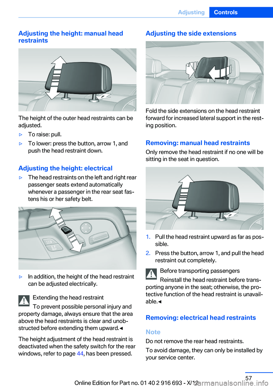
Adjusting the height: manual head
restraints
The height of the outer head restraints can be
adjusted.
▷To raise: pull.▷To lower: press the button, arrow 1, and
push the head restraint down.
Adjusting the height: electrical
▷The head restraints on the left and right rear
passenger seats extend automatically
whenever a passenger in the rear seat fas‐
tens his or her safety belt.▷In addition, the height of the head restraint
can be adjusted electrically.
Extending the head restraint
To prevent possible personal injury and
property damage, always ensure that the area
above the head restraints is clear and unob‐
structed before extending them upward.◀
The height adjustment of the head restraint is
deactivated when the safety switch for the rear
windows, refer to page 44, has been pressed.
Adjusting the side extensions
Fold the side extensions on the head restraint
forward for increased lateral support in the rest‐
ing position.
Removing: manual head restraints
Only remove the head restraint if no one will be
sitting in the seat in question.
1.Pull the head restraint upward as far as pos‐
sible.2.Press the button, arrow 1, and pull the head
restraint out completely.
Before transporting passengers
Reinstall the head restraint before trans‐
porting anyone in the seat; otherwise, the pro‐
tective function of the head restraint is unavail‐
able.◀
Removing: electrical head restraints
Note
Do not remove the rear head restraints.
To avoid damage, they can only be installed by
your service center.
Seite 57AdjustingControls57
Online Edition for Part no. 01 40 2 916 693 - X/12
Page 60 of 243
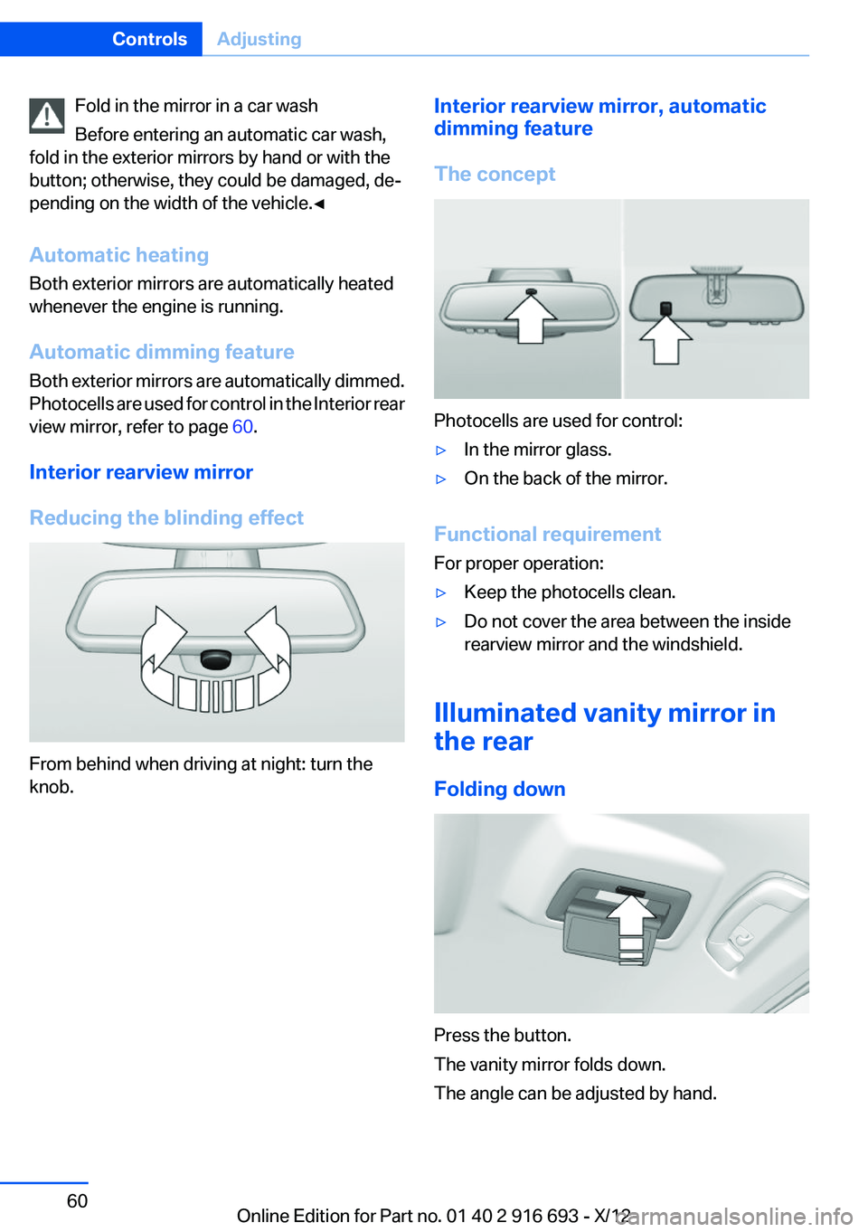
Fold in the mirror in a car wash
Before entering an automatic car wash,
fold in the exterior mirrors by hand or with the
button; otherwise, they could be damaged, de‐
pending on the width of the vehicle.◀
Automatic heating
Both exterior mirrors are automatically heated
whenever the engine is running.
Automatic dimming feature
Both exterior mirrors are automatically dimmed.
Photocells are used for control in the Interior rear
view mirror, refer to page 60.
Interior rearview mirror
Reducing the blinding effect
From behind when driving at night: turn the
knob.
Interior rearview mirror, automatic
dimming feature
The concept
Photocells are used for control:
▷In the mirror glass.▷On the back of the mirror.
Functional requirement
For proper operation:
▷Keep the photocells clean.▷Do not cover the area between the inside
rearview mirror and the windshield.
Illuminated vanity mirror in
the rear
Folding down
Press the button.
The vanity mirror folds down.
The angle can be adjusted by hand.
Seite 60ControlsAdjusting60
Online Edition for Part no. 01 40 2 916 693 - X/12
Page 64 of 243
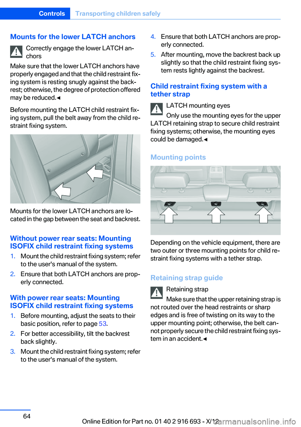
Mounts for the lower LATCH anchorsCorrectly engage the lower LATCH an‐
chors
Make sure that the lower LATCH anchors have
properly engaged and that the child restraint fix‐
ing system is resting snugly against the back‐
rest; otherwise, the degree of protection offered
may be reduced.◀
Before mounting the LATCH child restraint fix‐
ing system, pull the belt away from the child re‐
straint fixing system.
Mounts for the lower LATCH anchors are lo‐
cated in the gap between the seat and backrest.
Without power rear seats: Mounting
ISOFIX child restraint fixing systems
1.Mount the child restraint fixing system; refer
to the user's manual of the system.2.Ensure that both LATCH anchors are prop‐
erly connected.
With power rear seats: Mounting
ISOFIX child restraint fixing systems
1.Before mounting, adjust the seats to their
basic position, refer to page 53.2.For better accessibility, tilt the backrest
back slightly.3.Mount the child restraint fixing system; refer
to the user's manual of the system.4.Ensure that both LATCH anchors are prop‐
erly connected.5.After mounting, move the backrest back up
slightly so that the child restraint fixing sys‐
tem rests lightly against the backrest.
Child restraint fixing system with a
tether strap
LATCH mounting eyes
Only use the mounting eyes for the upper
LATCH retaining strap to secure child restraint
fixing systems; otherwise, the mounting eyes
could be damaged.◀
Mounting points
Depending on the vehicle equipment, there are
two outer or three mounting points for child re‐
straint fixing systems with a tether strap.
Retaining strap guide Retaining strap
Make sure that the upper retaining strap is
not routed over the head restraints or sharp
edges and is free of twisting on its way to the
upper mounting point; otherwise, the belt can‐
not properly secure the child restraint fixing sys‐
tem in an accident.◀
Seite 64ControlsTransporting children safely64
Online Edition for Part no. 01 40 2 916 693 - X/12