light BMW 750LI XDRIVE SEDAN 2011 User Guide
[x] Cancel search | Manufacturer: BMW, Model Year: 2011, Model line: 750LI XDRIVE SEDAN, Model: BMW 750LI XDRIVE SEDAN 2011Pages: 299, PDF Size: 8.49 MB
Page 44 of 299
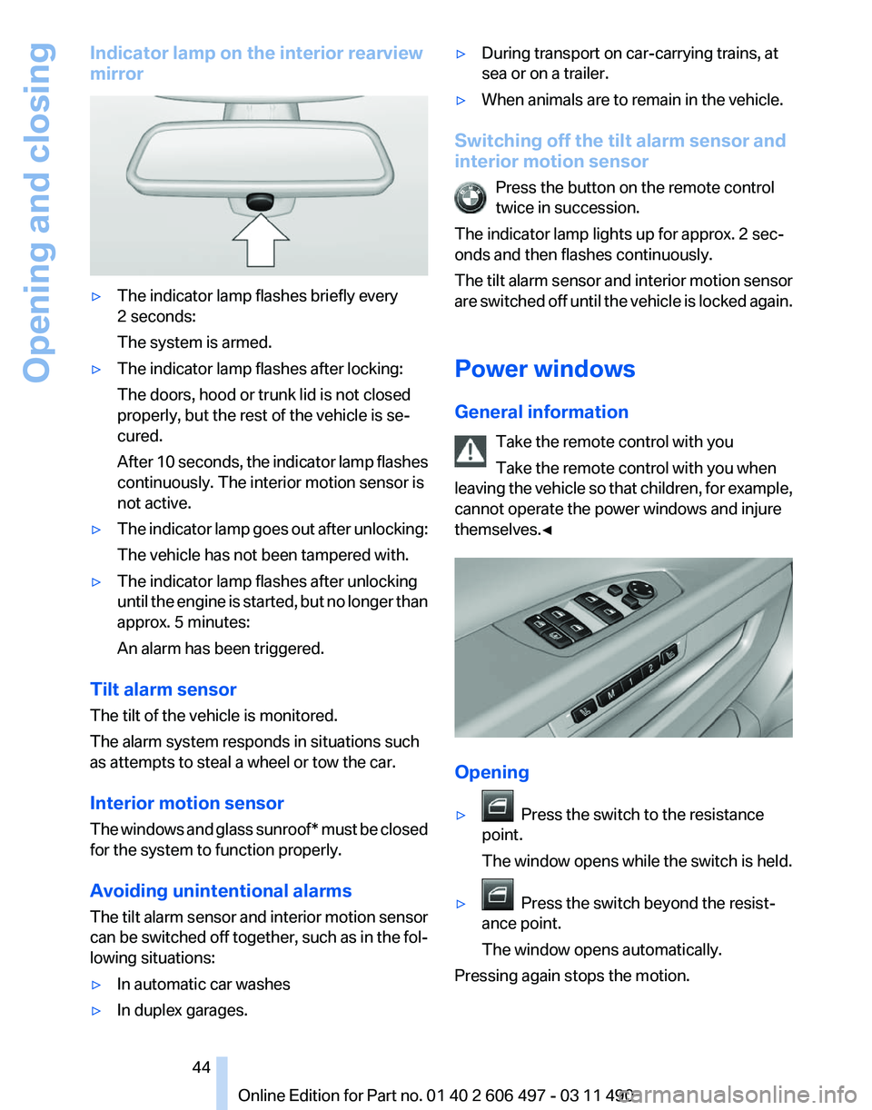
Indicator lamp on the interior rearview
mirror
▷
The indicator lamp flashes briefly every
2 seconds:
The system is armed.
▷ The indicator lamp flashes after locking:
The doors, hood or trunk lid is not closed
properly, but the rest of the vehicle is se‐
cured.
After
10 seconds, the indicator lamp flashes
continuously. The interior motion sensor is
not active.
▷ The indicator lamp goes out after unlocking:
The vehicle has not been tampered with.
▷ The indicator lamp flashes after unlocking
until
the engine is started, but no longer than
approx. 5 minutes:
An alarm has been triggered.
Tilt alarm sensor
The tilt of the vehicle is monitored.
The alarm system responds in situations such
as attempts to steal a wheel or tow the car.
Interior motion sensor
The
windows and glass sunroof* must be closed
for the system to function properly.
Avoiding unintentional alarms
The tilt alarm sensor and interior motion sensor
can be switched off together, such as in the fol‐
lowing situations:
▷ In automatic car washes
▷ In duplex garages. ▷
During transport on car-carrying trains, at
sea or on a trailer.
▷ When animals are to remain in the vehicle.
Switching off the tilt alarm sensor and
interior motion sensor Press the button on the remote control
twice in succession.
The indicator lamp lights up for approx. 2 sec‐
onds and then flashes continuously.
The
tilt alarm sensor and interior motion sensor
are switched off until the vehicle is locked again.
Power windows
General information
Take the remote control with you
Take the remote control with you when
leaving the vehicle so that children, for example,
cannot operate the power windows and injure
themselves.◀ Opening
▷
Press the switch to the resistance
point.
The window opens while the switch is held.
▷ Press the switch beyond the resist‐
ance point.
The window opens automatically.
Pressing again stops the motion. Seite 44
44 Online Edition for Part no. 01 40 2 606 497 - 03 11 490
Opening and closing
Page 45 of 299
Closing
Danger of pinching
Monitor the closing process and make
sure
that the closing path of the window is clear;
otherwise, injuries may result.◀
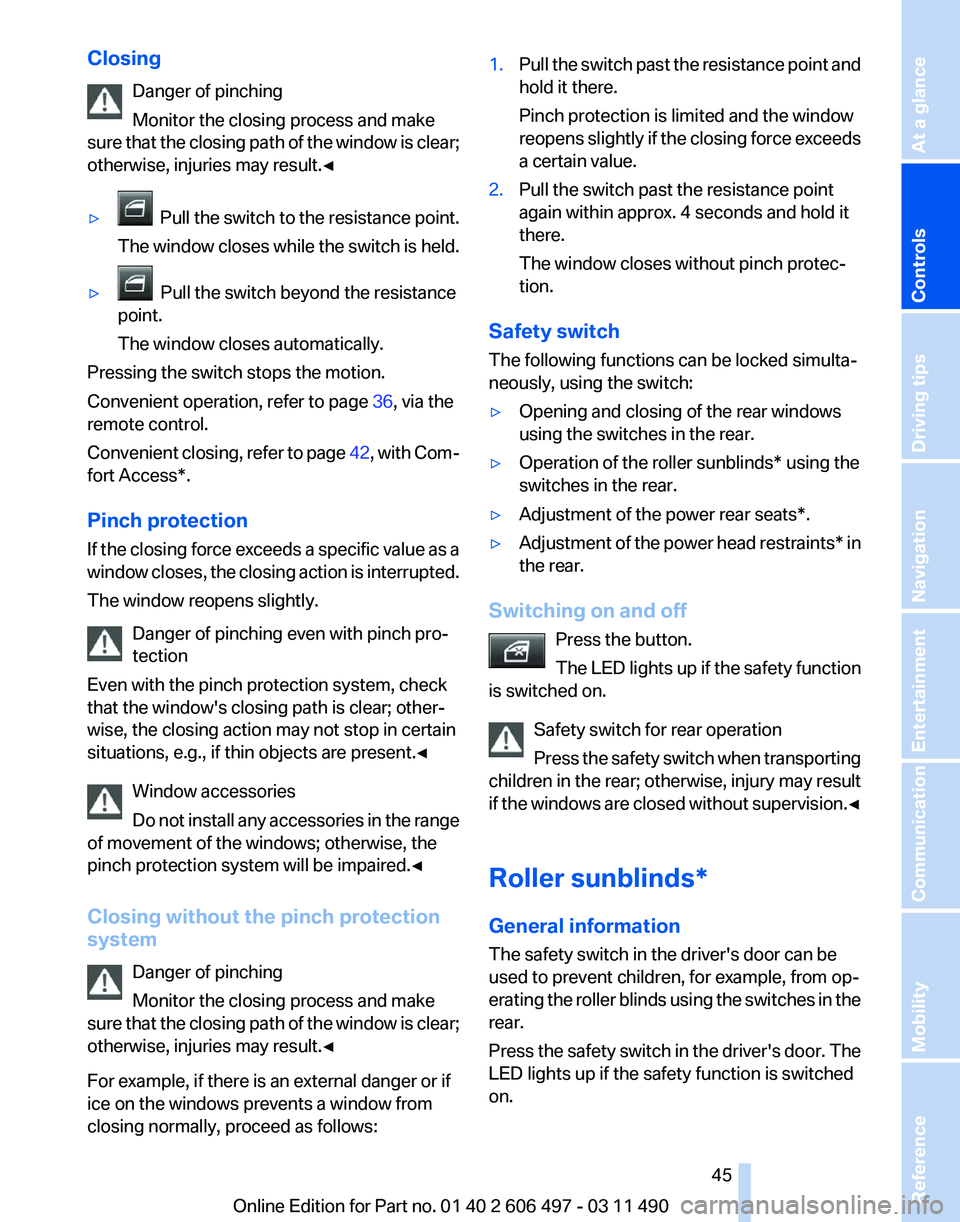
▷ Pull
the switch to the resistance point.
The window closes while the switch is held.
▷ Pull the switch beyond the resistance
point.
The window closes automatically.
Pressing the switch stops the motion.
Convenient operation, refer to page 36, via the
remote control.
Convenient
closing, refer to page 42, with Com‐
fort Access*.
Pinch protection
If the closing force exceeds a specific value as a
window closes, the closing action is interrupted.
The window reopens slightly.
Danger of pinching even with pinch pro‐
tection
Even with the pinch protection system, check
that the window's closing path is clear; other‐
wise, the closing action may not stop in certain
situations, e.g., if thin objects are present.◀
Window accessories
Do not install any accessories in the range
of movement of the windows; otherwise, the
pinch protection system will be impaired.◀
Closing without the pinch protection
system
Danger of pinching
Monitor the closing process and make
sure that the closing path of the window is clear;
otherwise, injuries may result.◀
For example, if there is an external danger or if
ice on the windows prevents a window from
closing normally, proceed as follows: 1.
Pull the switch past the resistance point and
hold it there.
Pinch protection is limited and the window
reopens
slightly if the closing force exceeds
a certain value.
2. Pull the switch past the resistance point
again within approx. 4 seconds and hold it
there.
The window closes without pinch protec‐
tion.
Safety switch
The following functions can be locked simulta‐
neously, using the switch:
▷ Opening and closing of the rear windows
using the switches in the rear.
▷ Operation of the roller sunblinds* using the
switches in the rear.
▷ Adjustment of the power rear seats*.
▷ Adjustment of the power head restraints* in
the rear.
Switching on and off Press the button.
The
LED lights up if the safety function
is switched on.
Safety switch for rear operation
Press the safety switch when transporting
children in the rear; otherwise, injury may result
if the windows are closed without supervision.◀
Roller sunblinds*
General information
The safety switch in the driver's door can be
used to prevent children, for example, from op‐
erating the roller blinds using the switches in the
rear.
Press the safety switch in the driver's door. The
LED lights up if the safety function is switched
on. Seite 45
45Online Edition for Part no. 01 40 2 606 497 - 03 11 490
Reference Mobility Communication Entertainment Navigation Driving tips
Controls At a glance
Page 46 of 299
If you are no longer able to move the roller blinds
after having activated them consecutively a
number of times, the system is blocked for a
limited
time to prevent overheating. Let the sys‐
tem cool.
The roller sunblinds cannot be moved at low in‐
terior temperatures.
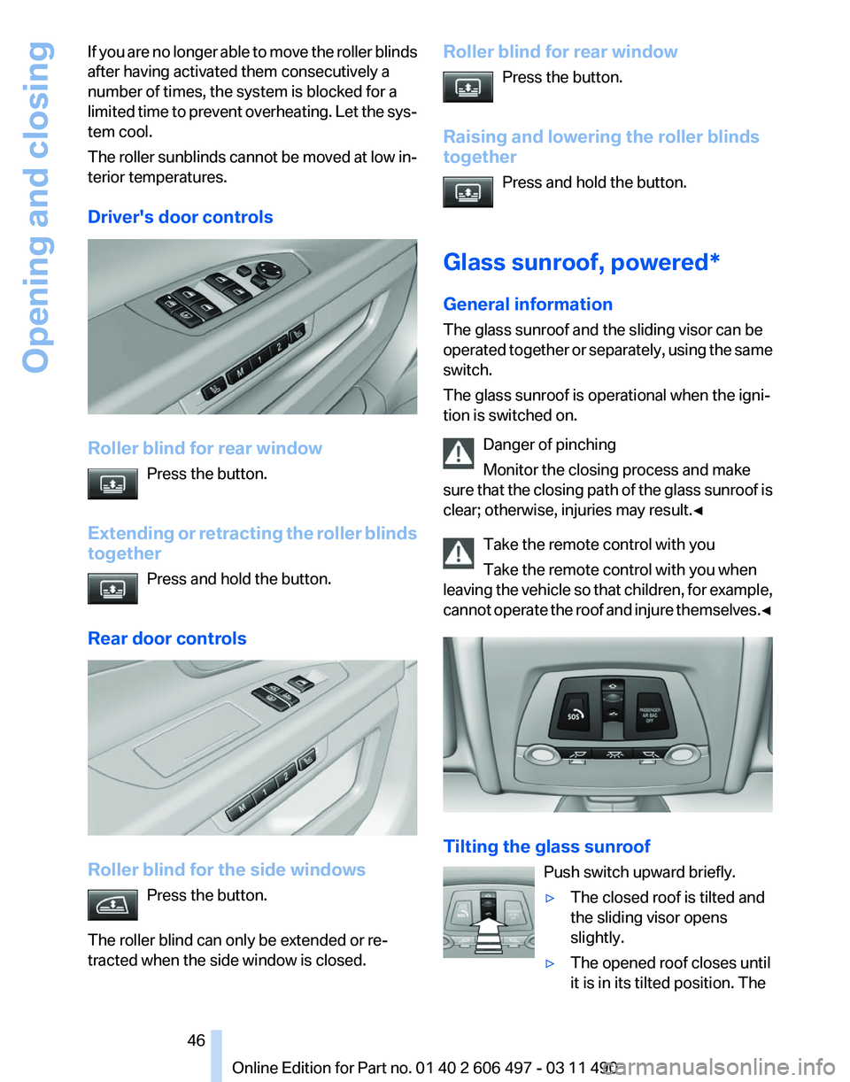
Driver's door controls Roller blind for rear window
Press the button.
Extending
or retracting the roller blinds
together
Press and hold the button.
Rear door controls Roller blind for the side windows
Press the button.
The roller blind can only be extended or re‐
tracted when the side window is closed. Roller blind for rear window
Press the button.
Raising and lowering the roller blinds
together Press and hold the button.
Glass sunroof, powered*
General information
The glass sunroof and the sliding visor can be
operated
together or separately, using the same
switch.
The glass sunroof is operational when the igni‐
tion is switched on.
Danger of pinching
Monitor the closing process and make
sure that the closing path of the glass sunroof is
clear; otherwise, injuries may result.◀
Take the remote control with you
Take the remote control with you when
leaving the vehicle so that children, for example,
cannot operate the roof and injure themselves.◀ Tilting the glass sunroof
Push switch upward briefly.
▷The closed roof is tilted and
the sliding visor opens
slightly.
▷ The opened roof closes until
it is in its tilted position. The Seite 46
46 Online Edition for Part no. 01 40 2 606 497 - 03 11 490
Opening and closing
Page 47 of 299
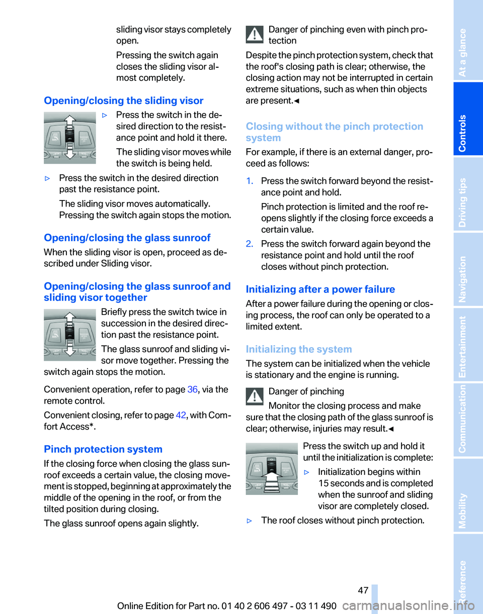
sliding visor stays completely
open.
Pressing the switch again
closes the sliding visor al‐
most completely.
Opening/closing the sliding visor ▷Press the switch in the de‐
sired direction to the resist‐
ance point and hold it there.
The
sliding visor moves while
the switch is being held.
▷ Press the switch in the desired direction
past the resistance point.
The sliding visor moves automatically.
Pressing
the switch again stops the motion.
Opening/closing the glass sunroof
When the sliding visor is open, proceed as de‐
scribed under Sliding visor.
Opening/closing the glass sunroof and
sliding visor together Briefly press the switch twice in
succession in the desired direc‐
tion past the resistance point.
The glass sunroof and sliding vi‐
sor move together. Pressing the
switch again stops the motion.
Convenient operation, refer to page 36, via the
remote control.
Convenient
closing, refer to page 42, with Com‐
fort Access*.
Pinch protection system
If the closing force when closing the glass sun‐
roof exceeds a certain value, the closing move‐
ment is stopped, beginning at approximately the
middle of the opening in the roof, or from the
tilted position during closing.
The glass sunroof opens again slightly. Danger of pinching even with pinch pro‐
tection
Despite
the pinch protection system, check that
the roof's closing path is clear; otherwise, the
closing action may not be interrupted in certain
extreme situations, such as when thin objects
are present.◀
Closing without the pinch protection
system
For example, if there is an external danger, pro‐
ceed as follows:
1. Press the switch forward beyond the resist‐
ance point and hold.
Pinch protection is limited and the roof re‐
opens
slightly if the closing force exceeds a
certain value.
2. Press the switch forward again beyond the
resistance point and hold until the roof
closes without pinch protection.
Initializing after a power failure
After
a power failure during the opening or clos‐
ing process, the roof can only be operated to a
limited extent.
Initializing the system
The system can be initialized when the vehicle
is stationary and the engine is running.
Danger of pinching
Monitor the closing process and make
sure that the closing path of the glass sunroof is
clear; otherwise, injuries may result.◀
Press the switch up and hold it
until the initialization is complete:
▷Initialization begins within
15
seconds and is completed
when the sunroof and sliding
visor are completely closed.
▷ The roof closes without pinch protection. Seite 47
47Online Edition for Part no. 01 40 2 606 497 - 03 11 490
Reference Mobility Communication Entertainment Navigation Driving tips
Controls At a glance
Page 50 of 299
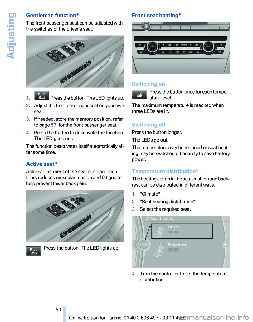
Gentleman function*
The front passenger seat can be adjusted with
the switches of the driver's seat.
1. Press the button. The LED lights up.
2. Adjust the front passenger seat on your own
seat.
3. If needed, store the memory position, refer
to page 57, for the front passenger seat.
4. Press the button to deactivate the function.
The LED goes out.
The function deactivates itself automatically af‐
ter some time.
Active seat*
Active adjustment of the seat cushion's con‐
tours reduces muscular tension and fatigue to
help prevent lower back pain. Press the button. The LED lights up. Front seat heating*
Switching on
Press the button once for each temper‐
ature level.
The maximum temperature is reached when
three LEDs are lit.
Switching off
Press the button longer.
The LEDs go out.
The temperature may be reduced or seat heat‐
ing may be switched off entirely to save battery
power.
Temperature distribution*
The heating action in the seat cushion and back‐
rest can be distributed in different ways.
1. "Climate"
2. "Seat heating distribution"
3. Select the required seat. 4.
Turn the controller to set the temperature
distribution. Seite 50
50 Online Edition for Part no. 01 40 2 606 497 - 03 11 490
Adjusting
Page 54 of 299
One person per safety belt
Never
allow more than one person to wear
a single safety belt. Never allow infants or small
children to ride on a passenger's lap.◀
Putting on the belt
Lay the belt, without twisting, snugly
across the lap and shoulders, as close to the
body as possible. Make sure that the belt lies low
around the hips in the lap area and does not
press on the abdomen. Otherwise, the belt can
slip over the hips in the lap area in a frontal im‐
pact and injure the abdomen.
The safety belt must not lie across the neck, rub
on sharp edges, be routed over solid or breaka‐
ble objects, or be pinched.◀
Reduction of restraining effect
Avoid wearing clothing that prevents the
belt from fitting properly, and pull the shoulder
belt periodically to readjust the tension across
your lap; otherwise, the retention effect of the
safety belt may be reduced.◀
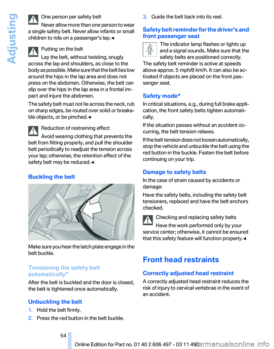
Buckling the belt Make sure you hear the latch plate engage in the
belt buckle.
Tensioning the safety belt
automatically*
After the belt is buckled and the door is closed,
the belt is tightened once automatically.
Unbuckling the belt
1.
Hold the belt firmly.
2. Press the red button in the belt buckle. 3.
Guide the belt back into its reel.
Safety belt reminder for the driver's and
front passenger seat The indicator lamp flashes or lights up
and a signal sounds. Make sure that the
safety belts are positioned correctly.
The safety belt reminder is active at speeds
above approx. 5 mph/8 km/h. It can also be ac‐
tivated if objects are placed on the front pas‐
senger seat.
Safety mode*
In
critical situations, e.g., during full brake appli‐
cation, the front safety belts tighten automati‐
cally.
If the situation passes without an accident oc‐
curring, the belt tension relaxes.
If the belt tension does not loosen automatically,
stop the vehicle and unbuckle the belt using the
red button in the buckle. Fasten the belt before
continuing on your trip.
Damage to safety belts
In the case of strain caused by accidents or
damage:
Have the safety belts, including the safety belt
tensioners, replaced and have the belt anchors
checked.
Checking and replacing safety belts
Have the work performed only by your
service center; otherwise, it cannot be ensured
that this safety feature will function properly.◀
Front head restraints
Correctly adjusted head restraint
A correctly adjusted head restraint reduces the
risk of injury to cervical vertebrae in the event of
an accident. Seite 54
54 Online Edition for Part no. 01 40 2 606 497 - 03 11 490
Adjusting
Page 57 of 299
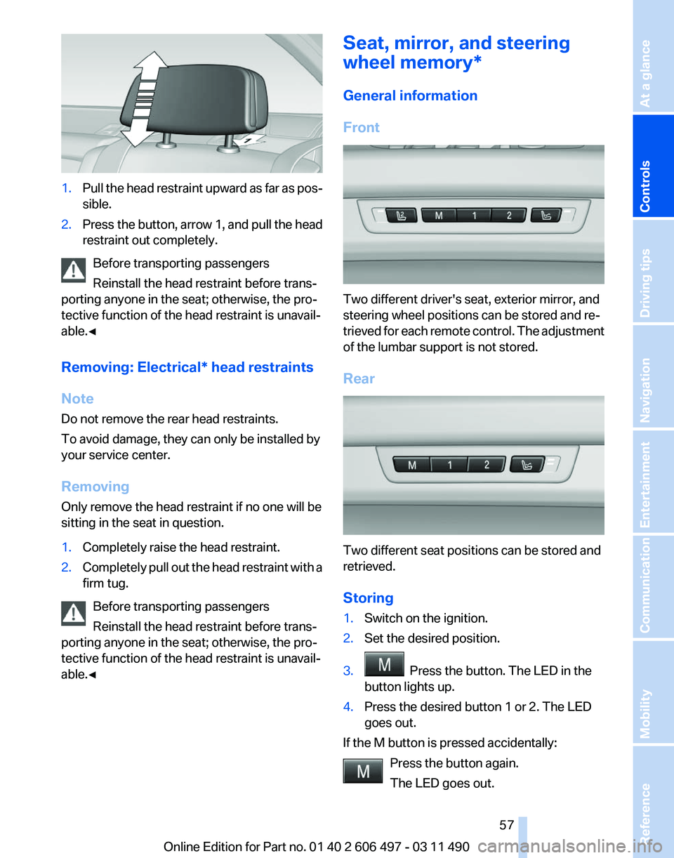
1.
Pull the head restraint upward as far as pos‐
sible.
2. Press the button, arrow 1, and pull the head
restraint out completely.
Before transporting passengers
Reinstall the head restraint before trans‐
porting anyone in the seat; otherwise, the pro‐
tective function of the head restraint is unavail‐
able.◀
Removing: Electrical
* head restraints
Note
Do not remove the rear head restraints.
To avoid damage, they can only be installed by
your service center.
Removing
Only remove the head restraint if no one will be
sitting in the seat in question.
1. Completely raise the head restraint.
2. Completely pull out the head restraint with a
firm tug.
Before transporting passengers
Reinstall the head restraint before trans‐
porting anyone in the seat; otherwise, the pro‐
tective function of the head restraint is unavail‐
able.◀ Seat, mirror, and steering
wheel memory*
General information
Front
Two different driver's seat, exterior mirror, and
steering wheel positions can be stored and re‐
trieved
for each remote control. The adjustment
of the lumbar support is not stored.
Rear Two different seat positions can be stored and
retrieved.
Storing
1.
Switch on the ignition.
2. Set the desired position.
3. Press the button. The LED in the
button lights up.
4. Press the desired button 1 or 2. The LED
goes out.
If the M button is pressed accidentally: Press the button again.
The LED goes out. Seite 57
57Online Edition for Part no. 01 40 2 606 497 - 03 11 490
Reference Mobility Communication Entertainment Navigation Driving tips
Controls At a glance
Page 59 of 299
Storing positions*
Seat, mirror, and steering wheel memory, refer
to page
57.
Adjusting manually
If an electrical malfunction occurs, for example,
press the edges of the mirror glass.
Automatic Curb Monitor*
When the reverse gear is engaged, the mirror
glass tilts downward slightly on the front pas‐
senger
side. This improves your view of the curb
and other low-lying obstacles when parking, for
example.
Activating
1. Slide the mirror changeover switch
to the driver's side mirror position.
2. Engage transmission position R.
Deactivating
Slide the mirror changeover switch to the pas‐
senger's side mirror position.
Fold in and out* Press the button.
Possible up to approx. 15 mph/20 km/h.
For example, this is advantageous
▷ In car washes.
▷ In narrow streets.
▷ For folding back mirrors that were folded
away manually.
Mirrors that were folded in are folded out auto‐
matically
at a speed of approx. 25 mph/40 km/h.
Fold in the mirror in a car wash
Before entering an automatic car wash,
fold in the exterior mirrors by hand or with the
button; otherwise, they could be damaged, de‐
pending on the width of the vehicle.◀ Automatic heating
Both exterior mirrors are automatically heated
whenever the engine is running.
Automatic dimming feature
Both
exterior mirrors are automatically dimmed.
Photocells are used for control in the Interior rear
view mirror, refer to page 59.
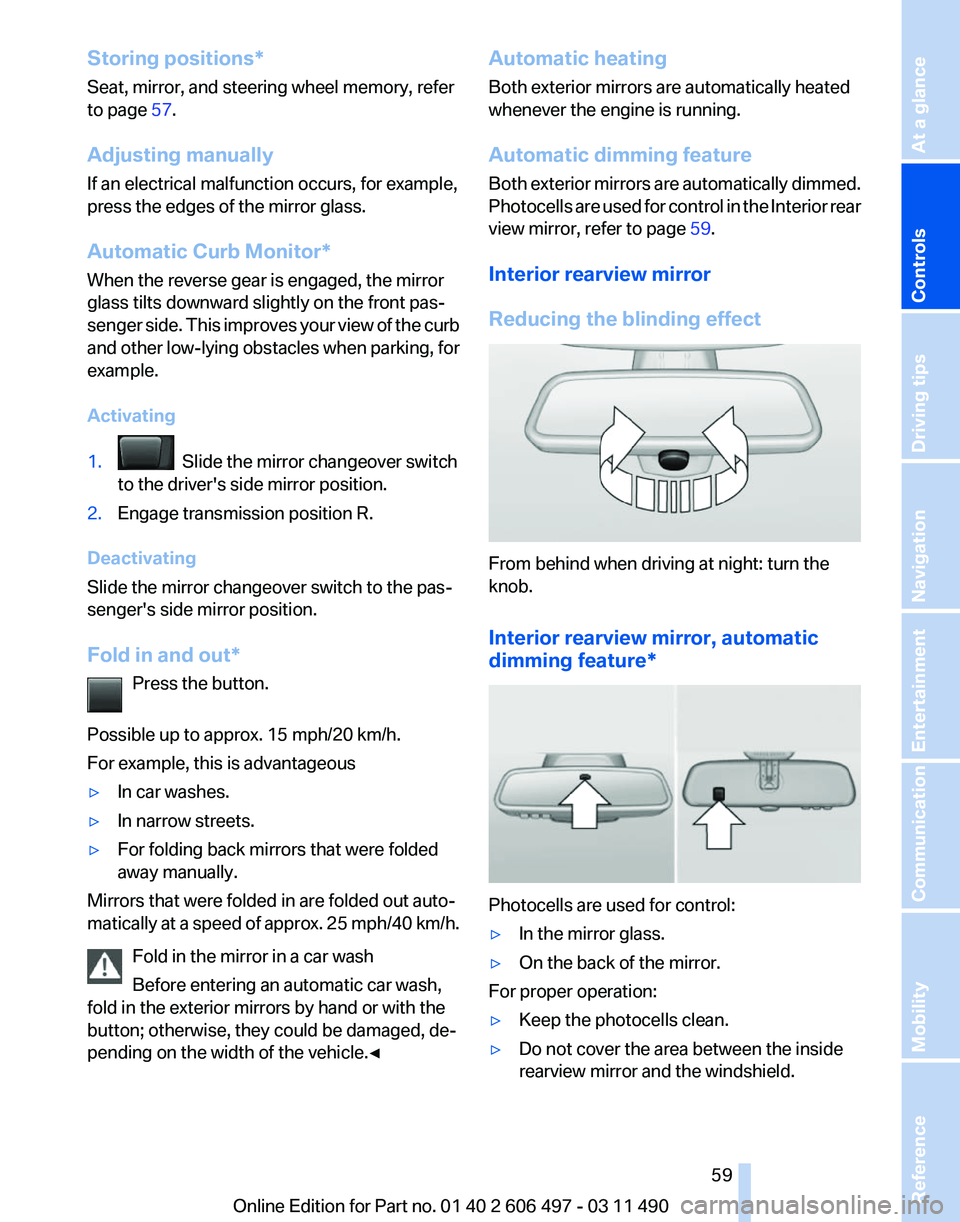
Interior rearview mirror
Reducing the blinding effect From behind when driving at night: turn the
knob.
Interior rearview mirror, automatic
dimming feature
* Photocells are used for control:
▷
In the mirror glass.
▷ On the back of the mirror.
For proper operation:
▷ Keep the photocells clean.
▷ Do not cover the area between the inside
rearview mirror and the windshield.
Seite 59
59Online Edition for Part no. 01 40 2 606 497 - 03 11 490
Reference Mobility Communication Entertainment Navigation Driving tips
Controls At a glance
Page 60 of 299
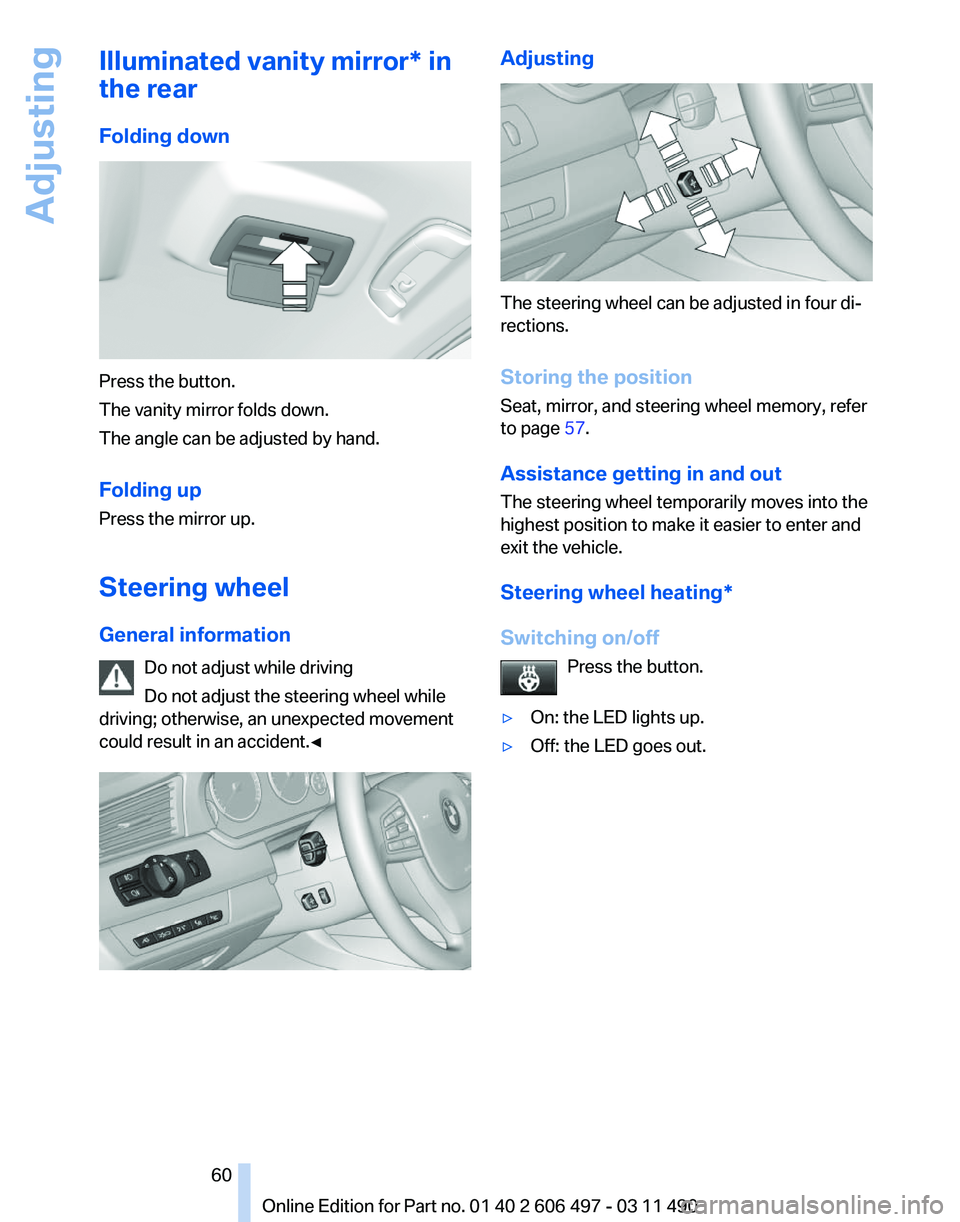
Illuminated vanity mirror* in
the rear
Folding down
Press the button.
The vanity mirror folds down.
The angle can be adjusted by hand.
Folding up
Press the mirror up.
Steering wheel
General information
Do not adjust while driving
Do not adjust the steering wheel while
driving; otherwise, an unexpected movement
could result in an accident.◀ Adjusting
The steering wheel can be adjusted in four di‐
rections.
Storing the position
Seat, mirror, and steering wheel memory, refer
to page
57.
Assistance getting in and out
The steering wheel temporarily moves into the
highest position to make it easier to enter and
exit the vehicle.
Steering wheel heating
*
Switching on/off Press the button.
▷ On: the LED lights up.
▷ Off: the LED goes out. Seite 60
60 Online Edition for Part no. 01 40 2 606 497 - 03 11 490
Adjusting
Page 63 of 299
Mounting LATCH child restraint fixing
systems on power rear seats
*
1. Before mounting, adjust the seats to their
basic position, refer to page 52.
2. For better accessibility, tilt the backrest
back slightly.
3. Mount the child restraint fixing system; refer
to the operating instructions of the system.
4. Ensure that both LATCH anchors are prop‐
erly connected.
5. After mounting, move the backrest back up
slightly so that the child restraint fixing sys‐
tem rests lightly against the backrest.
Child restraint fixing system with a
tether strap LATCH mounting eyes
Only
use the mounting eyes for the upper
LATCH retaining strap to secure child restraint
fixing systems; otherwise, the mounting eyes
could be damaged.◀
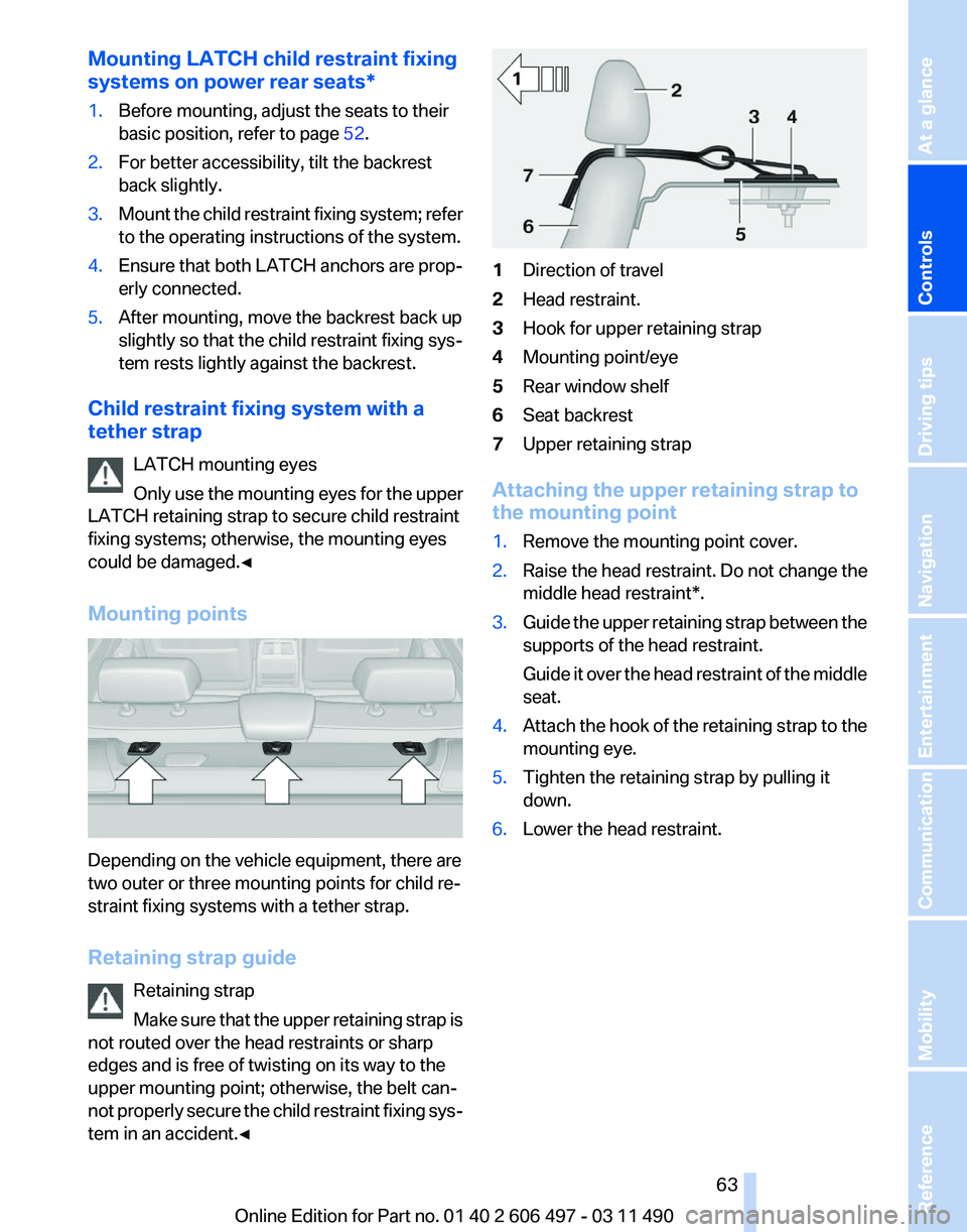
Mounting points Depending on the vehicle equipment, there are
two outer or three mounting points for child re‐
straint fixing systems with a tether strap.
Retaining strap guide
Retaining strap
Make
sure that the upper retaining strap is
not routed over the head restraints or sharp
edges and is free of twisting on its way to the
upper mounting point; otherwise, the belt can‐
not properly secure the child restraint fixing sys‐
tem in an accident.◀ 1
Direction of travel
2 Head restraint.
3 Hook for upper retaining strap
4 Mounting point/eye
5 Rear window shelf
6 Seat backrest
7 Upper retaining strap
Attaching the upper retaining strap to
the mounting point
1. Remove the mounting point cover.
2. Raise the head restraint. Do not change the
middle head restraint*.
3. Guide the upper retaining strap between the
supports of the head restraint.
Guide
it over the head restraint of the middle
seat.
4. Attach the hook of the retaining strap to the
mounting eye.
5. Tighten the retaining strap by pulling it
down.
6. Lower the head restraint.
Seite 63
63Online Edition for Part no. 01 40 2 606 497 - 03 11 490
Reference Mobility Communication Entertainment Navigation Driving tips
Controls At a glance