BMW 760Li 2004 E66 Owner's Manual
Manufacturer: BMW, Model Year: 2004, Model line: 760Li, Model: BMW 760Li 2004 E66Pages: 232, PDF Size: 5.27 MB
Page 201 of 232
Mobility
199Reference
At a glance
Controls
Driving tips
Communications
Navigation
Entertainment
Rules and regulations
California Proposition 65
Warning
California laws require us to issue the fol-
lowing warning:
Engine exhaust and a wide variety of
automobile components and parts,
including components found in the interior
furnishings in a vehicle, contain or emit
chemicals known to the State of California
to cause cancer and birth defects and
reproductive harm. In addition, certain flu-
ids contained in vehicles and certain prod-
ucts of component wear contain or emit
chemicals known to the State of California
to cause cancer and birth defects or other
reproductive harm.
Battery posts, terminals and related acces-
sories contain lead and lead compounds.
Wash your hands after handling.
Used engine oil contains chemicals that
have caused cancer in laboratory animals.
Always protect your skin by washing thor-
oughly with soap and water.<
OBD connector
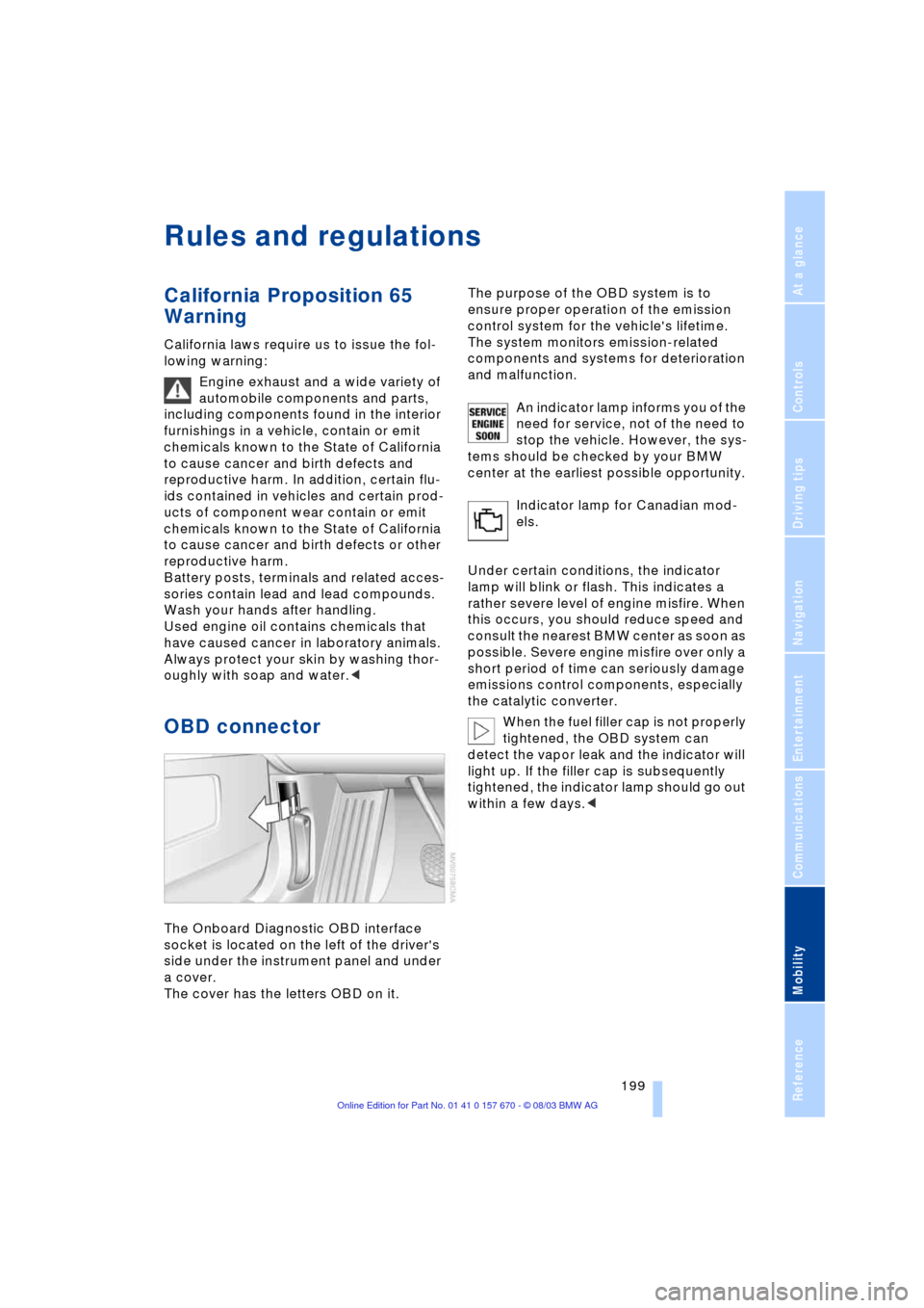
The Onboard Diagnostic OBD interface
socket is located on the left of the driver's
side under the instrument panel and under
a cover.
The cover has the letters OBD on it.The purpose of the OBD system is to
ensure proper operation of the emission
control system for the vehicle's lifetime.
The system monitors emission-related
components and systems for deterioration
and malfunction.
An indicator lamp informs you of the
need for service, not of the need to
stop the vehicle. However, the sys-
tems should be checked by your BMW
center at the earliest possible opportunity.
Indicator lamp for Canadian mod-
els.
Under certain conditions, the indicator
lamp will blink or flash. This indicates a
rather severe level of engine misfire. When
this occurs, you should reduce speed and
consult the nearest BMW center as soon as
possible. Severe engine misfire over only a
short period of time can seriously damage
emissions control components, especially
the catalytic converter.
When the fuel filler cap is not properly
tightened, the OBD system can
detect the vapor leak and the indicator will
light up. If the filler cap is subsequently
tightened, the indicator lamp should go out
within a few days.<
Page 202 of 232
Replacing components
200
Replacing components
Onboard tool kit
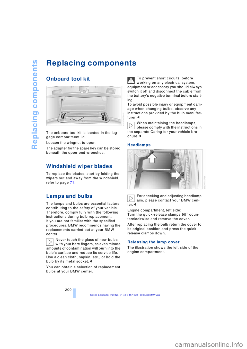
The onboard tool kit is located in the lug-
gage compartment lid.
Loosen the wingnut to open.
The adapter for the spare key can be stored
beneath the open-end wrenches.
Windshield wiper blades
To replace the blades, start by folding the
wipers out and away from the windshield,
refer to page 71.
Lamps and bulbs
The lamps and bulbs are essential factors
contributing to the safety of your vehicle.
Therefore, comply fully with the following
instructions during bulb replacement.
If you are not familiar with the specified
procedures, BMW recommends having the
replacements carried out at your BMW
center.
Never touch the glass of new bulbs
with your bare fingers, as even minute
amounts of contamination will burn into the
bulb's surface and reduce its service life.
Use a clean cloth, napkin, etc., or hold the
bulb by its metal socket.<
You can obtain a selection of replacement
bulbs at your BMW center. To prevent short circuits, before
working on any electrical system,
equipment or accessory you should always
switch it off and disconnect the cable from
the battery's negative terminal before start-
ing.
To avoid possible injury or equipment dam-
age when changing bulbs, observe any
instructions provided by the bulb manufac-
turer.<
When maintaining the headlamps,
please comply with the instructions in
the separate Caring for your vehicle bro-
chure.<
Headlamps
For checking and adjusting headlamp
aim, please contact your BMW cen-
ter.<
Engine compartment, left side:
Turn the quick-release clamps 905 coun-
terclockwise and remove the cover.
After replacing the bulb return the cover to
its original position and press the quick-
release clamps down.
Releasing the lamp cover
The illustration shows the left side of the
engine compartment.
Page 203 of 232
Mobility
201Reference
At a glance
Controls
Driving tips
Communications
Navigation
Entertainment
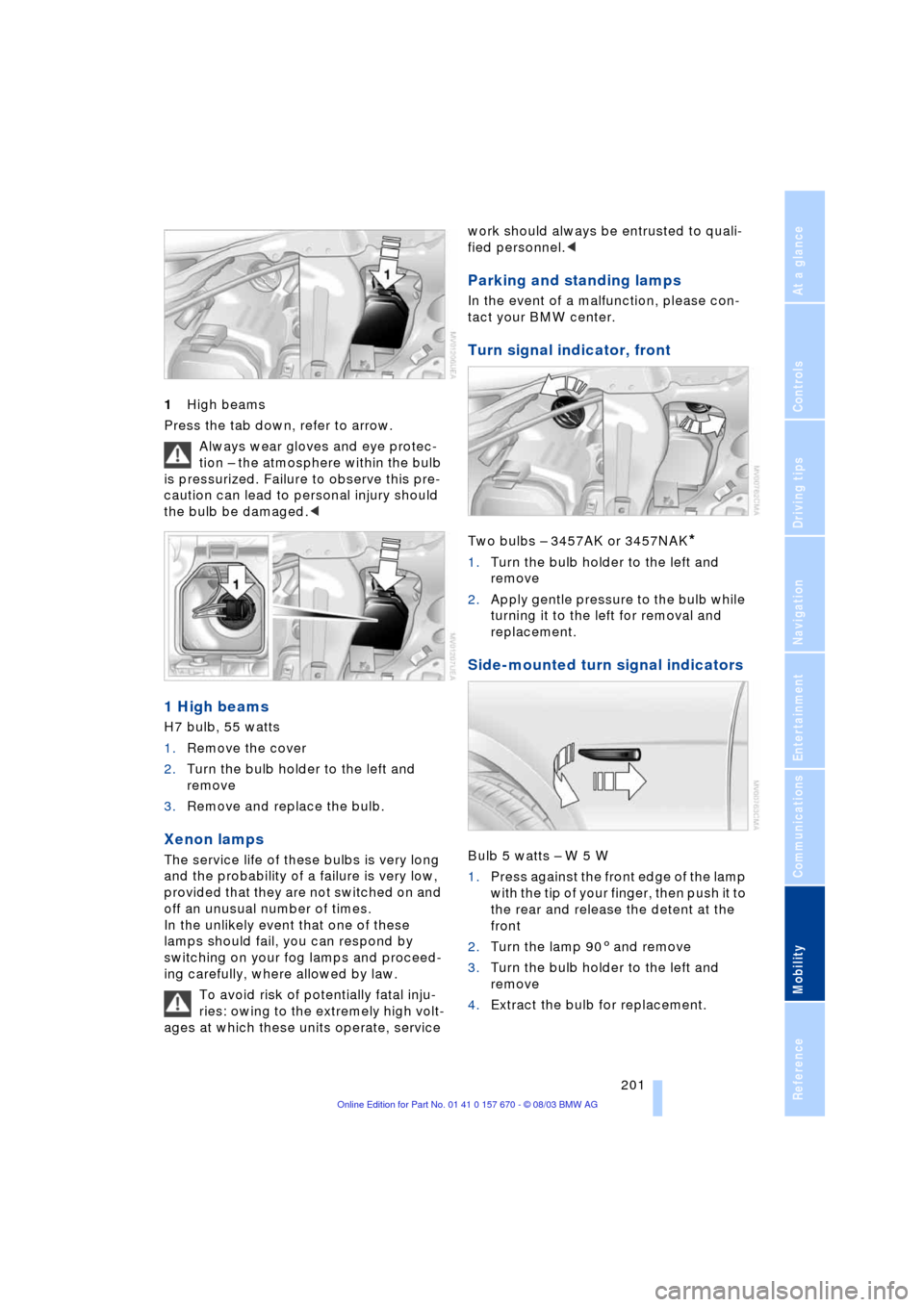
1High beams
Press the tab down, refer to arrow.
Always wear gloves and eye protec-
tion Ð the atmosphere within the bulb
is pressurized. Failure to observe this pre-
caution can lead to personal injury should
the bulb be damaged.<
1 High beams
H7 bulb, 55 watts
1.Remove the cover
2.Turn the bulb holder to the left and
remove
3.Remove and replace the bulb.
Xenon lamps
The service life of these bulbs is very long
and the probability of a failure is very low,
provided that they are not switched on and
off an unusual number of times.
In the unlikely event that one of these
lamps should fail, you can respond by
switching on your fog lamps and proceed-
ing carefully, where allowed by law.
To avoid risk of potentially fatal inju-
ries: owing to the extremely high volt-
ages at which these units operate, service work should always be entrusted to quali-
fied personnel.<
Parking and standing lamps
In the event of a malfunction, please con-
tact your BMW center.
Turn signal indicator, front
Two bulbs Ð 3457AK or 3457NAK*
1.Turn the bulb holder to the left and
remove
2.Apply gentle pressure to the bulb while
turning it to the left for removal and
replacement.
Side-mounted turn signal indicators
Bulb 5 watts Ð W 5 W
1.Press against the front edge of the lamp
with the tip of your finger, then push it to
the rear and release the detent at the
front
2.Turn the lamp 903 and remove
3.Turn the bulb holder to the left and
remove
4.Extract the bulb for replacement.
Page 204 of 232
Replacing components
202
Side marker lamps, front and rear
Please contact your BMW center for
replacement.
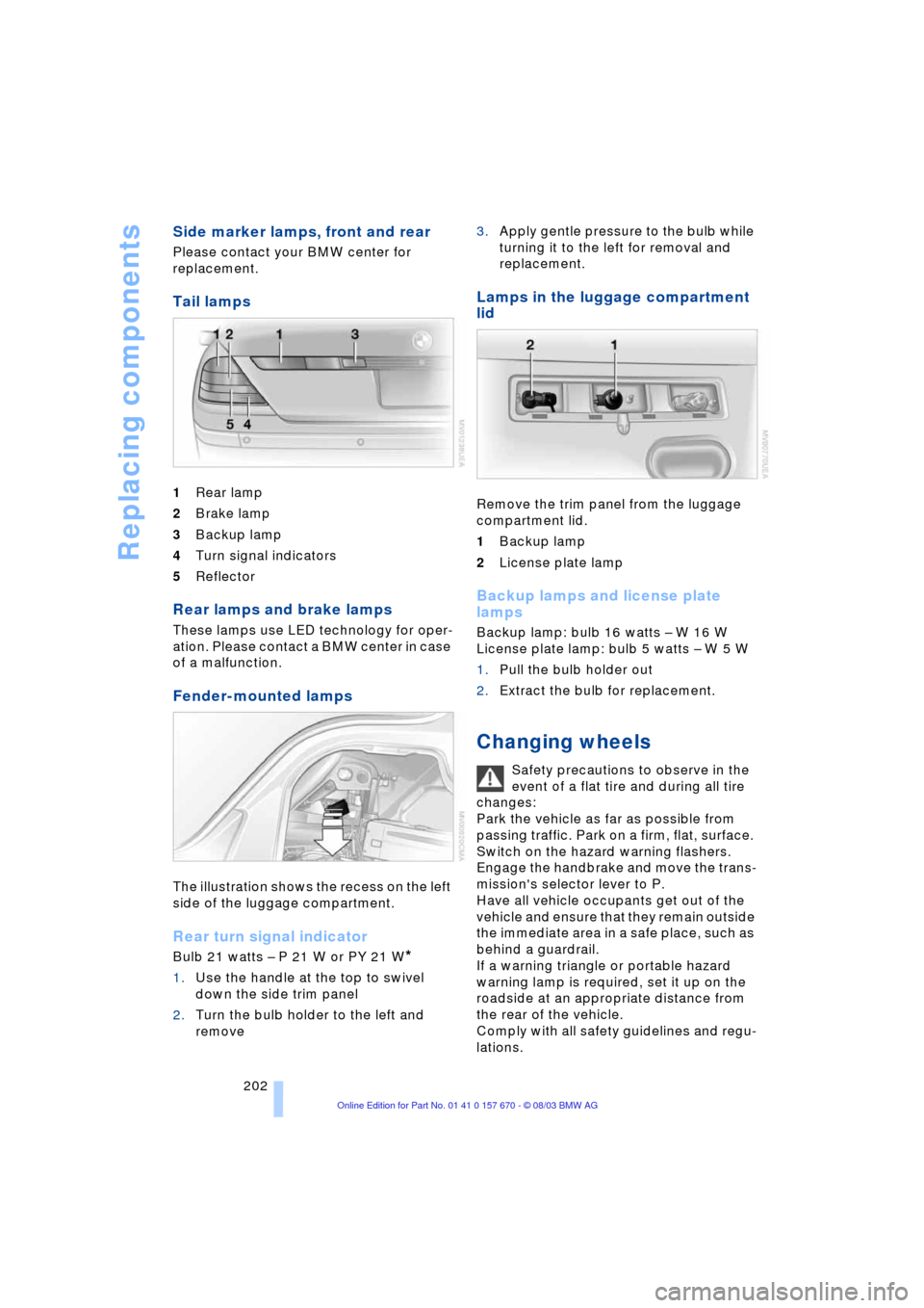
Tail lamps
1Rear lamp
2Brake lamp
3Backup lamp
4Turn signal indicators
5Reflector
Rear lamps and brake lamps
These lamps use LED technology for oper-
ation. Please contact a BMW center in case
of a malfunction.
Fender-mounted lamps
The illustration shows the recess on the left
side of the luggage compartment.
Rear turn signal indicator
Bulb 21 watts Ð P 21 W or PY 21 W*
1.Use the handle at the top to swivel
down the side trim panel
2.Turn the bulb holder to the left and
remove 3.Apply gentle pressure to the bulb while
turning it to the left for removal and
replacement.
Lamps in the luggage compartment
lid
Remove the trim panel from the luggage
compartment lid.
1Backup lamp
2License plate lamp
Backup lamps and license plate
lamps
Backup lamp: bulb 16 watts Ð W 16 W
License plate lamp: bulb 5 watts Ð W 5 W
1.Pull the bulb holder out
2.Extract the bulb for replacement.
Changing wheels
Safety precautions to observe in the
event of a flat tire and during all tire
changes:
Park the vehicle as far as possible from
passing traffic. Park on a firm, flat, surface.
Switch on the hazard warning flashers.
Engage the handbrake and move the trans-
mission's selector lever to P.
Have all vehicle occupants get out of the
vehicle and ensure that they remain outside
the immediate area in a safe place, such as
behind a guardrail.
If a warning triangle or portable hazard
warning lamp is required, set it up on the
roadside at an appropriate distance from
the rear of the vehicle.
Comply with all safety guidelines and regu-
lations.
Page 205 of 232
Mobility
203Reference
At a glance
Controls
Driving tips
Communications
Navigation
Entertainment
Change the wheel only on a level, firm sur-
face which is not slippery. The vehicle or
the jack could slip to the side if you attempt
to raise the vehicle on a soft or slippery sur-
face such as snow, ice, tiles, etc.
Position the jack on a firm support surface.
Do not use a wooden block or similar
object as a support base for the jack, as
this would prevent it from extending to its
full support height and reduce its load-car-
rying capacity.
To avoid serious or fatal injury: never lie
under the vehicle, and never start the
engine while it is supported by the jack.<
What you will need
To avoid rattling noises, note the positions
of the tools before removing them, then
return them to their initial positions after
completing work.
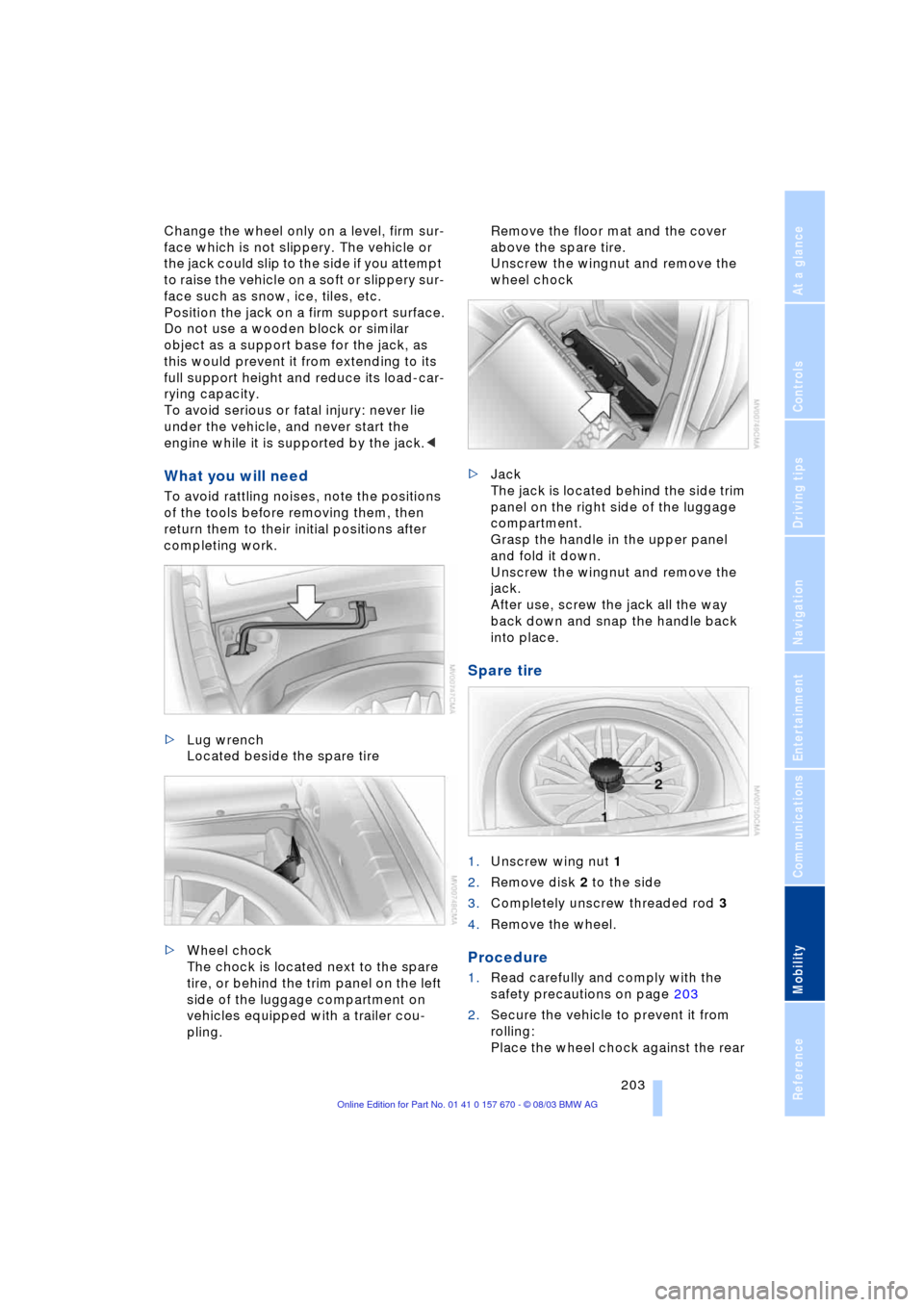
>Lug wrench
Located beside the spare tire
>Wheel chock
The chock is located next to the spare
tire, or behind the trim panel on the left
side of the luggage compartment on
vehicles equipped with a trailer cou-
pling. Remove the floor mat and the cover
above the spare tire.
Unscrew the wingnut and remove the
wheel chock
>Jack
The jack is located behind the side trim
panel on the right side of the luggage
compartment.
Grasp the handle in the upper panel
and fold it down.
Unscrew the wingnut and remove the
jack.
After use, screw the jack all the way
back down and snap the handle back
into place.
Spare tire
1.Unscrew wing nut 1
2.Remove disk 2 to the side
3.Completely unscrew threaded rod 3
4.Remove the wheel.
Procedure
1.Read carefully and comply with the
safety precautions on page 203
2.Secure the vehicle to prevent it from
rolling:
Place the wheel chock against the rear
Page 206 of 232
Replacing components
204 surface of the front tire on the side
opposite the side being raised. If the
vehicle is parked on a downward slope,
place the wheel chock securely in front
of the tire. If the wheel must be changed
on a surface with a more severe slope,
take additional precautions to secure
the vehicle from rolling
3.Loosen the lug bolts 1/2 a turn
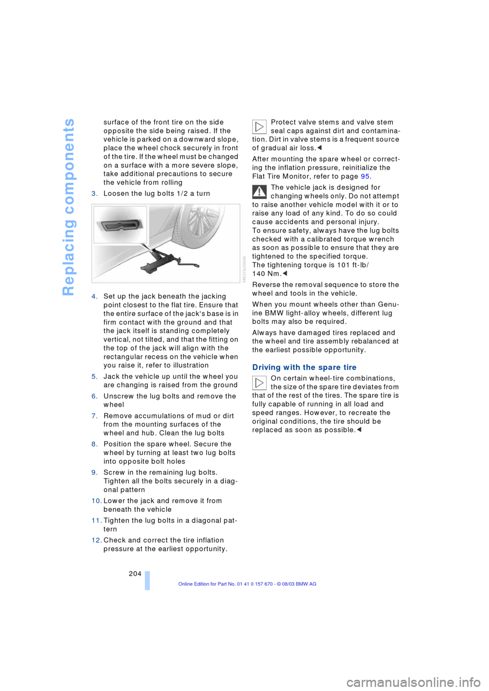
4.Set up the jack beneath the jacking
point closest to the flat tire. Ensure that
the entire surface of the jack's base is in
firm contact with the ground and that
the jack itself is standing completely
vertical, not tilted, and that the fitting on
the top of the jack will align with the
rectangular recess on the vehicle when
you raise it, refer to illustration
5.Jack the vehicle up until the wheel you
are changing is raised from the ground
6.Unscrew the lug bolts and remove the
wheel
7.Remove accumulations of mud or dirt
from the mounting surfaces of the
wheel and hub. Clean the lug bolts
8.Position the spare wheel. Secure the
wheel by turning at least two lug bolts
into opposite bolt holes
9.Screw in the remaining lug bolts.
Tighten all the bolts securely in a diag-
onal pattern
10.Lower the jack and remove it from
beneath the vehicle
11.Tighten the lug bolts in a diagonal pat-
tern
12.Check and correct the tire inflation
pressure at the earliest opportunity. Protect valve stems and valve stem
seal caps against dirt and contamina-
tion. Dirt in valve stems is a frequent source
of gradual air loss.<
After mounting the spare wheel or correct-
ing the inflation pressure, reinitialize the
Flat Tire Monitor, refer to page 95.
The vehicle jack is designed for
changing wheels only. Do not attempt
to raise another vehicle model with it or to
raise any load of any kind. To do so could
cause accidents and personal injury.
To ensure safety, always have the lug bolts
checked with a calibrated torque wrench
as soon as possible to ensure that they are
tightened to the specified torque.
The tightening torque is 101 ft-lb/
140 Nm.<
Reverse the removal sequence to store the
wheel and tools in the vehicle.
When you mount wheels other than Genu-
ine BMW light-alloy wheels, different lug
bolts may also be required.
Always have damaged tires replaced and
the wheel and tire assembly rebalanced at
the earliest possible opportunity.
Driving with the spare tire
On certain wheel-tire combinations,
the size of the spare tire deviates from
that of the rest of the tires. The spare tire is
fully capable of running in all load and
speed ranges. However, to recreate the
original conditions, the tire should be
replaced as soon as possible.<
Page 207 of 232
Mobility
205Reference
At a glance
Controls
Driving tips
Communications
Navigation
Entertainment
Run-flat tires*
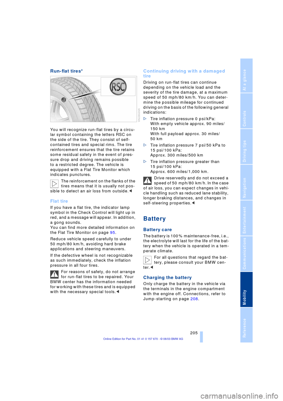
You will recognize run-flat tires by a circu-
lar symbol containing the letters RSC on
the side of the tire. They consist of self-
contained tires and special rims. The tire
reinforcement ensures that the tire retains
some residual safety in the event of pres-
sure drop and driving remains possible
to a restricted degree. The vehicle is
equipped with a Flat Tire Monitor which
indicates punctures.
The reinforcement on the flanks of the
tires means that it is usually not pos-
sible to detect an air loss from outside.<
Flat tire
If you have a flat tire, the indicator lamp
symbol in the Check Control will light up in
red, and a message will appear. In addition,
a gong sounds.
You can find more detailed information on
the Flat Tire Monitor on page 95.
Reduce vehicle speed carefully to under
50 mph/80 km/h, avoiding hard brake
applications and steering maneuvers.
If the defective wheel is not recognizable
as such immediately, check the inflation
pressure in all four tires.
For reasons of safety, do not arrange
for run-flat tires to be repaired. Your
BMW center has the information needed
for working with these tires and is equipped
with the necessary special tools.<
Continuing driving with a damaged
tire
Driving on run-flat tires can continue
depending on the vehicle load and the
severity of the tire damage, at a maximum
speed of 50 mph/80 km/h. You can deter-
mine the possible mileage for continued
driving on the basis of the following general
indications:
>Tire inflation pressure 0 psi/kPa:
With empty vehicle approx. 90 miles/
150 km
With full payload approx. 30 miles/
50 km
>Tire inflation pressure 7 psi/50 kPa to
15 psi/100 kPa:
Approx. 300 miles/500 km
>Tire inflation pressure greater than
15 psi/100 kPa:
Approx. 600 miles/1,000 km.
Drive reservedly and do not exceed a
speed of 50 mph/80 km/h. In the case
of air loss, you can expect changes in vehi-
cle handling such as reduced lane stability,
longer braking distances, and changes in
self-steering properties.<
Battery
Battery care
The battery is 100 % maintenance-free, i.e.,
the electrolyte will last for the life of the bat-
tery when the vehicle is operated in a tem-
perate climate.
For all questions that regard the bat-
tery, please consult your BMW cen-
ter.<
Charging the battery
Only charge the battery in the vehicle via
the terminals in the engine compartment
with the engine off. Connections, refer to
Jump-starting on page 208.
Page 208 of 232
Replacing components
206
Battery switch
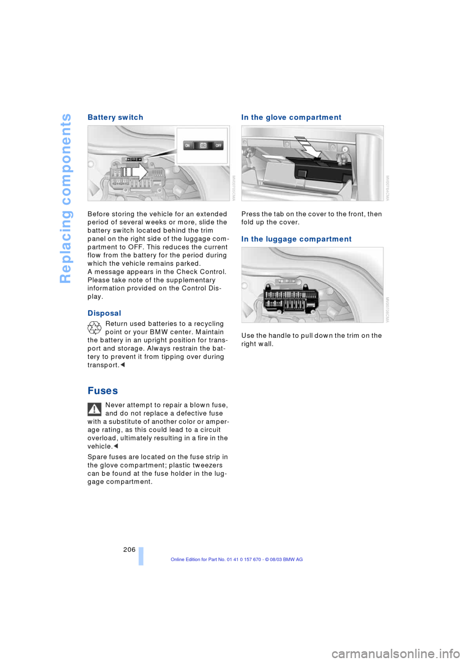
Before storing the vehicle for an extended
period of several weeks or more, slide the
battery switch located behind the trim
panel on the right side of the luggage com-
partment to OFF. This reduces the current
flow from the battery for the period during
which the vehicle remains parked.
A message appears in the Check Control.
Please take note of the supplementary
information provided on the Control Dis-
play.
Disposal
Return used batteries to a recycling
point or your BMW center. Maintain
the battery in an upright position for trans-
port and storage. Always restrain the bat-
tery to prevent it from tipping over during
transport.<
Fuses
Never attempt to repair a blown fuse,
and do not replace a defective fuse
with a substitute of another color or amper-
age rating, as this could lead to a circuit
overload, ultimately resulting in a fire in the
vehicle.<
Spare fuses are located on the fuse strip in
the glove compartment; plastic tweezers
can be found at the fuse holder in the lug-
gage compartment.
In the glove compartment
Press the tab on the cover to the front, then
fold up the cover.
In the luggage compartment
Use the handle to pull down the trim on the
right wall.
Page 209 of 232
Mobility
207Reference
At a glance
Controls
Driving tips
Communications
Navigation
Entertainment
Giving and receiving assistance
Warning triangle*
The warning triangle is conveniently stored
in the onboard tool kit mounted on the
inside of the luggage compartment lid.
Comply with legal requirements
requiring you to carry a hazard warn-
ing triangle in the vehicle.<
First-aid kit*
You will also find the first-aid kit in the
onboard tool kit's container.
Some of the articles contained in the
first-aid kit have a limited service life.
For this reason, check the expiration dates
of each of the items regularly, and replace
any whose expiration dates have passed.
You can find replacements in any phar-
macy.
Always comply with laws requiring a first-
aid kit to be carried in the vehicle.<
Jump-starting
When your battery is discharged you can
use two jumper cables to start your vehicle
with power from the battery in a second
vehicle. You can also use the same method
to help start another vehicle. Use only
jumper cables with fully-insulated clamp
handles.To avoid the risk of potentially fatal
injury, always avoid all contact with
electrical components while the engine is
running. Carefully adhere to the following
sequence, both to prevent damage to one
or both vehicles, and to guard against pos-
sible personal injury.<
Preparing
1.Check whether the battery of the other
vehicle has a voltage of 12 Volts and
approximately the same capacitance
in Ah. This information can be found on
the battery
2.Switch off the engine of the support
vehicle
3.Switch off any electrical systems and
components in both vehicles.
Ensure that no contact exists
between the bodywork on the two
vehicles, otherwise there is a danger of
short circuits.<
Connecting the jumper cables
To avoid personal injury from sparks,
always observe this sequence when
connecting jumper cables.<
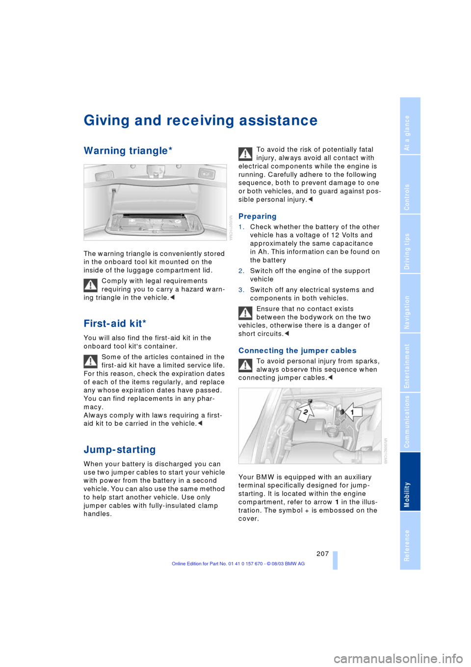
Your BMW is equipped with an auxiliary
terminal specifically designed for jump-
starting. It is located within the engine
compartment, refer to arrow 1 in the illus-
tration. The symbol + is embossed on the
cover.
Page 210 of 232
Giving and receiving assistance
208 1.Remove the cover of the BMW auxiliary
terminal for jump-starting
2.Connect one terminal clamp of the pos-
itive/+ jumper cable to the positive ter-
minal of the battery or an auxiliary ter-
minal for jump-starting of the vehicle
providing starting assistance
3.Connect the second terminal clamp of
the positive/+ jumper cable to the posi-
tive terminal of the battery or to an aux-
iliary terminal for jump-starting of the
vehicle to be started
On your BMW, there is a special nut as
body ground on the suspension strut
dome, refer to arrow 2 in the illustration.
4.Attach one end of the negative/Ð jumper
cable to the negative terminal of the
battery or to an engine or body ground
of the vehicle providing assistance
5.Connect the second terminal clamp of
the negative/Ð jumper cable to the neg-
ative terminal of the battery or to the
engine or body ground of the vehicle to
be started.
Starting the engine
1.Start the engine on the support vehicle
and allow it to run for several minutes
at a fast idle
2.Start the engine on the other vehicle in
the usual way.
If the first start attempt is not success-
ful, wait a few minutes before another
attempt in order to allow the discharged
battery to recharge
3.Allow the engines to run for several
minutes
4.Disconnect the jumper cables by
reversing the connection sequence.
If required, have the battery inspected and
recharged at your BMW center.
Never use spray fluids to start the
engine.<
Having vehicle towed
Always observe all applicable towing
laws and regulations.
Even if the transmission is in perfect work-
ing order, remember to disengage the
transmission lockout manually before tow-
ing the vehicle. Failure to observe this pre-
caution could result in automatic activation
of the transmission lockout while the vehi-
cle is being towed.<
Manual release of the transmission lockout,
refer to page 68.
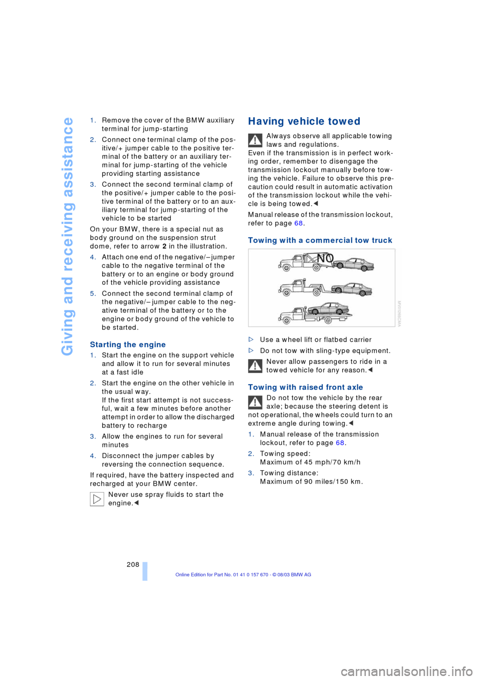
Towing with a commercial tow truck
>Use a wheel lift or flatbed carrier
>Do not tow with sling-type equipment.
Never allow passengers to ride in a
towed vehicle for any reason.<
Towing with raised front axle
Do not tow the vehicle by the rear
axle; because the steering detent is
not operational, the wheels could turn to an
extreme angle during towing.<
1.Manual release of the transmission
lockout, refer to page 68.
2.Towing speed:
Maximum of 45 mph/70 km/h
3.Towing distance:
Maximum of 90 miles/150 km.