child restraint BMW ACTIVE HYBRID 3 2014 F30H Owner's Manual
[x] Cancel search | Manufacturer: BMW, Model Year: 2014, Model line: ACTIVE HYBRID 3, Model: BMW ACTIVE HYBRID 3 2014 F30HPages: 247, PDF Size: 6.04 MB
Page 60 of 247
HintsOne person per safety belt
Never allow more than one person to
wear a single safety belt. Never allow infants or
small children to ride on a passenger's lap.◀
Putting on the belt
Lay the belt, without twisting, snugly
across the lap and shoulders, as close to the
body as possible. Make sure that the belt lies
low around the hips in the lap area and does
not press on the abdomen. Otherwise, the belt
can slip over the hips in a frontal impact and in‐
jure the abdomen.
The safety belt must not lie across the neck,
rub on sharp edges, be routed over breakable
objects, or be pinched.◀
What reduces the restraining effect
Avoid wearing bulky clothing, and pull
the shoulder belt periodically to readjust the
tension. Make sure that the belt is not jammed;
otherwise, the belt can be damaged and the
restraining effect is reduced.◀
Buckling the belt
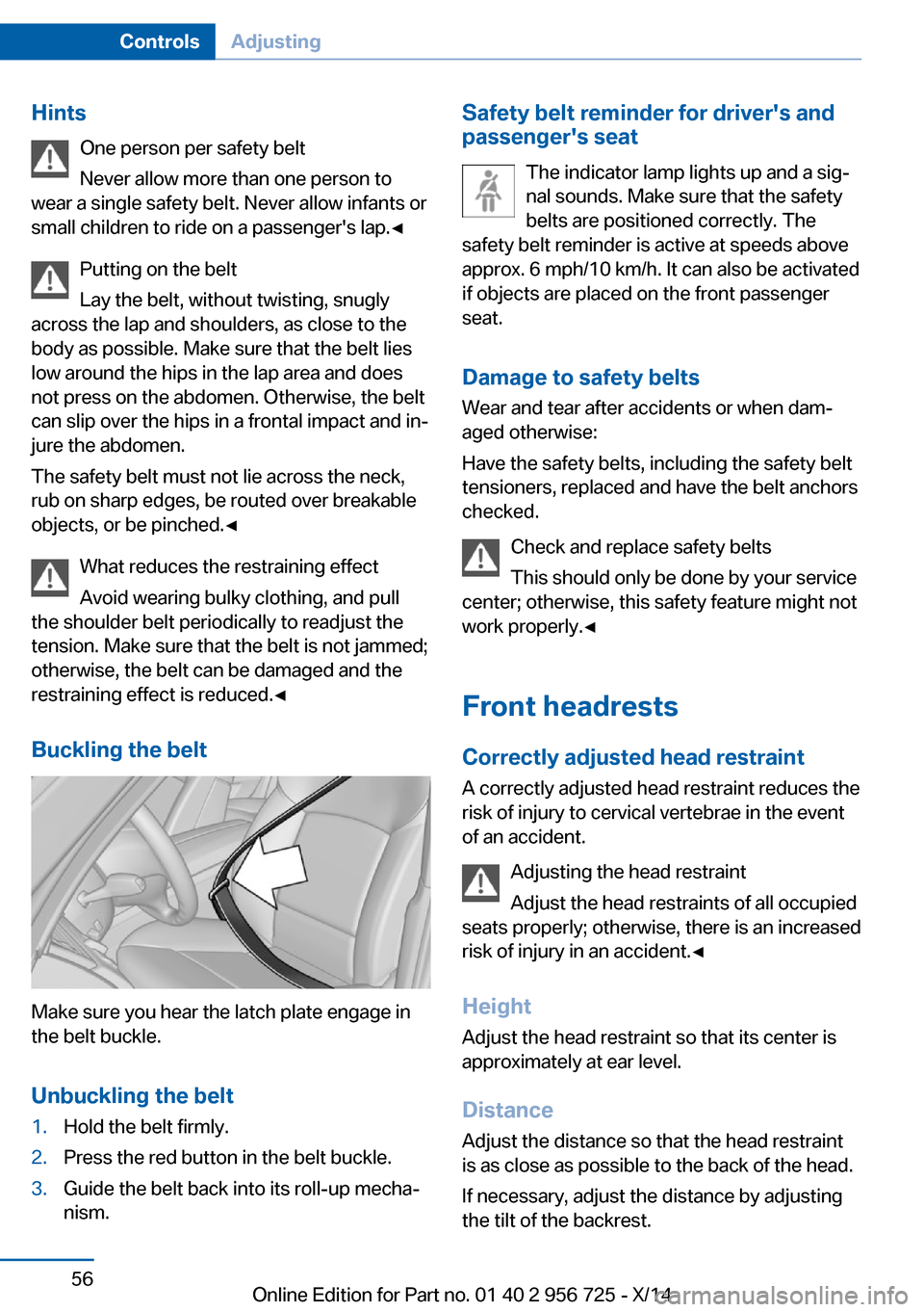
Make sure you hear the latch plate engage in
the belt buckle.
Unbuckling the belt
1.Hold the belt firmly.2.Press the red button in the belt buckle.3.Guide the belt back into its roll-up mecha‐
nism.Safety belt reminder for driver's and
passenger's seat
The indicator lamp lights up and a sig‐
nal sounds. Make sure that the safety
belts are positioned correctly. The
safety belt reminder is active at speeds above
approx. 6 mph/10 km/h. It can also be activated
if objects are placed on the front passenger
seat.
Damage to safety belts Wear and tear after accidents or when dam‐
aged otherwise:
Have the safety belts, including the safety belt
tensioners, replaced and have the belt anchors
checked.
Check and replace safety belts
This should only be done by your service
center; otherwise, this safety feature might not
work properly.◀
Front headrests Correctly adjusted head restraint
A correctly adjusted head restraint reduces the
risk of injury to cervical vertebrae in the event
of an accident.
Adjusting the head restraint
Adjust the head restraints of all occupied
seats properly; otherwise, there is an increased
risk of injury in an accident.◀
Height
Adjust the head restraint so that its center is
approximately at ear level.
Distance Adjust the distance so that the head restraint
is as close as possible to the back of the head.
If necessary, adjust the distance by adjusting
the tilt of the backrest.Seite 56ControlsAdjusting56
Online Edition for Part no. 01 40 2 956 725 - X/14
Page 66 of 247
Transporting children safelyVehicle features and optionsThis chapter describes all standard, country-
specific and optional features offered with the
series. It also describes features that are notnecessarily available in your car, e. g., due to
the selected options or country versions. This
also applies to safety-related functions and
systems.
The right place for children
Note
Children in the vehicle
Do not leave children unattended in the
vehicle; otherwise, they could endanger them‐
selves and other persons, e.g., by opening the
doors.◀
Children should always be in the rear Accident research shows that the safest place
for children is in the back seat.
Transporting children in the rear
Only transport children younger than
13 years of age or shorter than 5 ft/150 cm in
the rear in child restraint systems provided in
accordance with the age, weight and size of
the child; otherwise, there is an increased risk
of injury in an accident.
Children 13 years of age or older must wear a
safety belt as soon as a suitable child restraint
system can no longer be used due to their age,
weight and size.◀
Children on the front passenger seat
Should it ever be necessary to use a child re‐
straint system in the front passenger seat,
make sure that the front, knee and side airbags
on the front passenger side are deactivated.
Automatic deactivation of front-seat passen‐
ger airbags, refer to page 104.Note
Deactivating the front-seat passenger
airbags
If a child restraint system is used in the front
passenger seat, deactivate the front-seat pas‐
senger airbags; otherwise, there is an in‐
creased risk of injury to the child when the air‐
bags are activated, even with a child restraint
system.◀
Installing child restraint
systems
Hints Manufacturer's information for child re‐straint systems
To select, mount and use child restraint sys‐
tems, observe the information provided by the
system manufacturer; otherwise, the protec‐
tive effect can be lost.◀
Ensuring the stability of the child seat
When installing child restraint systems,
make sure that the child seat is securely fas‐
tened to the backrest of the seat. Angle and
headrest of the backrest might need to be ad‐
justed or possibly be removed. Make sure that
all backrests are securely locked. Otherwise
the stability of the child seat can be affected,
and there is an increased risk of injury becauseSeite 62ControlsTransporting children safely62
Online Edition for Part no. 01 40 2 956 725 - X/14
Page 67 of 247
of unexpected movement of the rear seat
backrest.◀
On the front passenger seat
Deactivating airbags Deactivating the front-seat passenger
airbags
If a child restraint system is used in the front
passenger seat, deactivate the front-seat pas‐
senger airbags; otherwise, there is an in‐
creased risk of injury to the child when the air‐
bags are activated, even with a child restraint
system.◀
After installing a child restraint system in the
front passenger seat, make sure that the front,
knee and side airbags on the front passenger
side are deactivated.
Deactivate the front-seat passenger airbags
automatically, refer to page 104.
Seat position and height
Before installing a child restraint system, move
the front passenger seat as far back as possi‐
ble and adjust its height to the highest and
thus best possible position for the belt and to
offer optimal protection in the event of an acci‐
dent.
If the upper anchorage of the safety belt is lo‐
cated in front of the belt guide of the child seat,
move the passenger seat carefully forward un‐
til the best possible belt guide position is
reached.
Backrest width Backrest width for the child seat
Before installing a child restraint system
in the front passenger seat, the backrest width
must be opened completely. Do not changethe adjustment after this; otherwise, the stabil‐
ity of the child seat will be reduced.◀
Adjustable backrest width: before installing a
child restraint system in the front passenger
seat, open the backrest width completely. Do
not change the backrest width again and do
not call up a memory position.
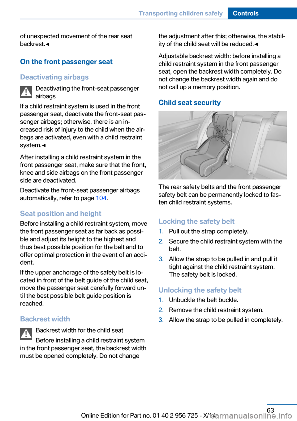
Child seat security
The rear safety belts and the front passenger
safety belt can be permanently locked to fas‐
ten child restraint systems.
Locking the safety belt
1.Pull out the strap completely.2.Secure the child restraint system with the
belt.3.Allow the strap to be pulled in and pull it
tight against the child restraint system.
The safety belt is locked.
Unlocking the safety belt
1.Unbuckle the belt buckle.2.Remove the child restraint system.3.Allow the strap to be pulled in completely.Seite 63Transporting children safelyControls63
Online Edition for Part no. 01 40 2 956 725 - X/14
Page 68 of 247
LATCH child restraint systemLATCH: Lower Anchors and Tether for Chil‐
dren.
Note Follow manufacturer's information for
LATCH child restraint systems
To mount and use the LATCH child restraint
systems, observe the operating and safety in‐
formation from the system manufacturer; oth‐
erwise, the level of protection may be re‐
duced.◀
Mounts for the lower LATCH anchors
The lower anchors may be used to attach the
CRS to the vehicle seat up to a combined child
and CRS weight of 65 lb/30 kg when the child
is restrained by the internal harnesses.
Properly engage the lower LATCH an‐
chors
Make sure that the lower LATCH anchors have
properly engaged and that the child restraint
system is resting snugly against the backrest; otherwise, the degree of protection may be re‐
duced.◀
Before mounting the LATCH child restraint
system, pull the belt away from the child re‐
straint system.
The corresponding symbol shows the
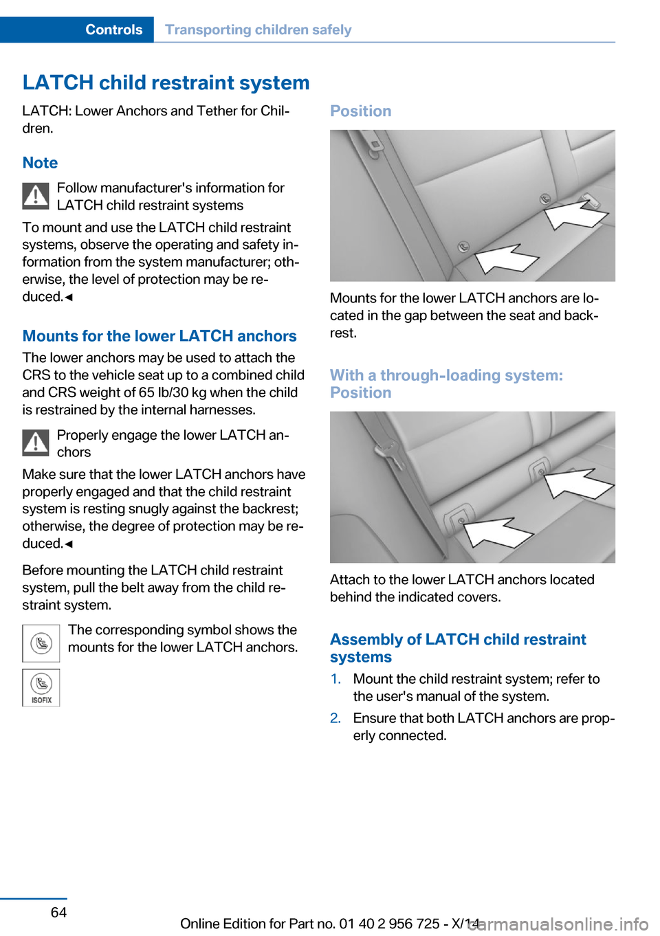
mounts for the lower LATCH anchors.Position
Mounts for the lower LATCH anchors are lo‐
cated in the gap between the seat and back‐
rest.
With a through-loading system:
Position
Attach to the lower LATCH anchors located
behind the indicated covers.
Assembly of LATCH child restraint
systems
1.Mount the child restraint system; refer to
the user's manual of the system.2.Ensure that both LATCH anchors are prop‐
erly connected.Seite 64ControlsTransporting children safely64
Online Edition for Part no. 01 40 2 956 725 - X/14
Page 69 of 247
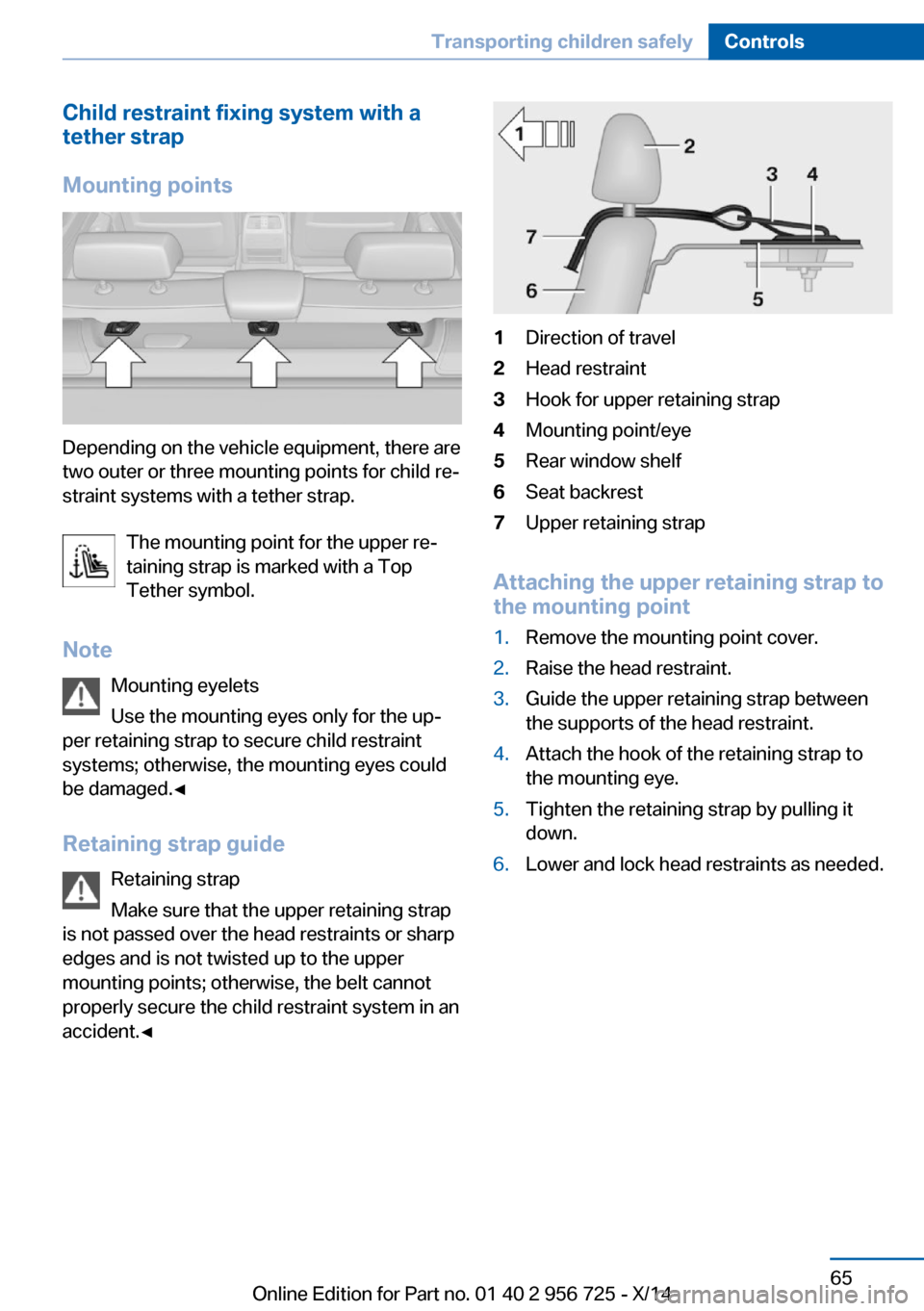
Child restraint fixing system with a
tether strap
Mounting points
Depending on the vehicle equipment, there are
two outer or three mounting points for child re‐
straint systems with a tether strap.
The mounting point for the upper re‐
taining strap is marked with a Top
Tether symbol.
Note Mounting eyelets
Use the mounting eyes only for the up‐
per retaining strap to secure child restraint
systems; otherwise, the mounting eyes could
be damaged.◀
Retaining strap guide Retaining strap
Make sure that the upper retaining strap
is not passed over the head restraints or sharp
edges and is not twisted up to the upper
mounting points; otherwise, the belt cannot
properly secure the child restraint system in an
accident.◀
1Direction of travel2Head restraint3Hook for upper retaining strap4Mounting point/eye5Rear window shelf6Seat backrest7Upper retaining strap
Attaching the upper retaining strap to
the mounting point
1.Remove the mounting point cover.2.Raise the head restraint.3.Guide the upper retaining strap between
the supports of the head restraint.4.Attach the hook of the retaining strap to
the mounting eye.5.Tighten the retaining strap by pulling it
down.6.Lower and lock head restraints as needed.Seite 65Transporting children safelyControls65
Online Edition for Part no. 01 40 2 956 725 - X/14
Page 108 of 247
Airbag system malfunctioning▷Warning lamp does not come on when the
ignition is turned on.▷The warning lamp lights up continuously.
In case of a malfunction have airbag sys‐
tem checked immediately.
In case of a malfunction have airbag system
checked immediately; otherwise, there is a risk
that the system does not function as expected
in case of a severe accident.◀
Automatic deactivation of the front-
seat passenger airbags
The system reads if the front passenger seat is
occupied by measuring the human body's re‐
sistance.
Front, knee and side airbag on the front pas‐
senger's side are either activated or deacti‐
vated.
Leave feet in the footwell
Make sure that the front passenger
keeps his or her feet in the footwell; otherwise,
proper functioning of the front passenger air‐
bag might not be assured.◀
Child restraint fixing system in the front
passenger seat
Before transporting a child on the front pas‐
senger seat, refer to the safety notes and in‐
structions for children on the front passenger
seat, see Children.◀
Malfunction of the automatic
deactivation system
When transporting older children and adults,
the front-seat passenger airbags may be deac‐
tivated in certain sitting positions. In this case,
the indicator lamp for the front-seat passenger
airbags lights up.
In this case, change the sitting position so that
the front-seat passenger airbags are activated
and the indicator lamp goes out.
If it is not possible to activate the airbags, have
the person sit in the rear.
To enable correct recognition of the occupied
seat cushion▷Do not attach covers, cushions, ball mats
or other items to the front passenger seat
unless they are specifically recommended
by your vehicle's manufacturer.▷Do not place any electronic devices on the
passenger seat if a child restraint system is
to be installed on it.▷Do not place objects under the seat that
could press against the seat from below.▷No moisture in or on the seat.
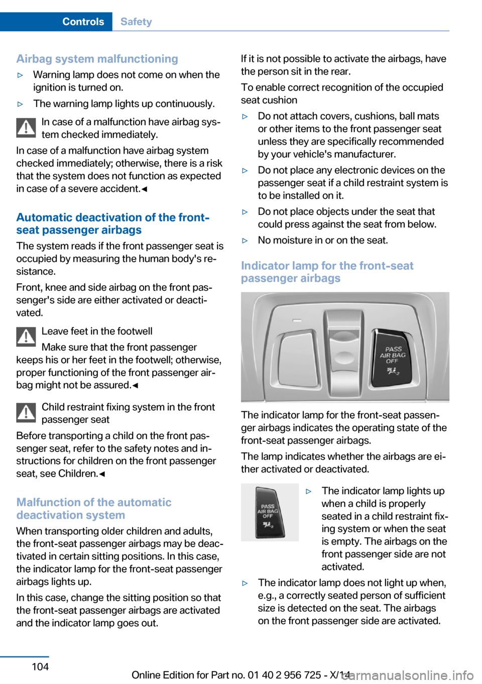
Indicator lamp for the front-seat
passenger airbags
The indicator lamp for the front-seat passen‐
ger airbags indicates the operating state of the
front-seat passenger airbags.
The lamp indicates whether the airbags are ei‐
ther activated or deactivated.
▷The indicator lamp lights up
when a child is properly
seated in a child restraint fix‐
ing system or when the seat
is empty. The airbags on the
front passenger side are not
activated.▷The indicator lamp does not light up when,
e.g., a correctly seated person of sufficient
size is detected on the seat. The airbags
on the front passenger side are activated.Seite 104ControlsSafety104
Online Edition for Part no. 01 40 2 956 725 - X/14
Page 166 of 247
▷Do not connect devices such as fans or
lights to the USB interface.▷Do not connect USB hard drives.▷Do not use the USB interface for recharg‐
ing external devices.
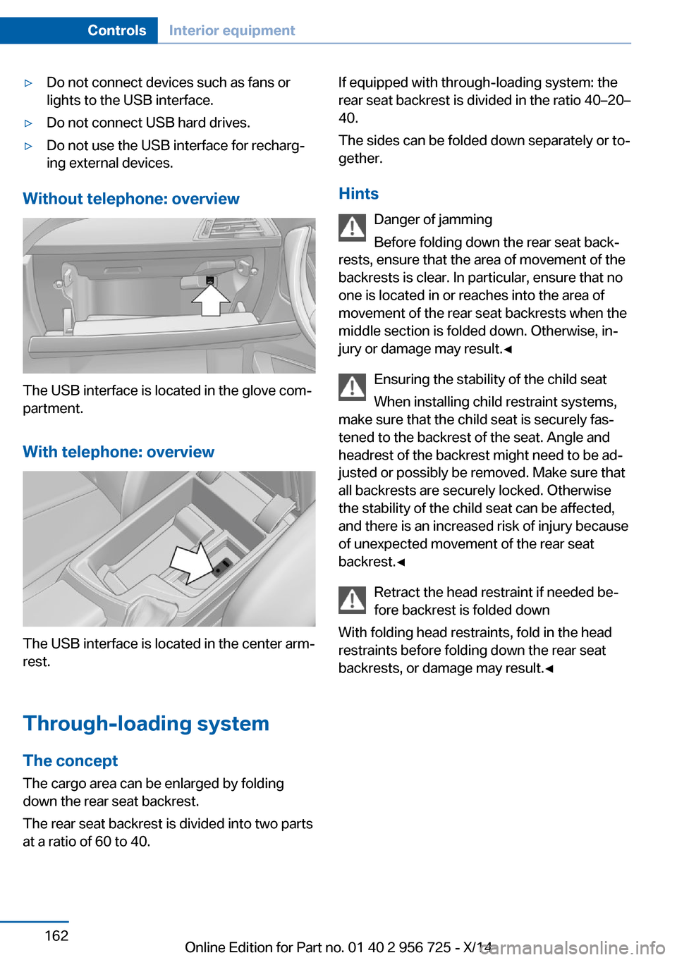
Without telephone: overview
The USB interface is located in the glove com‐
partment.
With telephone: overview
The USB interface is located in the center arm‐
rest.
Through-loading system The concept The cargo area can be enlarged by folding
down the rear seat backrest.
The rear seat backrest is divided into two parts at a ratio of 60 to 40.
If equipped with through-loading system: the
rear seat backrest is divided in the ratio 40–20–
40.
The sides can be folded down separately or to‐
gether.
Hints Danger of jamming
Before folding down the rear seat back‐
rests, ensure that the area of movement of the
backrests is clear. In particular, ensure that no
one is located in or reaches into the area of
movement of the rear seat backrests when the
middle section is folded down. Otherwise, in‐
jury or damage may result.◀
Ensuring the stability of the child seat
When installing child restraint systems,
make sure that the child seat is securely fas‐
tened to the backrest of the seat. Angle and
headrest of the backrest might need to be ad‐
justed or possibly be removed. Make sure that
all backrests are securely locked. Otherwise
the stability of the child seat can be affected,
and there is an increased risk of injury because
of unexpected movement of the rear seat
backrest.◀
Retract the head restraint if needed be‐
fore backrest is folded down
With folding head restraints, fold in the head
restraints before folding down the rear seat
backrests, or damage may result.◀Seite 162ControlsInterior equipment162
Online Edition for Part no. 01 40 2 956 725 - X/14
Page 237 of 247
BMW maintenance sys‐tem 204
Bonus range, ECO PRO 180
Bottle holder, refer to Cu‐ pholders 166
Brake assistant 124
Brake discs, break-in 170
Brake force display 122
Brake lights, adaptive 122
Brake lights, brake force dis‐ play 122
Brake pads, break-in 170
Braking, hints 173
Breakdown assis‐ tance 217, 218
Break-in 170
Brightness of Control Dis‐ play 95
Bulb replacement 206
Bulb replacement, front 207
Bulb replacement, halogen headlights 207
Bulb replacement, rear 212
Bulb replacement, xenon headlights 210
Bulbs and lights 206
Button, RES 132
Button, Start/Stop 67
Bypassing, refer to Jump- starting 218
C
California Proposition 65 Warning 8
Camera, care 226
Camera, rearview cam‐ era 140
Camera, Side View 143
Camera, Top View 144
Can holder, refer to Cuphold‐ ers 166
Car battery 215
Car care products 224
Care, displays 226
Care, vehicle 224 Cargo 175
Cargo area, enlarging 162
Cargo area, storage compart‐ ments 166
Cargo, securing 176
Cargo straps, securing cargo 176
Car key, refer to Remote con‐ trol 36
Carpet, care 226
Car wash 223
Catalytic converter, refer to Hot exhaust system 172
CBS Condition Based Serv‐ ice 204
CD/Multimedia, see user's manual for Navigation, En‐
tertainment and Communi‐
cation
Center armrest 165
Center console 16
Central locking system 41
Central screen, refer to Con‐ trol Display 18
Changes, technical, refer to Safety 7
Changing parts 206
Changing wheels 214
Changing wheels/tires 195
CHARGE, energy recov‐ ery 71
Charge indicator, high-volt‐ age battery 81
Chassis number, see vehicle identification number 10
Check Control 83
Checking the engine oil level electronically 200
Checking the oil level elec‐ tronically 200
Children, seating position 62
Children, transporting safely 62
Child restraint fixing sys‐ tem 62 Child restraint fixing system
LATCH 64
Child restraint fixing systems, mounting 62
Child safety locks 66
Child seat, mounting 62
Child seats 62
Chrome parts, care 225
Cigarette lighter 160
Cleaning displays 226
Climate control 150
Clock 87
Closing/opening via door lock 41
Closing/opening with remote control 39
Clothes hooks 166
Coasting 70
Cockpit 14
Combination reel, refer to Turn signals 72
Combination reel, refer to Wiper system 73
Combustion engine, start‐ ing 68
Comfort Access 43
COMFORT program, Dy‐ namic Driving Control 127
Compartments in the doors 165
Compass 158
Computer 91
Condensation on win‐ dows 152
Condensation under the vehi‐ cle 174
Condition Based Service CBS 204
Confirmation signal 45
ConnectedDrive, see user's manual for Navigation, En‐
tertainment and Communi‐
cation
ConnectedDrive Services
Connecting electrical devi‐ ces 160 Seite 233Everything from A to ZReference233
Online Edition for Part no. 01 40 2 956 725 - X/14
Page 240 of 247
Height, vehicle 230
High-beam Assistant 99
High beams 73
High beams/low beams, refer to High-beam Assistant 99
High-voltage battery, charge indicator 81
High-voltage battery, dis‐ charge 171
Hills 173
Hill start assistant, refer to Drive-off assistant 128
Hints 6
Holder for beverages 166
Hood 199
Horn 14
Hotel function, trunk lid 42
Hot exhaust system 172
HUD Head-up Display 95
Hybrid system, adapting to the course of the road 83
Hybrid system, at a glance 31
Hybrid system, automatic de‐ activation 222
Hybrid system, contact with water 222
Hybrid system, displays 81
Hybrid system, safety 221
Hydroplaning 172
I Ice warning, see External temperature warning 87
Icy roads, see External tem‐ perature warning 87
Identification marks, tires 192
Identification number, see ve‐ hicle identification num‐
ber 10
iDrive 18
Ignition key, refer to Remote control 36
Ignition off 67
Ignition on 67 Indication of a flat
tire 106 , 109
Indicator and alarm lamps, see Check Control 83
Indicator lamp, see Check Control 83
Individual air distribution 152
Individual settings, refer to Personal Profile 37
Inflation pressure, tires 190
Inflation pressure warning FTM, tires 109
Info display, refer to Com‐ puter 91
Initialize, Tire Pressure Moni‐ tor TPM 106
Initializing, Flat Tire Monitor FTM 109
Instrument cluster 80
Instrument cluster, electronic displays 80
Instrument lighting 100
Integrated key 36
Integrated Owner's Manual in the vehicle 29
Intelligent Emergency Re‐ quest 217
Intelligent Safety 110
Intensity, AUTO pro‐ gram 151
Interior equipment 156
Interior lights 100
Interior lights via remote con‐ trol 39
Interior motion sensor 47
Interior rearview mirror, auto‐ matic dimming feature 61
Interior rearview mirror, com‐ pass 158
Interior rearview mirror, man‐ ually dimmable 61
Interval display, service re‐ quirements 88 J
Jacking points for the vehicle jack 214
Joystick, Steptronic transmis‐ sion 76
Jump-starting 218
K
Key/remote control 36
Keyless Go, refer to Comfort Access 43
Key Memory, refer to Per‐ sonal Profile 37
Kickdown, Steptronic trans‐ mission 76
Knee airbag 103
L Lamp replacement 206
Lamp replacement, front 207
Lamp replacement, rear 212
Lane departure warning 119
Lane margin, warning 119
Language on Control Dis‐ play 94
Lashing eyes, securing cargo 176
LATCH child restraint sys‐ tem 64
Launch Control 78
Leather, care 224
LEDs, light-emitting di‐ odes 207
Length, vehicle 230
Letters and numbers, enter‐ ing 25
Light alloy wheels, care 225
Light control 98
Light-emitting diodes, LEDs 207
Lighter 160
Lighting 97 Seite 236ReferenceEverything from A to Z236
Online Edition for Part no. 01 40 2 956 725 - X/14
Page 241 of 247
Lighting via remote con‐trol 39
Light reel 97
Lights 97
Lights and bulbs 206
Load 176
Loading 175
Lock, door 41
Locking/unlocking via door lock 41
Locking/unlocking with re‐ mote control 39
Locking, automatic 45
Locking, settings 45
Locking via trunk lid 42
Lock, power window 49
Locks, doors, and win‐ dows 66
Low beams 97
Low beams, automatic, refer to High-beam Assistant 99
Lower back support 54
Luggage rack, see Roof- mounted luggage rack 177
Lumbar support 54
M
Maintenance 204
Maintenance require‐ ments 204
Maintenance, service require‐ ments 88
Maintenance system, BMW 204
Make-up mirror 160
Malfunction displays, see Check Control 83
Manual air distribution 152
Manual air flow 152
Manual mode, Steptronic transmission 77
Manual operation, door lock 41
Manual operation, exterior mirrors 60 Manual operation, fuel filler
flap 186
Manual operation, Park Dis‐ tance Control PDC 138
Manual operation, rearview camera 141
Manual operation, Side View 143
Manual operation, Top View 144
Marking on approved tires 195
Marking, run-flat tires 196
Master key, refer to Remote control 36
Maximum cooling 151
Maximum speed, display 89
Maximum speed, winter tires 196
Measure, units of 95
Medical kit 218
Memory, seat, mirror 58
Menu in instrument clus‐ ter 91
Menus, operating, iDrive 18
Menus, refer to iDrive operat‐ ing concept 20
Messages, see Check Con‐ trol 83
Microfilter 153
Minimum tread, tires 194
Mirror 59
Mirror memory 58
Mobile communication devi‐ ces in the vehicle 172
Modifications, technical, refer to Safety 7
Moisture in headlight 207
Monitor, refer to Control Dis‐ play 18
Mounting of child restraint systems 62
Multifunction steering wheel, buttons 14 N
Navigation, see user's manual for Navigation, Entertain‐
ment and Communication
Neck restraints, front, refer to Head restraints 56
Neck restraints, rear, refer to Head restraints 57
Neutral cleaner, see wheel cleaner 225
New wheels and tires 195
Nylon rope for tow-starting/ towing 220
O OBD Onboard Diagnosis 204
OBD, see OBD Onboard Di‐ agnosis 204
Obstacle marking, rearview camera 141
Octane rating, refer to Rec‐ ommended fuel grade 188
Odometer 87
Office, see user's manual for Navigation, Entertainment
and Communication
Officially use hybrid sys‐ tem 170
Oil 200
Oil, adding 201
Oil additives 201
Oil change 202
Oil change interval, service requirements 88
Oil filler neck 201
Oil types, alternative 202
Oil types, approved 202
Old batteries, disposal 215
Onboard monitor, refer to Control Display 18
Onboard vehicle tool kit 206
Opening/closing via door lock 41
Opening and closing 36 Seite 237Everything from A to ZReference237
Online Edition for Part no. 01 40 2 956 725 - X/14