tow BMW ACTIVE HYBRID 3 2015 F30H User Guide
[x] Cancel search | Manufacturer: BMW, Model Year: 2015, Model line: ACTIVE HYBRID 3, Model: BMW ACTIVE HYBRID 3 2015 F30HPages: 251, PDF Size: 5.49 MB
Page 120 of 251
The automatic braking intervention is executed
with limited braking force and for a brief period
only.
If the vehicle is equipped with Active Cruise
Control with Stop & Go, the front-end collision
warning is controlled via the cruise control ra‐
dar sensor.
The front-end collision warning is available
even if cruise control has been deactivated.
With the vehicle approaching another vehicle
intentionally the collision warning is delayed
avoiding false alarm.
General information
The system issues a two-phase warning of a
possible danger of collision with vehicles at
speeds above approx. 3 mph/5 km/h. Time of
warnings may vary with the current driving sit‐
uation.
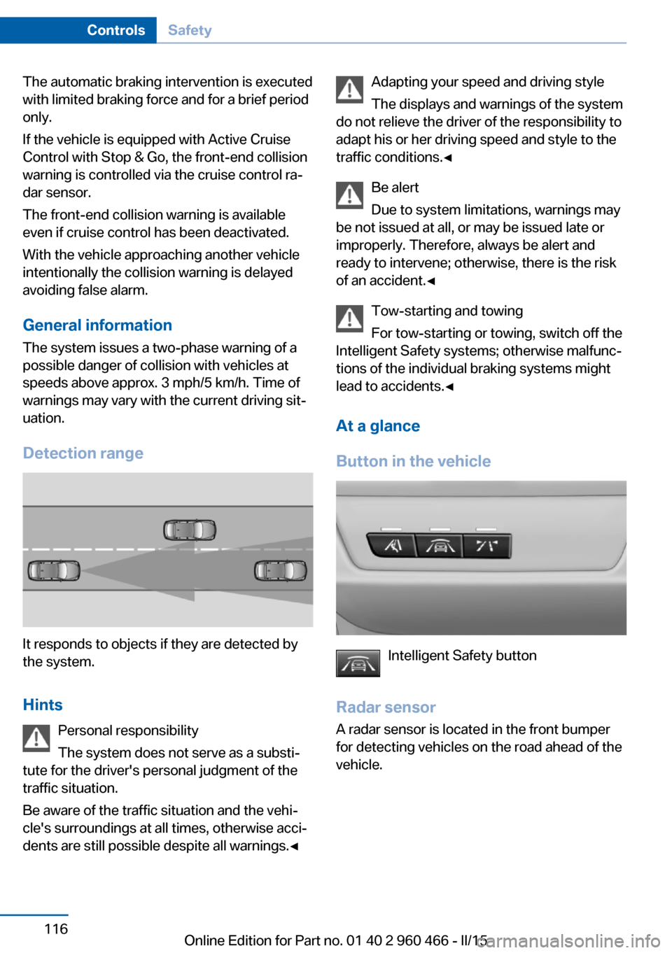
Detection range
It responds to objects if they are detected by
the system.
Hints Personal responsibility
The system does not serve as a substi‐
tute for the driver's personal judgment of the
traffic situation.
Be aware of the traffic situation and the vehi‐
cle's surroundings at all times, otherwise acci‐
dents are still possible despite all warnings.◀
Adapting your speed and driving style
The displays and warnings of the system
do not relieve the driver of the responsibility to
adapt his or her driving speed and style to the
traffic conditions.◀
Be alert
Due to system limitations, warnings may
be not issued at all, or may be issued late or
improperly. Therefore, always be alert and
ready to intervene; otherwise, there is the risk
of an accident.◀
Tow-starting and towing
For tow-starting or towing, switch off the
Intelligent Safety systems; otherwise malfunc‐
tions of the individual braking systems might
lead to accidents.◀
At a glance
Button in the vehicle
Intelligent Safety button
Radar sensor
A radar sensor is located in the front bumper
for detecting vehicles on the road ahead of the
vehicle.
Seite 116ControlsSafety116
Online Edition for Part no. 01 40 2 960 466 - II/15
Page 123 of 251
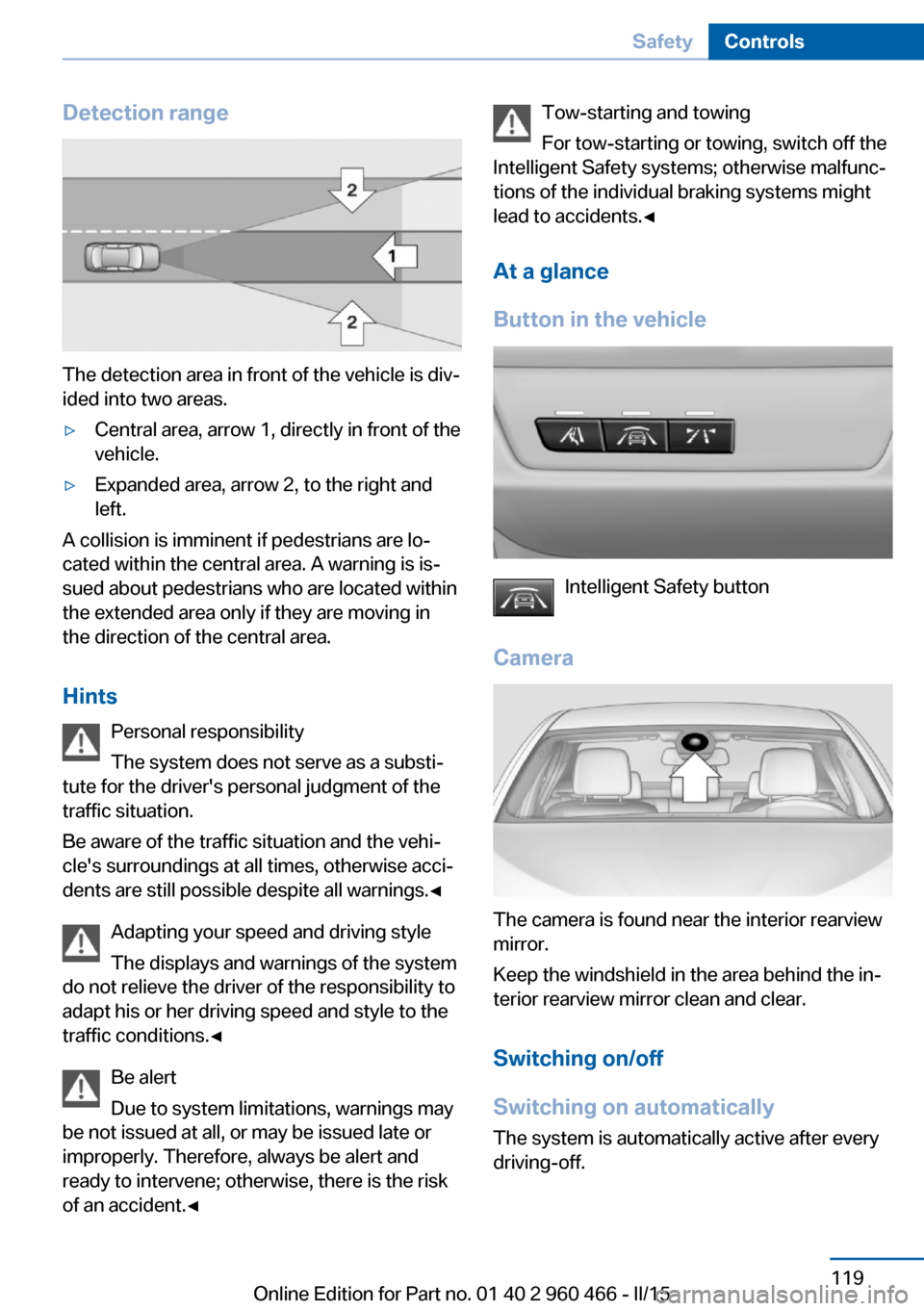
Detection range
The detection area in front of the vehicle is div‐
ided into two areas.
▷Central area, arrow 1, directly in front of the
vehicle.▷Expanded area, arrow 2, to the right and
left.
A collision is imminent if pedestrians are lo‐
cated within the central area. A warning is is‐
sued about pedestrians who are located within
the extended area only if they are moving in
the direction of the central area.
Hints Personal responsibility
The system does not serve as a substi‐
tute for the driver's personal judgment of the
traffic situation.
Be aware of the traffic situation and the vehi‐
cle's surroundings at all times, otherwise acci‐
dents are still possible despite all warnings.◀
Adapting your speed and driving style
The displays and warnings of the system
do not relieve the driver of the responsibility to
adapt his or her driving speed and style to the
traffic conditions.◀
Be alert
Due to system limitations, warnings may
be not issued at all, or may be issued late or
improperly. Therefore, always be alert and
ready to intervene; otherwise, there is the risk
of an accident.◀
Tow-starting and towing
For tow-starting or towing, switch off the
Intelligent Safety systems; otherwise malfunc‐
tions of the individual braking systems might
lead to accidents.◀
At a glance
Button in the vehicle
Intelligent Safety button
Camera
The camera is found near the interior rearview
mirror.
Keep the windshield in the area behind the in‐
terior rearview mirror clean and clear.
Switching on/off
Switching on automatically The system is automatically active after every
driving-off.
Seite 119SafetyControls119
Online Edition for Part no. 01 40 2 960 466 - II/15
Page 126 of 251
▷When using the turn signal.
System limits
The system may not be fully functional in the
following situations:
▷In heavy fog, rain or snowfall.▷In the event of missing, worn, poorly visi‐
ble, merging, diverging, or multiple lane
markings such as in construction areas.▷When lane markings are covered in snow,
ice, dirt or water.▷In tight curves or on narrow lanes.▷When the lane markings are covered by
objects.▷When driving very close to the vehicle in
front of you.▷When driving toward bright lights.▷When the windshield in front of the interior
rearview mirror is fogged over, dirty or cov‐
ered with stickers, etc.▷During calibration of the camera immedi‐
ately after vehicle shipment.
Active Blind Spot Detection
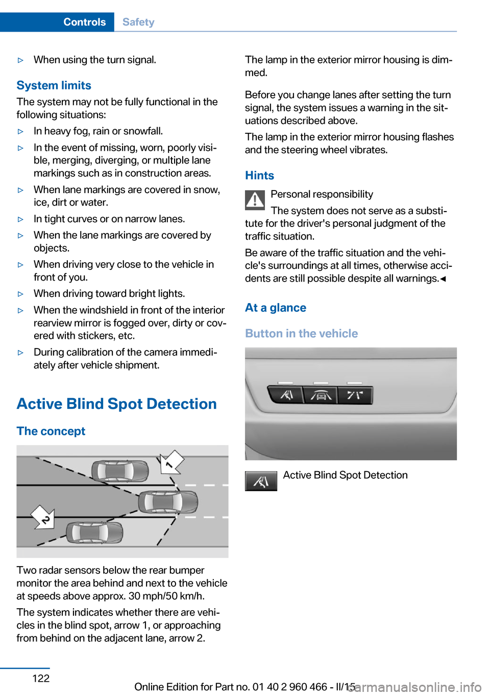
The concept
Two radar sensors below the rear bumper
monitor the area behind and next to the vehicle
at speeds above approx. 30 mph/50 km/h.
The system indicates whether there are vehi‐
cles in the blind spot, arrow 1, or approaching
from behind on the adjacent lane, arrow 2.
The lamp in the exterior mirror housing is dim‐
med.
Before you change lanes after setting the turn
signal, the system issues a warning in the sit‐
uations described above.
The lamp in the exterior mirror housing flashes
and the steering wheel vibrates.
Hints Personal responsibility
The system does not serve as a substi‐
tute for the driver's personal judgment of the
traffic situation.
Be aware of the traffic situation and the vehi‐
cle's surroundings at all times, otherwise acci‐
dents are still possible despite all warnings.◀
At a glance
Button in the vehicle
Active Blind Spot Detection
Seite 122ControlsSafety122
Online Edition for Part no. 01 40 2 960 466 - II/15
Page 144 of 251
Settings are stored for the profile currently in
use.
Visual warning
The approach of the vehicle to an object can
be shown on the Control Display. Objects that
are farther away are already displayed on the
Control Display before a signal sounds.
A display appears as soon as Park Distance
Control (PDC) is activated.
The range of the sensors is represented in the
colors green, yellow and red.
When the image of the rearview camera is dis‐
played, the reel can be made to PDC:
"Rear view camera"
System limits
Limits of ultrasonic measurement
Ultrasonic measuring might not function under
the following circumstances:
▷For small children and animals.▷For persons with certain clothing, e.g.
coats.▷With external interference of the ultra‐
sound, e.g. from passing vehicles or loud
machines.▷When sensors are dirty, iced over, dam‐
aged or out of position.▷Under certain weather conditions such as
high relative humidity, rain, snowfall, ex‐
treme heat or strong wind.▷With tow bars and trailer couplings of other
vehicles.▷With thin or wedge-shaped objects.▷With moving objects.▷With elevated, protruding objects such as
ledges or cargo.▷With objects with corners and sharp edges.▷With objects with a fine surface structure
such as fences.▷For objects with porous surfaces.
Low objects already displayed, e.g., curbs, can
move into the blind area of the sensors before
or after a continuous tone sounds.
False warnings
PDC may issue a warning under the following conditions even though there is no obstacle
within the detection range:
▷In heavy rain.▷When sensors are very dirty or covered
with ice.▷When sensors are covered in snow.▷On rough road surfaces.▷On uneven surfaces, such as speed
bumps.▷In large buildings with right angles and
smooth walls, e.g., in underground ga‐
rages.▷In automatic car washes.▷Through heavy pollution.▷Due to other ultrasound sources, e.g.,
sweeping machines, high pressure steam
cleaners or neon lights.
The malfunction is signaled by a continu‐
ous tone alternating between the front and
rear speakers. As soon as the malfunction
due to other ultrasound sources is no lon‐
ger present, the system is again fully func‐
tional.
Malfunction
A Check Control message is displayed.
The range of the sensors is shown as a shaded
area on the Control Display.
PDC has failed. Have the system checked.
To ensure full functionality:
▷Keep the sensors clean and free of ice.▷dimmedDo not put any stickers on sen‐
sors.Seite 140ControlsDriving comfort140
Online Edition for Part no. 01 40 2 960 466 - II/15
Page 154 of 251
▷For small children and animals.▷For persons with certain clothing, e.g.
coats.▷With external interference of the ultra‐
sound, e.g. from passing vehicles or loud
machines.▷When sensors are dirty, iced over, dam‐
aged or out of position.▷Under certain weather conditions such as
high relative humidity, rain, snowfall, ex‐
treme heat or strong wind.▷With tow bars and trailer couplings of other
vehicles.▷With thin or wedge-shaped objects.▷With moving objects.▷With elevated, protruding objects such as
ledges or cargo.▷With objects with corners and sharp edges.▷With objects with a fine surface structure
such as fences.▷For objects with porous surfaces.
Low objects already displayed, e.g., curbs, can
move into the blind area of the sensors before
or after a continuous tone sounds.
The parking assistant may identify parking
spaces that are not suitable for parking.
Malfunction
A Check Control message is displayed.
The parking assistant failed. Have the system
checked.
Seite 150ControlsDriving comfort150
Online Edition for Part no. 01 40 2 960 466 - II/15
Page 158 of 251
Switching on
Press any button except▷Rear window defroster.▷Seat heating.
Microfilter/activated-charcoal filter
In external and recirculated air mode the mi‐
crofilter/activated charcoal filter filters dust,
pollen, and gaseous pollutants out of the air.
This filter should be replaced during scheduled
maintenance, refer to page 209, of your vehi‐
cle.
Ventilation
Front ventilation
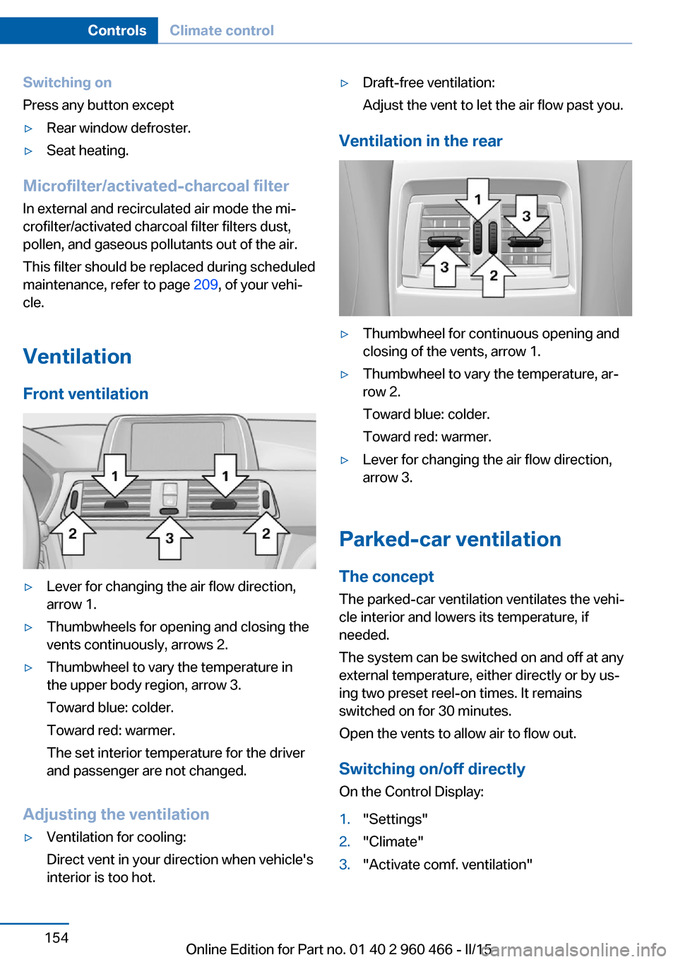
▷Lever for changing the air flow direction,
arrow 1.▷Thumbwheels for opening and closing the
vents continuously, arrows 2.▷Thumbwheel to vary the temperature in
the upper body region, arrow 3.
Toward blue: colder.
Toward red: warmer.
The set interior temperature for the driver
and passenger are not changed.
Adjusting the ventilation
▷Ventilation for cooling:
Direct vent in your direction when vehicle's
interior is too hot.▷Draft-free ventilation:
Adjust the vent to let the air flow past you.
Ventilation in the rear
▷Thumbwheel for continuous opening and
closing of the vents, arrow 1.▷Thumbwheel to vary the temperature, ar‐
row 2.
Toward blue: colder.
Toward red: warmer.▷Lever for changing the air flow direction,
arrow 3.
Parked-car ventilation
The concept The parked-car ventilation ventilates the vehi‐
cle interior and lowers its temperature, if
needed.
The system can be switched on and off at any
external temperature, either directly or by us‐
ing two preset reel-on times. It remains
switched on for 30 minutes.
Open the vents to allow air to flow out.
Switching on/off directly
On the Control Display:
1."Settings"2."Climate"3."Activate comf. ventilation"Seite 154ControlsClimate control154
Online Edition for Part no. 01 40 2 960 466 - II/15
Page 169 of 251
Storage compartmentsVehicle features and optionsThis chapter describes all standard, country-
specific and optional features offered with the
series. It also describes features that are not
necessarily available in your car, e. g., due to
the selected options or country versions. This
also applies to safety-related functions and
systems. The respectively applicable country
provisions must be observed when using the
respective features and systems.
Hints No loose objects in the car's interior
Do not stow any objects in the car's inte‐
rior without securing them; otherwise, they
may present a danger to occupants e.g., during
braking and evasive maneuvers.◀
Do not place anti-slip mats on the dash‐
board
Do not place anti-slip mats on the dashboard.
The mat materials could damage the dash‐
board.◀
Storage compartments The following storage compartments are avail‐
able in the vehicle interior:▷Glove compartment on the front passenger
side, refer to page 165.▷Glove compartment on the driver's side,
refer to page 166.▷Without Smoker's package: Front storage
compartment, in front of the cupholders,
refer to page 166.▷Storage compartment in the front center
armrest, refer to page 166.▷Compartments in the doors, refer to
page 166.▷Nets on the backrests of the front seats.
Glove compartment
Front passenger side
Note Close the glove compartment again im‐
mediately
Close the glove compartment immediately af‐
ter use while driving; otherwise, injury may oc‐
cur during accidents.◀
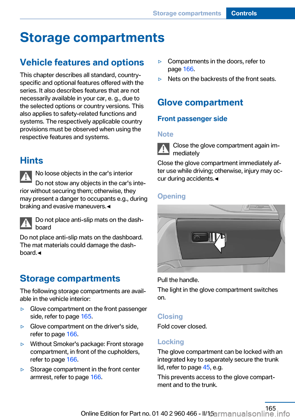
Opening
Pull the handle.
The light in the glove compartment switches
on.
ClosingFold cover closed.
Locking
The glove compartment can be locked with an
integrated key to separately secure the trunk
lid, refer to page 45, e.g.
This prevents access to the glove compart‐
ment and to the trunk.
Seite 165Storage compartmentsControls165
Online Edition for Part no. 01 40 2 960 466 - II/15
Page 170 of 251
After the glove compartment is locked, the re‐
mote control can be handed over, such as at a
hotel, without the integrated key.
Driver's side
Note Close the glove compartment again im‐
mediately
Close the glove compartment immediately af‐
ter use while driving; otherwise, injury may oc‐
cur during accidents.◀
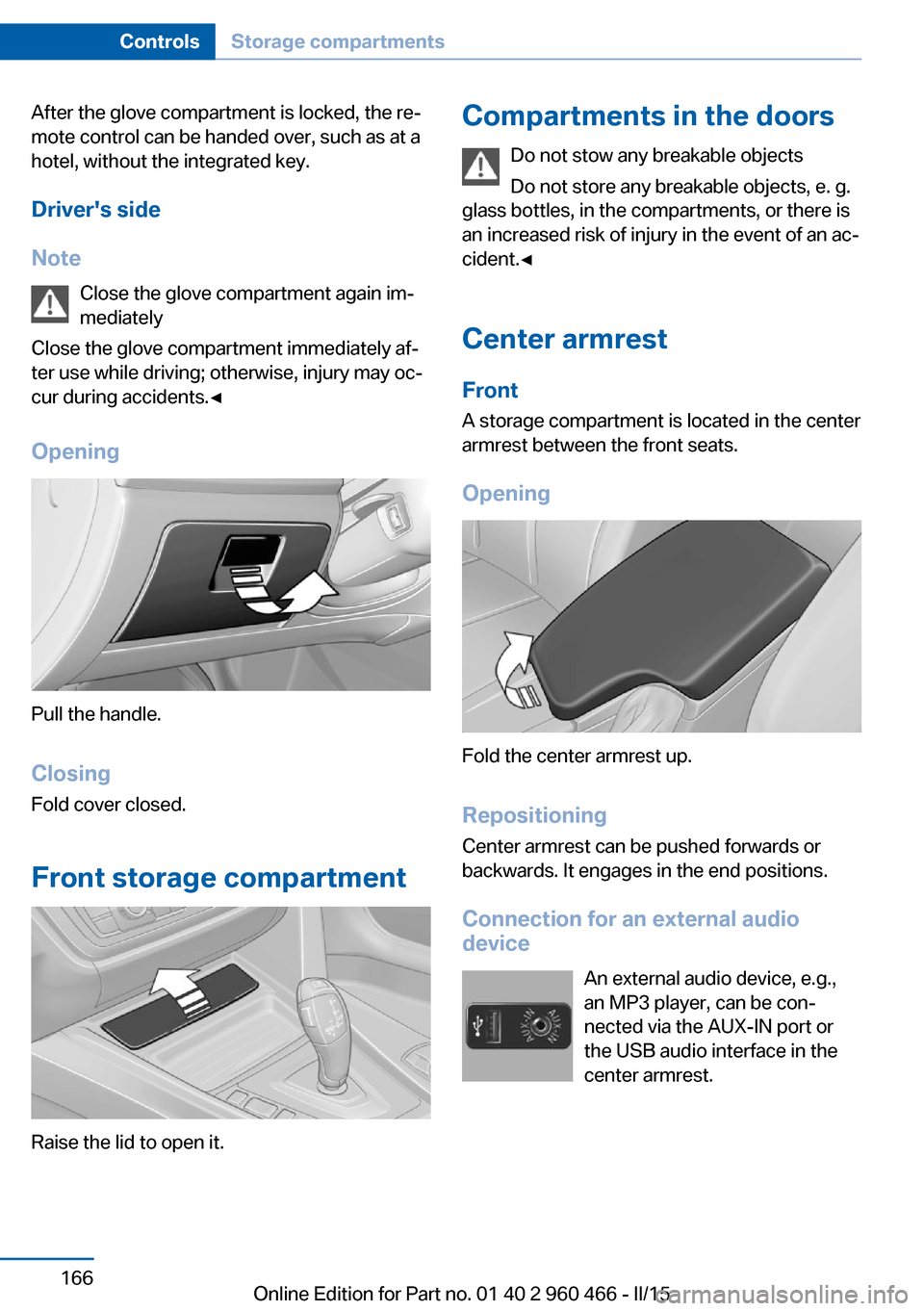
Opening
Pull the handle.
ClosingFold cover closed.
Front storage compartment
Raise the lid to open it.
Compartments in the doors Do not stow any breakable objects
Do not store any breakable objects, e. g.
glass bottles, in the compartments, or there is
an increased risk of injury in the event of an ac‐
cident.◀
Center armrest
Front
A storage compartment is located in the center
armrest between the front seats.
Opening
Fold the center armrest up.
Repositioning
Center armrest can be pushed forwards or
backwards. It engages in the end positions.
Connection for an external audio
device
An external audio device, e.g.,
an MP3 player, can be con‐
nected via the AUX-IN port or
the USB audio interface in the
center armrest.
Seite 166ControlsStorage compartments166
Online Edition for Part no. 01 40 2 960 466 - II/15
Page 171 of 251
Cupholders
Hints Shatter-proof containers and no hot
drinks
Use light and shatter-proof containers and do
not transport hot drinks. Otherwise, there is the increased danger of injury in an accident.◀
Unsuitable containers
Do not forcefully push unsuitable con‐
tainers into the cupholders. This may result in
damage.◀
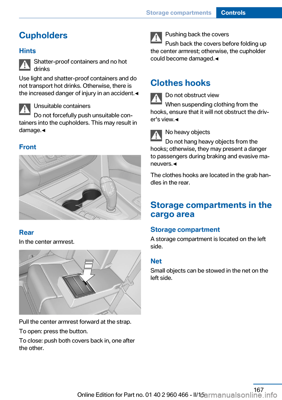
Front
Rear
In the center armrest.
Pull the center armrest forward at the strap.
To open: press the button.
To close: push both covers back in, one after
the other.
Pushing back the covers
Push back the covers before folding up
the center armrest; otherwise, the cupholder
could become damaged.◀
Clothes hooks Do not obstruct view
When suspending clothing from the
hooks, ensure that it will not obstruct the driv‐
er's view.◀
No heavy objects
Do not hang heavy objects from the
hooks; otherwise, they may present a danger
to passengers during braking and evasive ma‐
neuvers.◀
The clothes hooks are located in the grab han‐
dles in the rear.
Storage compartments in the
cargo area
Storage compartment A storage compartment is located on the left
side.
Net
Small objects can be stowed in the net on the
left side.Seite 167Storage compartmentsControls167
Online Edition for Part no. 01 40 2 960 466 - II/15
Page 181 of 251
LoadingVehicle features and options
This chapter describes all standard, country-
specific and optional features offered with the
series. It also describes features that are not
necessarily available in your car, e. g., due to
the selected options or country versions. This
also applies to safety-related functions and
systems. The respectively applicable country
provisions must be observed when using the
respective features and systems.
Hints Overloading the vehicle
To avoid exceeding the approved ca‐
pacity of the tires, never overload the vehicle.
Overloading can lead to overheating and in‐
creases the rate at which damage develops in‐
side the tires. This could result in a sudden
loss of tire inflation pressure.◀
No fluids in the cargo area
Make sure that fluids do not leak into the
cargo area; otherwise, the vehicle may be dam‐
aged.◀
Heavy and hard objects
Do not stow any heavy and hard objects
in the car's interior without securing them; oth‐
erwise, they may present a danger to occu‐
pants, e.g., during braking and evasive maneu‐
vers.◀
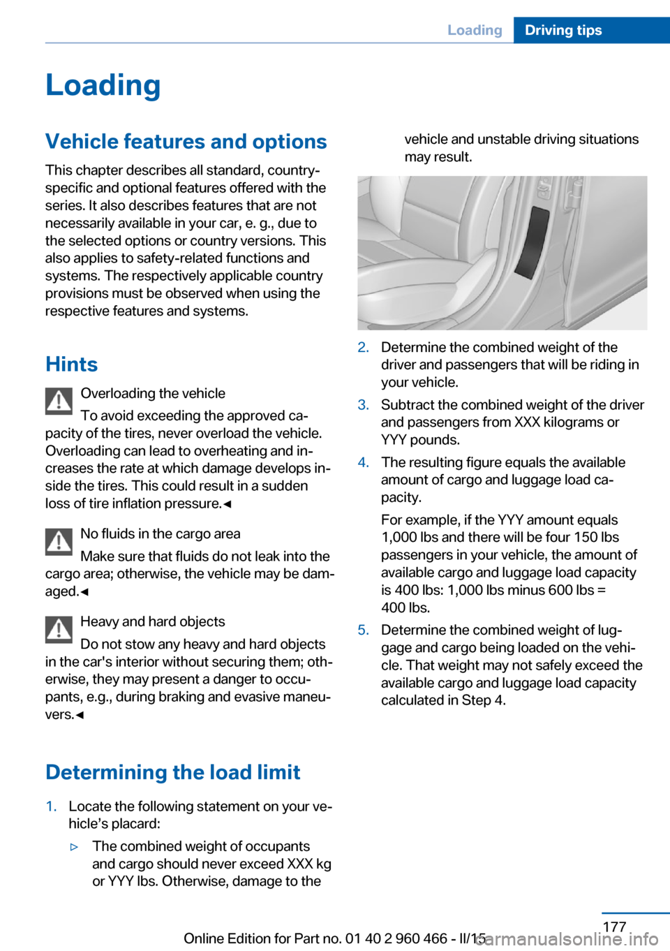
Determining the load limit1.Locate the following statement on your ve‐
hicle’s placard:▷The combined weight of occupants
and cargo should never exceed XXX kg
or YYY lbs. Otherwise, damage to thevehicle and unstable driving situations
may result.2.Determine the combined weight of the
driver and passengers that will be riding in
your vehicle.3.Subtract the combined weight of the driver
and passengers from XXX kilograms or
YYY pounds.4.The resulting figure equals the available
amount of cargo and luggage load ca‐
pacity.
For example, if the YYY amount equals
1,000 lbs and there will be four 150 lbs
passengers in your vehicle, the amount of
available cargo and luggage load capacity
is 400 lbs: 1,000 lbs minus 600 lbs =
400 lbs.5.Determine the combined weight of lug‐
gage and cargo being loaded on the vehi‐
cle. That weight may not safely exceed the
available cargo and luggage load capacity
calculated in Step 4.Seite 177LoadingDriving tips177
Online Edition for Part no. 01 40 2 960 466 - II/15