change wheel BMW ACTIVE HYBRID 3 2015 F30H Owner's Manual
[x] Cancel search | Manufacturer: BMW, Model Year: 2015, Model line: ACTIVE HYBRID 3, Model: BMW ACTIVE HYBRID 3 2015 F30HPages: 251, PDF Size: 5.49 MB
Page 6 of 251
Addendum
thereof: “BMW recommends that you have
the maintenance carried out by your service
center.”
10. At page 192, under the heading “Tire infla-
tion specifications,” the sentence begin-
ning, “Tire inflation pressure specifications
apply to approved tire sizes …” should be
disregarded.
11. At page 197, under the heading: “Mount-
ing,” the paragraph beginning, “Have
mounting and balancing …” should be dis-
regarded and the following text should be
read in lieu thereof: “BMW recommends
that you have mounting and balancing per-
formed by your service center or a tire
mounting specialist.”
12. At page 197, under the heading: “Approved
wheels and tires,” the term “Approved”
should be disregarded and in lieu thereof,
the term “Recommended” should be read
in its place. In addition, the text of that sec-
tion should be disregarded and the follow-
ing text should be read in lieu thereof:
The manufacturer of your vehicle strongly
suggests that you use wheels and tires that
have been recommended by the vehicle
manufacturer for your vehicle type; other-
wise, for example, despite having the same
official size ratings, variations can lead to
body contact and with it, the risk of severe
accidents.
The manufacturer of your vehicle does not
evaluate non-recommended wheels and
tires to determine if they are suitable for use
on your vehicle.
13. At page 202, under the heading: “Snow
Chains,” the text should be disregarded and
the following text should be read in lieu
thereof:
Only certain types of fine-link snow chains
have been tested by the manufacturer of
your vehicle and are determined by the
manufacturer of your vehicle to be road safe
and are recommended by the manufacturer
of your vehicle.
Information about recommended snow
chains is available from a service center.
14. At page 204, under the heading “Hood,” the
sentence beginning, “If you are unfamiliar”
should be disregarded.
15. At page 207, under the heading: “Engine Oil
Change,” the text should be disregarded
and in lieu thereof should be read as follows:
BMW recommends that you have the oil
changed at your BMW dealer's service cen-
ter or at another service center that has
trained personnel that can perform the work
in accordance with BMW specifications.
16. At page 209, under the heading: “Service
and Warranty Information Booklet for US
models and Warranty and Service Guide
Booklet for Canadian models,” the second
paragraph should be disregarded and the
following text read in lieu thereof:
The manufacturer of your vehicle recom-
mends that you have maintenance and
repair performed by your BMW dealer's ser-
vice center or another service center or
repair shop that employs trained personnel
that can perform maintenance and repair
work on your vehicle in accordance with
BMW specifications. The manufacturer of
your vehicle recommends that you maintain
records of all maintenance and repair work
performed on your vehicle.
17. At page 212 and page 215, where it reads:
“Do not perform work/bulb replacement on
xenon headlights,” that text should be dis-
regarded and in lieu thereof the following
text should be read: “Xenon headlight work
or replacement can cause serious and fatal
injuries.” In the text that follows, where it
reads: “[h]ave any work on the xenon light-
ing system … ,” the following words should
be read as preceding that passage: “It is
strongly suggested that you …”
18. At page 220, under the “Battery replace-
ment” section, the text should be disre-
garded and in lieu thereof the following text
should be read:
Online Edition for Part no. 01 40 2 960 466 - II/15
Page 32 of 251
Executing functions using short
commands
Execute functions on the main menu via short
commands. It almost doesn't matter which
menu item is selected, e.g., ›Vehicle status‹.
List of short commands for the voice activation
system, see Navigation, Entertainment, Com‐
munication Owner's Manual.
Help dialog for the voice activation
system
Calling up help dialog: ›Help‹
Additional commands for the help dialog:▷›Help with examples‹: announces informa‐
tion about the current operating options
and the most important commands for
them.▷›Help with voice activation‹: information
about the principle of operation for the
voice activation system is announced.
One example: open the tone
settings
Via the main menu The commands of the menu items are spoken
just as they are selected via the controller.
1.Turn on the Entertainment sound output if
needed.2. Press button on the steering
wheel.3.›Radio‹4.›Tone‹
Via short command
The desired tone settings can also be started
via a short command.
1.Turn on the Entertainment sound output if
needed.2. Press button on the steering
wheel.3.›Tone‹
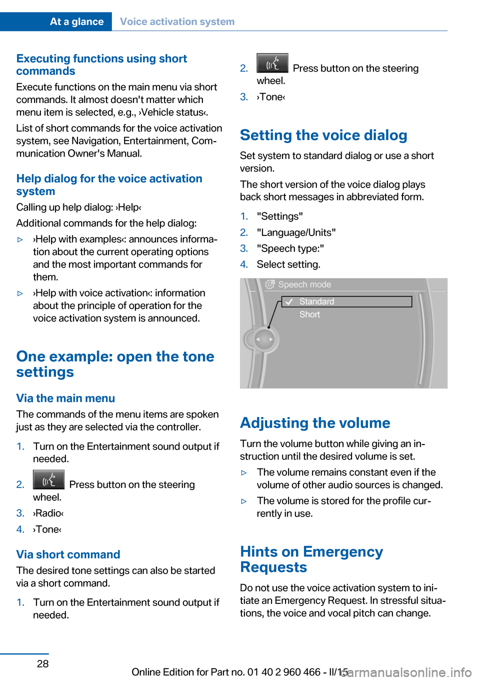
Setting the voice dialog
Set system to standard dialog or use a short
version.
The short version of the voice dialog plays
back short messages in abbreviated form.
1."Settings"2."Language/Units"3."Speech type:"4.Select setting.
Adjusting the volume
Turn the volume button while giving an in‐
struction until the desired volume is set.
▷The volume remains constant even if the
volume of other audio sources is changed.▷The volume is stored for the profile cur‐
rently in use.
Hints on Emergency
Requests
Do not use the voice activation system to ini‐
tiate an Emergency Request. In stressful situa‐
tions, the voice and vocal pitch can change.
Seite 28At a glanceVoice activation system28
Online Edition for Part no. 01 40 2 960 466 - II/15
Page 44 of 251
stored, if the vehicle has been used in the
meantime by a person with a different remote
control.
Changes to the settings are automatically
saved in the personal profile.
Three personal profiles and a guest profile can
be created.
Adjusting
The settings for the following systems and
functions are saved in the active profile. The
scope of storable settings is country- and
equipment-dependable.▷Unlocking and locking.▷Lights.▷Climate control.▷Radio.▷Instrument cluster.▷Programmable memory buttons.▷Volumes, tone.▷Control Display.▷Navigation.▷Park Distance Control PDC.▷Rearview camera▷Side View.▷Head-up Display.▷Driving Dynamics Control.▷Driver's seat position, exterior mirror posi‐
tion, steering wheel position.▷Cruise control.▷Intelligent Safety.▷Active Blind Spot Detection.
Profile management
Opening profiles Regardless of the remote control in use a dif‐
ferent profile may be activated.
1."Settings"2."Profiles"3.Select a profile.▷All settings stored in the called-up profile
are automatically applied.▷The called-up profile is assigned to the re‐
mote control being used at the time.▷If the profile is already assigned to a differ‐
ent remote control, this profile will apply to
both remote controls. It cannot be differen‐
tiated anymore between the settings for
the two remote controls.
Renaming profiles
A personal name can be assigned to every pro‐
file to avoid confusion between the profiles.
1."Settings"2."Profiles"3."Options"4."Rename current profile"
Resetting profiles
The settings of the active profile are reset to
their default values.
1."Settings"2."Profiles"3."Options"4."Reset current profile"
Exporting profiles
Most settings of the active profile can be ex‐
ported.
This can be helpful for securing and retrieving
personal settings, before delivering the vehicle
to a workshop, e.g. Profiles can be taken to an‐
other vehicle equipped with the Personal Pro‐
file function.
The following export options are available:
▷Via BMW Online.▷Via the USB port to a USB device.Seite 40ControlsOpening and closing40
Online Edition for Part no. 01 40 2 960 466 - II/15
Page 52 of 251
▷"Tailgate + door(s)"
The trunk lid is opened and the doors
are unlocked.
Confirmation signals from the vehicle
The settings are saved in the active profile, re‐
fer to page 39.
1."Settings"2."Doors/key"3.Deactivate or activate the desired confir‐
mation signals.▷"Acoustic sig. lock/unlock"▷"Flash when lock/unlock"
Automatic locking
The settings are saved in the active profile, re‐fer to page 39.
1."Settings"2."Doors/key"3.Select the desired function:▷"Lock if no door is opened"
The vehicle locks automatically after a
short period of time if no door is
opened.▷"Lock after start driving"
The vehicle locks automatically after
you drive off.
Headlamp courtesy delay feature/ standing climate control
The settings are saved in the active profile, re‐fer to page 39.
1."Settings"2."Doors/key"3. Select the symbol.4.Select the desired function:▷"Pathway lighting"
Headlight courtesy delay feature▷"Comfort cooling"Stationary climate control
Retrieving the seat and mirror settings The driver's seat and exterior mirror positions
used last are stored for the remote control cur‐
rently in use.
When the vehicle is unlocked, these positions
are automatically retrieved if this function was
activated.
Pinch hazard when moving back the seat
If this function is used, first make sure
that the footwell behind the driver's seat is
empty. Otherwise, people might get injured or
objects damaged when the seat is moved
back.◀
The adjustment procedure is interrupted:
▷When a seat position switch is pressed.▷When a button of the seat and mirror mem‐
ory is pressed.
Activating the setting
1."Settings"2."Doors/key"3."Last seat position autom."
Alarm system
The conceptWhen the vehicle is locked, the vehicle alarm
system responds to:
▷Opening a door, the hood or the trunk lid.▷Movements in the interior.▷Changes in the vehicle tilt, e. g., during at‐
tempts at stealing a wheel or when towing
the car.▷Disconnected battery voltage.
The alarm system briefly signals tampering:
▷By sounding an acoustic alarm.▷By switching on the hazard warning sys‐
tem.Seite 48ControlsOpening and closing48
Online Edition for Part no. 01 40 2 960 466 - II/15
Page 79 of 251
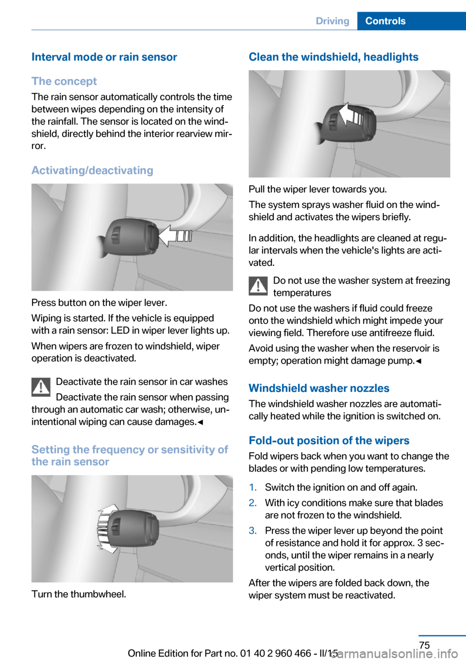
Interval mode or rain sensor
The concept The rain sensor automatically controls the time
between wipes depending on the intensity of the rainfall. The sensor is located on the wind‐
shield, directly behind the interior rearview mir‐
ror.
Activating/deactivating
Press button on the wiper lever.
Wiping is started. If the vehicle is equipped
with a rain sensor: LED in wiper lever lights up.
When wipers are frozen to windshield, wiper
operation is deactivated.
Deactivate the rain sensor in car washes
Deactivate the rain sensor when passing
through an automatic car wash; otherwise, un‐
intentional wiping can cause damages.◀
Setting the frequency or sensitivity of
the rain sensor
Turn the thumbwheel.
Clean the windshield, headlights
Pull the wiper lever towards you.
The system sprays washer fluid on the wind‐
shield and activates the wipers briefly.
In addition, the headlights are cleaned at regu‐
lar intervals when the vehicle's lights are acti‐
vated.
Do not use the washer system at freezing
temperatures
Do not use the washers if fluid could freeze
onto the windshield which might impede your
viewing field. Therefore use antifreeze fluid.
Avoid using the washer when the reservoir is
empty; operation might damage pump.◀
Windshield washer nozzles The windshield washer nozzles are automati‐
cally heated while the ignition is switched on.
Fold-out position of the wipers Fold wipers back when you want to change the
blades or with pending low temperatures.
1.Switch the ignition on and off again.2.With icy conditions make sure that blades
are not frozen to the windshield.3.Press the wiper lever up beyond the point
of resistance and hold it for approx. 3 sec‐
onds, until the wiper remains in a nearly
vertical position.
After the wipers are folded back down, the
wiper system must be reactivated.
Seite 75DrivingControls75
Online Edition for Part no. 01 40 2 960 466 - II/15
Page 82 of 251
Sport program and manual mode
Activating the sport program
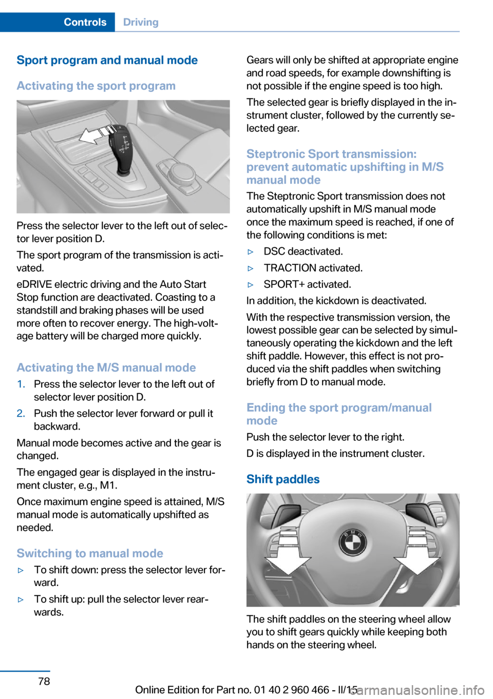
Press the selector lever to the left out of selec‐
tor lever position D.
The sport program of the transmission is acti‐
vated.
eDRIVE electric driving and the Auto Start
Stop function are deactivated. Coasting to a
standstill and braking phases will be used
more often to recover energy. The high-volt‐
age battery will be charged more quickly.
Activating the M/S manual mode
1.Press the selector lever to the left out of
selector lever position D.2.Push the selector lever forward or pull it
backward.
Manual mode becomes active and the gear is
changed.
The engaged gear is displayed in the instru‐
ment cluster, e.g., M1.
Once maximum engine speed is attained, M/S
manual mode is automatically upshifted as
needed.
Switching to manual mode
▷To shift down: press the selector lever for‐
ward.▷To shift up: pull the selector lever rear‐
wards.Gears will only be shifted at appropriate engine
and road speeds, for example downshifting is
not possible if the engine speed is too high.
The selected gear is briefly displayed in the in‐
strument cluster, followed by the currently se‐
lected gear.
Steptronic Sport transmission:
prevent automatic upshifting in M/S
manual mode
The Steptronic Sport transmission does not
automatically upshift in M/S manual mode
once the maximum speed is reached, if one of
the following conditions is met:▷DSC deactivated.▷TRACTION activated.▷SPORT+ activated.
In addition, the kickdown is deactivated.
With the respective transmission version, the
lowest possible gear can be selected by simul‐
taneously operating the kickdown and the left
shift paddle. However, this effect is not pro‐
duced via the shift paddles when switching
briefly from D to manual mode.
Ending the sport program/manual
mode
Push the selector lever to the right.
D is displayed in the instrument cluster.
Shift paddles
The shift paddles on the steering wheel allow
you to shift gears quickly while keeping both
hands on the steering wheel.
Seite 78ControlsDriving78
Online Edition for Part no. 01 40 2 960 466 - II/15
Page 110 of 251
size is detected on the seat. The airbags
on the front passenger side are activated.
Detected child seats
The system generally detects children seated
in a child seat, particularly in child seats re‐
quired by NHTSA when the vehicle was manu‐ factured. After installing a child seat, make
sure that the indicator lamp for the front-seat
passenger airbags lights up. This indicates
that the child seat has been detected and the
front-seat passenger airbags are not activated.
Strength of the driver's and front-seat
passenger airbag
The explosive power that activates driver's/
front passenger's airbags very much depends
on the positions of the driver's/front passeng‐ er's seat.
With a respective message appearing on Con‐
trol Display calibrate the front seats to keep the accuracy of this function over the long-
term.
Calibrating the front seats
A corresponding message appears on the
Control Display.
1.Press the reel and move the respective
seat all the way forward.2.Press the reel forward again. The seat still
moves forward slightly.3.Readjust the seat to the desired position.
The calibration procedure is completed when
the message on the Control Display disap‐
pears.
If the message continues to be displayed, re‐
peat the calibration.
If the message does not disappear after a re‐
peat calibration, have the system checked as
soon as possible.
Unobstructed area of movement
Ensure that the area of movement of the
seats is unobstructed to avoid personal injury
or damage to objects.◀
Tire Pressure Monitor TPM The concept
The system monitors tire inflation pressure in
the four mounted tires. The system warns you
if there is a significant loss of pressure in one
or more tires. For this purpose, sensors in the
tire valves measure the tire inflation pressure
and tire temperature.
Hints Tire damage due to external factors
Sudden tire damage caused by external
circumstances cannot be recognized in ad‐
vance.◀
With use of the system observe further infor‐
mation found under Tire inflation pressure, re‐
fer to page 192.
Functional requirements
The system must have been reset with the
correct tire inflation pressure; otherwise, relia‐
ble signaling of tire inflation pressure loss is
not assured.
Reset the system after each adjustment of the
tire inflation pressure and after every tire or
wheel change.
Always use wheels with TPM electronics to
ensure that the system will operate properly.
Status display
The current status of the Tire Pressure Moni‐
tor TPM can be displayed on the Control Dis‐
play, e.g., whether or not the TPM is active.
On the Control Display:1."Vehicle info"Seite 106ControlsSafety106
Online Edition for Part no. 01 40 2 960 466 - II/15
Page 111 of 251
2."Vehicle status"3. "Tire Pressure Monitor (TPM)"
The status is displayed.
Status control display Tire and system status are indicated by the
color of the wheels and a text message on the
Control Display.
All wheels green System is active and will issue a warning rela‐
tive to the tire inflation pressures stored during
the last reset.
One wheel is yellow A flat tire or major drop in inflation pressure in
the indicated tire.
All wheels are yellow A flat tire or major drop in inflation pressure in
several tires.
Wheels, gray The system cannot detect a flat tire. Reasons
for this may be:
▷The system is being reset.▷Malfunction.
Status information
The status control display additionally shows
the current tire inflation pressures and, de‐
pending on the model, tire temperatures. It
shows the actual values read; they may vary depending on driving style or weather condi‐
tions.
Carry out reset Reset the system after each adjustment of the
tire inflation pressure and after every tire or
wheel change.
On the Control Display and on the vehicle:1."Vehicle info"2."Vehicle status"3. "Perform reset"4.Start the engine - do not drive off.5.Reset tire inflation pressure:"Perform
reset".6.Drive away.
The tires are shown in gray and the status is
displayed.
After driving faster than 19 mph/30 km/h for a
short period, the set tire inflation pressures are
accepted as reference values. The reset is
completed automatically while driving.
After a successfully completed Reset, the
wheels on the Control Display are shown in
green and "Tire Pressure Monitor (TPM)
active" is displayed.
You may interrupt this trip at any time. When
you continue the reset resumes automatically.
Low tire pressure message The yellow warning lamp lights up. A
Check Control message is displayed.
▷There is a flat tire or a major loss in
tire inflation pressure.▷No reset was performed for the system.
The system therefore issues a warning
based on the tire inflation pressures before
the last reset.1.Reduce your speed and stop cautiously.
Avoid sudden braking and steering maneu‐
vers.2.Check whether the vehicle is fitted with
regular tires or run-flat tires.
Run-flat tires, refer to page 198, are la‐
beled with a circular symbol containing the
letters RSC marked on the tire's sidewall.Seite 107SafetyControls107
Online Edition for Part no. 01 40 2 960 466 - II/15
Page 112 of 251
Do not continue driving without run-flat
tires
Do not continue driving if the vehicle is not
equipped with run-flat tires; continued driving
may result in serious accidents.◀
A low tire inflation pressure might turn on DSC
Dynamic Stability Control.
Actions in the event of a flat tireNormal tires1.Identify the damaged tire.
Do this by checking the air pressure in all
four tires.
The tire pressure gage of the Mobility Sys‐
tem, refer to page 198, can possibly be
used for this purpose.
If the tire inflation pressure in all four tires
is shown to be correct, it is possible that
the Tire Pressure Monitor did not perform
a reset. Then perform the reset.
If an identification is not possible, please
contact the service center.2.Fixing a flat tire, where applicable with the
Mobility System.
Use of tire sealant, e.g., the Mobility System,
may damage the TPM wheel electronics. In
this case, have the electronics checked at the
next opportunity and have them replaced if
needed.
Run-flat tires
Maximum speed
You may continue driving with a damaged tire
at speeds up to 50 mph/80 km/h.
Continued driving with a flat tire
If continuing to drive with a damaged tire:
1.Avoid sudden braking and steering maneu‐
vers.2.Do not exceed a speed of 50 mph/80 km/h.3.Check the air pressure in all four tires at
the next opportunity.
If the tire inflation pressure in all four tires
is shown to be correct, it is possible that
the Tire Pressure Monitor did not perform
a reset. In that case, carry out a reset.
Possible driving distance with complete loss of
tire inflation pressure:
The possible driving distance after a loss of tire
inflation pressure depends on cargo load, driv‐
ing style and road conditions.
A vehicle with an average load has a possible
driving range of approx. 50 miles/80 km.
A vehicle with a damaged tire reacts differ‐
ently, e.g., it has reduced lane stability during
braking, a longer braking distance and different
self-steering properties. Adjust your driving
style accordingly. Avoid abrupt steering ma‐
neuvers or driving over obstacles, e.g., curbs,
potholes, etc.
Because the possible driving distance de‐
pends on how the vehicle is used during the
trip, the actual distance may be shorter or lon‐
ger depending on the driving speed, road con‐
ditions, external temperature, cargo load, etc.
Continued driving with a flat tire
Drive moderately and do not exceed a
speed of 50 mph/80 km/h.
Your car handles differently when you lose tire
inflation pressure, e.g., your lane stability is re‐
duced when braking, braking distances are
longer and the self-steering properties will
change.◀
Final tire failure
Vibrations or loud noises while driving
can indicate the final failure of a tire. Reduce
speed and stop; otherwise, pieces of the tire
could come loose and cause an accident. Do
not continue driving and contact your service
center.◀
Seite 108ControlsSafety108
Online Edition for Part no. 01 40 2 960 466 - II/15
Page 113 of 251
Required tire inflation pressure check
message
A Check Control message is displayed in the
following situations▷The system has detected a wheel change,
but no reset was done.▷Inflation was not carried out according to
specifications.▷The tire inflation pressure has fallen below
the level of the last confirmation.
In this case:
▷Check the tire pressure and correct as
needed.▷Carry out a reset of the system after a tire
change.
System limits
The system does not function properly if a re‐
set has not been carried out, e.g., a flat tire is
reported though tire inflation pressures are
correct.
The tire inflation pressure depends on the
tire's temperature. Driving or exposure to the
sun will increase the tire's temperature, thus
increasing the tire inflation pressure. The tire
inflation pressure is reduced when the tire
temperature falls again. These circumstances
may cause a warning when temperatures fall
very sharply.
Malfunction The yellow warning lamp flashes and
then lights up continuously. A Check
Control message is displayed. No flat
tire or loss of tire inflation pressure can be de‐
tected.
Display in the following situations:
▷A wheel without TPM electronics is fitted:
have the service center check it if needed.▷Malfunction: have the system checked by
your service center.▷TPM was unable to complete the reset.
Reset the system again.▷Interference through systems or devices
with the same radio frequency: after leav‐
ing the area of the interference, the system
automatically becomes active again.
Declaration according to NHTSA/
FMVSS 138 Tire Pressure Monitoring
System
Each tire, including the spare (if provided)
should be checked monthly when cold and in‐
flated to the inflation pressure recommended
by the vehicle manufacturer on the vehicle
placard or tire inflation pressure label. (If your
vehicle has tires of a different size than the size
indicated on the vehicle placard or tire inflation
pressure label, you should determine the
proper tire inflation pressure for those tires.)
As an added safety feature, your vehicle has
been equipped with a tire pressure monitoring
system (TPMS) that illuminates a low tire pres‐
sure telltale when one or more of your tires is
significantly under-inflated. Accordingly, when
the low tire pressure telltale illuminates, you
should stop and check your tires as soon as
possible, and inflate them to the proper pres‐
sure. Driving on a significantly under-inflated
tire causes the tire to overheat and can lead to
tire failure. Under-inflation also reduces fuel ef‐
ficiency and tire tread life, and may affect the
vehicle's handling and stopping ability. Please
note that the TPMS is not a substitute for
proper tire maintenance, and it is the driver's
responsibility to maintain correct tire pressure,
even if under-inflation has not reached the
level to trigger illumination of the TPMS low
tire pressure telltale. Your vehicle has also
been equipped with a TPMS malfunction indi‐
cator to indicate when the system is not oper‐
ating properly. The TPMS malfunction indica‐
tor is combined with the low tire pressure
telltale. When the system detects a malfunc‐
tion, the telltale will flash for approximately one
minute and then remain continuously illumi‐
nated. This sequence will continue upon sub‐
Seite 109SafetyControls109
Online Edition for Part no. 01 40 2 960 466 - II/15