stop start BMW ACTIVE HYBRID 7 2013 F04 User Guide
[x] Cancel search | Manufacturer: BMW, Model Year: 2013, Model line: ACTIVE HYBRID 7, Model: BMW ACTIVE HYBRID 7 2013 F04Pages: 253, PDF Size: 5.01 MB
Page 87 of 253
Sport program and manual mode
Activating the sport program
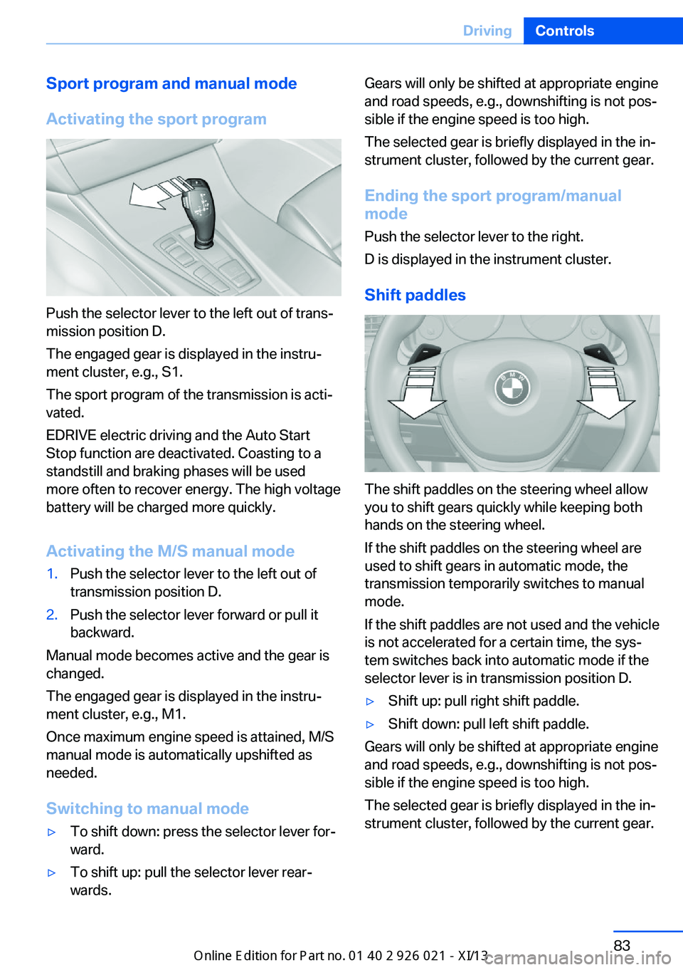
Push the selector lever to the left out of trans‐
mission position D.
The engaged gear is displayed in the instru‐
ment cluster, e.g., S1.
The sport program of the transmission is acti‐
vated.
EDRIVE electric driving and the Auto Start
Stop function are deactivated. Coasting to a
standstill and braking phases will be used
more often to recover energy. The high voltage
battery will be charged more quickly.
Activating the M/S manual mode
1.Push the selector lever to the left out of
transmission position D.2.Push the selector lever forward or pull it
backward.
Manual mode becomes active and the gear is
changed.
The engaged gear is displayed in the instru‐
ment cluster, e.g., M1.
Once maximum engine speed is attained, M/S
manual mode is automatically upshifted as
needed.
Switching to manual mode
▷To shift down: press the selector lever for‐
ward.▷To shift up: pull the selector lever rear‐
wards.Gears will only be shifted at appropriate engine
and road speeds, e.g., downshifting is not pos‐
sible if the engine speed is too high.
The selected gear is briefly displayed in the in‐
strument cluster, followed by the current gear.
Ending the sport program/manual
mode
Push the selector lever to the right.
D is displayed in the instrument cluster.
Shift paddles
The shift paddles on the steering wheel allow
you to shift gears quickly while keeping both
hands on the steering wheel.
If the shift paddles on the steering wheel are
used to shift gears in automatic mode, the
transmission temporarily switches to manual
mode.
If the shift paddles are not used and the vehicle
is not accelerated for a certain time, the sys‐
tem switches back into automatic mode if the
selector lever is in transmission position D.
▷Shift up: pull right shift paddle.▷Shift down: pull left shift paddle.
Gears will only be shifted at appropriate engine
and road speeds, e.g., downshifting is not pos‐
sible if the engine speed is too high.
The selected gear is briefly displayed in the in‐
strument cluster, followed by the current gear.
Seite 83DrivingControls83
Online Edition for Part no. 01 40 2 909 774 - VI/13
Page 98 of 253
Information at a glanceRepeatedly pressing the button on the turn
signal lever calls up the following information
on the info display:▷Range.▷Average fuel consumption.▷Average speed.▷Date.▷Speed limit detection.▷Time of arrival.
When destination guidance is activated in
the navigation system.▷Distance to destination.
When destination guidance is activated in
the navigation system.▷Arrow view of navigation system.
When destination guidance is activated in
the navigation system.
When the arrow view in the Head-up Dis‐
play is inactive.▷ECO PRO bonus range.▷Charge state of the high-voltage battery as
a percentage.
Adjusting the info display
You can select what information from the on‐
board computer is to be displayed on the info
display of the instrument cluster.
1."Settings"2."Info display"3.Select the desired displays.
Information in detail
Range
Displays the estimated cruising range available
with the remaining fuel.
It is calculated based on your driving style over
the last 20 miles/30 km. If there is only enough
fuel left for less than 45 miles/80 km, the color
of the display changes.
Average fuel consumption
The average fuel consumption is calculated for
the period during which the engine is running.
The average fuel consumption is calculated for
the distance traveled since the last reset by the
onboard computer.
Average speed
Periods in which the vehicle is parked with the
engine manually stopped do not enter into the
calculation of the average speed.
Resetting average values
Press and hold the computer button on the
turn signal lever.
Distance to destination
The distance remaining to the destination is
displayed if a destination is entered in the navi‐
gation system before the trip is started.
The distance to the destination is adopted au‐
tomatically.
Time of arrival The estimated time of arrival is
displayed if a destination is en‐
tered in the navigation system
before the trip is started.
The time must be correctly set.
Speed limit detection Description of the speed limit detection, refer
to page 91, function.
Speed limit Display of a speed limit which, when reached,
should cause a warning to be issued.
The warning is repeated if the vehicle speed
drops below the set speed limit once by at
least 3 mph/5 km/h.Seite 94ControlsDisplays94
Online Edition for Part no. 01 40 2 909 774 - VI/13
Page 101 of 253
▷Electric driving: eDRIVE.▷Acceleration boost: eBOOST.▷Energy recovery: CHARGE.▷Auto Start/Stop function: READY.
The display depends on the system's operat‐
ing condition.
Note High voltage
Even if no bars are displayed in the bat‐
tery symbol, the hybrid system is still under high voltage.◀
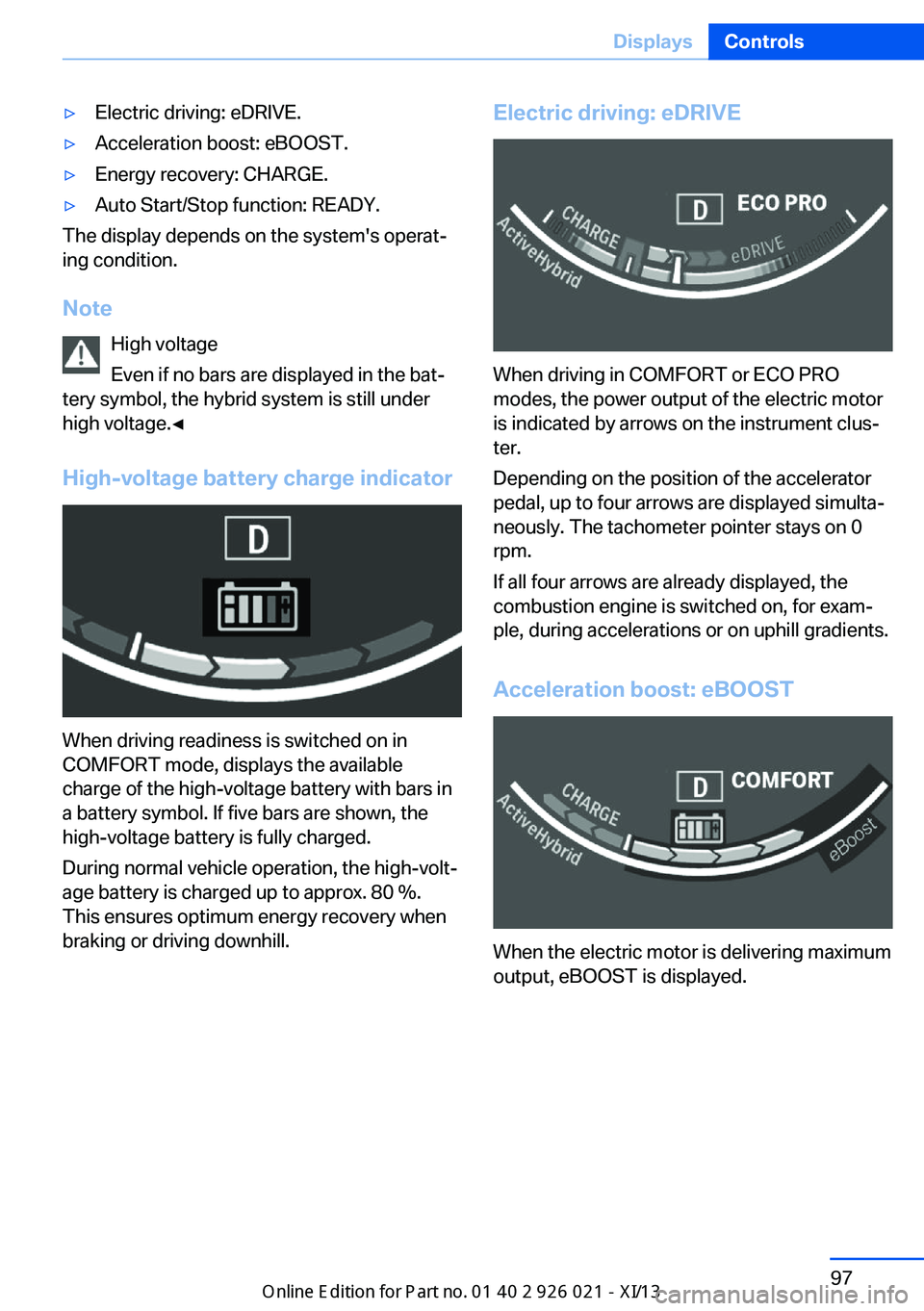
High-voltage battery charge indicator
When driving readiness is switched on in
COMFORT mode, displays the available
charge of the high-voltage battery with bars in
a battery symbol. If five bars are shown, the
high-voltage battery is fully charged.
During normal vehicle operation, the high-volt‐
age battery is charged up to approx. 80 %.
This ensures optimum energy recovery when
braking or driving downhill.
Electric driving: eDRIVE
When driving in COMFORT or ECO PRO
modes, the power output of the electric motor
is indicated by arrows on the instrument clus‐
ter.
Depending on the position of the accelerator
pedal, up to four arrows are displayed simulta‐
neously. The tachometer pointer stays on 0
rpm.
If all four arrows are already displayed, the
combustion engine is switched on, for exam‐
ple, during accelerations or on uphill gradients.
Acceleration boost: eBOOST
When the electric motor is delivering maximum
output, eBOOST is displayed.
Seite 97DisplaysControls97
Online Edition for Part no. 01 40 2 909 774 - VI/13
Page 102 of 253
Energy recovery: CHARGE
The energy recovered is indicated in the in‐
strument cluster: in COMFORT mode by ar‐
rows and in ECO PRO mode by a bar below
the CHARGE display. The high voltage battery
is being charged.
Auto Start/Stop function: READY READY indicates drive readi‐
ness.
Indications on the Control Display Displaying the hybrid system
utilization
1."Vehicle Info"2."Hybrid"3. "Hybrid usage"
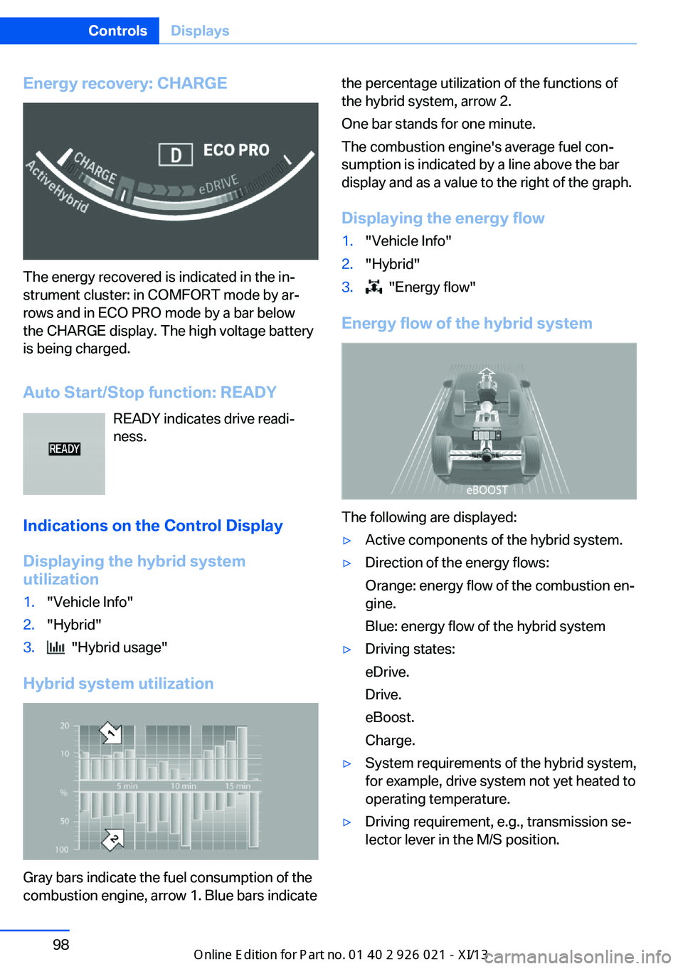
Hybrid system utilization
Gray bars indicate the fuel consumption of the
combustion engine, arrow 1. Blue bars indicate
the percentage utilization of the functions of
the hybrid system, arrow 2.
One bar stands for one minute.
The combustion engine's average fuel con‐
sumption is indicated by a line above the bar
display and as a value to the right of the graph.
Displaying the energy flow1."Vehicle Info"2."Hybrid"3. "Energy flow"
Energy flow of the hybrid system
The following are displayed:
▷Active components of the hybrid system.▷Direction of the energy flows:
Orange: energy flow of the combustion en‐
gine.
Blue: energy flow of the hybrid system▷Driving states:
eDrive.
Drive.
eBoost.
Charge.▷System requirements of the hybrid system,
for example, drive system not yet heated to
operating temperature.▷Driving requirement, e.g., transmission se‐
lector lever in the M/S position.Seite 98ControlsDisplays98
Online Edition for Part no. 01 40 2 909 774 - VI/13
Page 113 of 253
5.Start the initialization with "Perform reset".6.Drive away.
The initialization is completed while driving,
which can be interrupted at any time.
The initialization automatically continues when
driving resumes.
Indication of a flat tire The yellow warning lamp lights up. A
Check Control message is displayed.
There is a flat tire or a major loss in tire
inflation pressure.
1.Reduce your speed and stop cautiously.
Avoid sudden braking and steering maneu‐
vers.2.Check whether the vehicle is fitted with
regular tires or run-flat tires.
Run-flat tires, refer to page 205, are la‐
beled with a circular symbol containing the
letters RSC marked on the tire sidewall.
Do not continue driving without run-flat
tires
Do not continue driving if the vehicle is not
equipped with run-flat tires; continued driving
may result in serious accidents.◀
When a flat tire is indicated, DSC Dynamic Sta‐
bility Control is switched on if necessary.
System limits Sudden tire damage
Sudden serious tire damage caused by
external influences cannot be indicated in ad‐
vance.◀
A natural, even pressure loss in all four tires
cannot be detected. Therefore, check the tire
inflation pressure regularly.
The system could be delayed or malfunction in
the following situations:
▷When the system has not been initialized.▷When driving on a snowy or slippery road
surface.▷Sporty driving style: slip in the drive
wheels, high lateral acceleration.▷When driving with snow chains.
Actions in the event of a flat tire
Normal tires
1.Identify the damaged tire.
Do this by checking the air pressure in all
four tires.
If the tire inflation pressure in all four tires
is correct, the Flat Tire Monitor may not
have been initialized. In this case, initialize
the system.
If an identification is not possible, please
contact the service center.2.Rectify the flat tire.
Run-flat tires
Maximum speed
You can continue driving with a damaged tire
at speeds up to 50 mph/80 km/h.
Continued driving with a flat tire
If continuing to drive with a damaged tire:
1.Avoid sudden braking and steering maneu‐
vers.2.Do not exceed a speed of 50 mph/80 km/h.3.Check the air pressure in all four tires at
the next opportunity.
If the tire inflation pressure in all four tires
is correct, the Flat Tire Monitor may not
have been initialized. In this case, initialize
the system.
Possible driving distance with complete loss of
tire inflation pressure:
The possible driving distance after a loss of tire
inflation pressure depends on the cargo load
and the driving style and conditions.
Seite 109SafetyControls109
Online Edition for Part no. 01 40 2 909 774 - VI/13
Page 115 of 253
All wheels are yellowA flat tire or major drop in inflation pressure in
several tires.
Wheels, gray The system cannot detect a flat tire. Reasons
for this may be:▷The system is being reset.▷Malfunction.
Additional information
The status display additionally shows the cur‐
rent tire inflation pressures and tire tempera‐
tures. The values shown are current measure‐
ment values and may vary depending on
driving style or weather conditions.
Carry out reset Reset the system after each correction of the
tire inflation pressure and after every tire or
wheel change.
1."Vehicle Info"2."Vehicle status"3. "Perform reset"4.Start the engine - do not drive away.5.Carry out the reset with "Perform reset".6.Drive away.
The tires are shown in gray and the status is
displayed.
After driving faster than 19 mph/30 km/h for a
short period, the tire inflation pressures set are
accepted as reference values. The reset is
completed automatically during driving.
After a successfully completed Reset, the
wheels on the Control Display are shown in
green and "Tire Pressure Monitor (TPM)
active" is displayed.
The trip can be interrupted at any time. If you
drive away again, the reset resumes automati‐
cally.
Low tire pressure message
The yellow warning lamp lights up. A
Check Control message is displayed.▷There is a flat tire or a major loss in
tire inflation pressure.▷No reset was performed for the system.
The system therefore issues a warning
based on the tire pressures before the last
reset.1.Reduce your speed and stop cautiously.
Avoid sudden braking and steering maneu‐
vers.2.Check whether the vehicle is fitted with
regular tires or run-flat tires.
Run-flat tires, refer to page 205, are la‐
beled with a circular symbol containing the
letters RSC marked on the tire sidewall.
Do not continue driving without run-flat
tires
Do not continue driving if the vehicle is not
equipped with run-flat tires; continued driving
may result in serious accidents.◀
When a low inflation pressure is indicated,
DSC Dynamic Stability Control is switched on
if necessary.
Actions in the event of a flat tire
Normal tires
1.Identify the damaged tire.
Do this by checking the air pressure in all
four tires.
If the tire inflation pressure in all four tires
is correct, it is possible that a reset was not
carried out for the Tire Pressure Monitor. In
that case, carry out a reset.
If an identification is not possible, please
contact the service center.2.Rectify the flat tire.
Use of tire sealant, e.g., the Mobility Sys‐
tem, may damage the TPM wheel elec‐Seite 111SafetyControls111
Online Edition for Part no. 01 40 2 909 774 - VI/13
Page 117 of 253
Control message is displayed. No flat tire or
loss of tire pressure can be detected.
Display in the following situations:▷A wheel without TPM electronics is fitted:
have the service center check it if neces‐
sary.▷Malfunction: have the system checked by
your service center.▷TPM was unable to complete the reset.
Reset the system again.▷Disturbance by systems or devices with
the same radio frequency: after leaving the
area of the disturbance, the system auto‐
matically becomes active again.
Declaration according to NHTSA/
FMVSS 138 Tire Pressure Monitoring
System
Each tire, including the spare (if provided)
should be checked monthly when cold and in‐
flated to the inflation pressure recommended
by the vehicle manufacturer on the vehicle
placard or tire inflation pressure label. (If your
vehicle has tires of a different size than the size
indicated on the vehicle placard or tire inflation
pressure label, you should determine the
proper tire inflation pressure for those tires.)
As an added safety feature, your vehicle has
been equipped with a tire pressure monitoring
system (TPMS) that illuminates a low tire pres‐
sure telltale when one or more of your tires is
significantly under-inflated. Accordingly, when
the low tire pressure telltale illuminates, you
should stop and check your tires as soon as
possible, and inflate them to the proper pres‐
sure. Driving on a significantly under-inflated
tire causes the tire to overheat and can lead to
tire failure. Under-inflation also reduces fuel ef‐
ficiency and tire tread life, and may affect the
vehicle's handling and stopping ability. Please
note that the TPMS is not a substitute for
proper tire maintenance, and it is the driver's
responsibility to maintain correct tire pressure,
even if under-inflation has not reached the
level to trigger illumination of the TPMS low
tire pressure telltale. Your vehicle has also
been equipped with a TPMS malfunction indi‐
cator to indicate when the system is not oper‐
ating properly. The TPMS malfunction indica‐
tor is combined with the low tire pressure
telltale. When the system detects a malfunc‐
tion, the telltale will flash for approximately one
minute and then remain continuously illumi‐
nated. This sequence will continue upon sub‐
sequent vehicle start-ups as long as the mal‐
function exists. When the malfunction indicator
is illuminated, the system may not be able to
detect or signal low tire pressure as intended.
TPMS malfunctions may occur for a variety of
reasons, including the installation of replace‐
ment or alternate tires or wheels on the vehicle
that prevent the TPMS from functioning prop‐
erly. Always check the TPMS malfunction tell‐
tale after replacing one or more tires or wheels
on your vehicle to ensure that the replacement
or alternate tires and wheels allow the TPMS
to continue to function properly.
Intelligent Safety
The concept Depending on how the vehicle is equipped, In‐
telligent Safety consists of one or more of the
following systems, which can help to avoid an
imminent collision. These systems are active
automatically every time the engine is started
using the Start/Stop button:▷Collision warning, refer to page 114.▷Pedestrian warning, refer to page 118.
Note
Personal responsibility
The system does not serve as a substi‐
tute for the driver's personal judgment of the
traffic situation.
Seite 113SafetyControls113
Online Edition for Part no. 01 40 2 909 774 - VI/13
Page 118 of 253
Be aware of the traffic situation and the vehi‐
cle's surroundings at all times, otherwise an
accident is still possible despite all warnings.◀
At a glance
Button in the vehicle
Intelligent Safety button
Switching on/off The Intelligent Safety systems are automati‐
cally active after each engine start via the start/
stop button.
Press the button: the systems are
switched off. The LED goes out.
Press the button: the systems are switched off.
The LED lights up.
Settings can be made on the Control Display.
Collision warning
Depending on how the equipment is equipped,
the collision warning system consists of one of
the two systems:
▷Collision warning with City Braking func‐
tion, refer to page 114;Collision warning with City
Braking function
The concept The system can help to prevent accidents. If
an accident cannot be prevented, the system
helps to reduce the collision speed.
The system issues a warning if there is immi‐
nent danger of a collision and if so brakes inde‐
pendently.
The automatic braking intervention is done
with limited force and duration.
The system is controlled via a camera in the
base of the mirror.
The collision warning is available even if cruise
control has been deactivated.
When the vehicle is intentionally brought close
to a vehicle, the collision warning is delayed to
avoid false warnings.
General information
The system issues a two-phase warning of a
danger of collision with vehicles at speeds
above approx. 3 mph/5 km/h. The time of these
warnings may vary depending on the current
driving situation.
Up to approx. 35 mph/60 km/h a braking inter‐
vention occurs when appropriate.
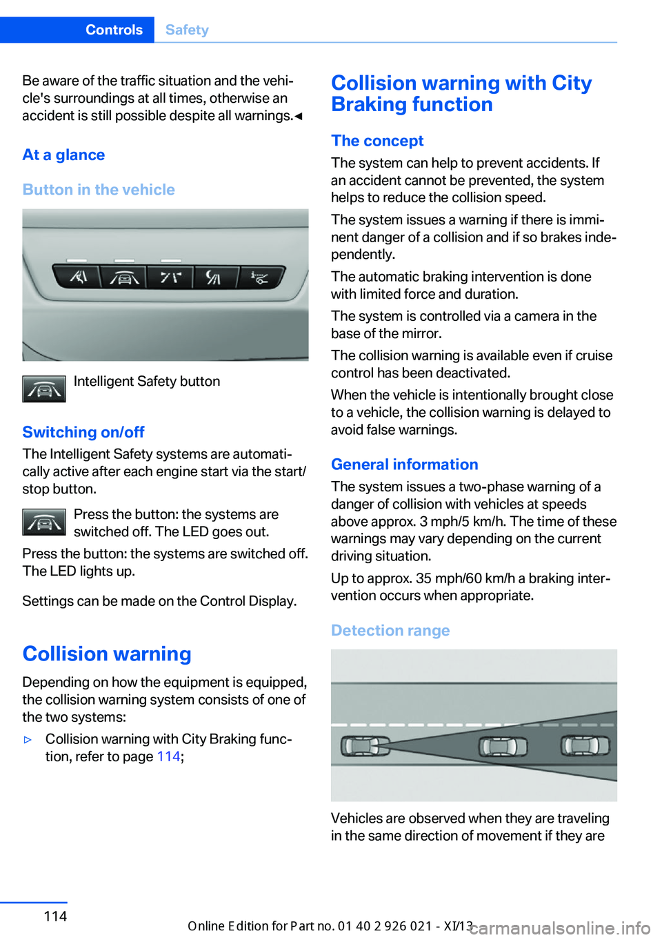
Detection range
Vehicles are observed when they are traveling
in the same direction of movement if they are
Seite 114ControlsSafety114
Online Edition for Part no. 01 40 2 909 774 - VI/13
Page 119 of 253
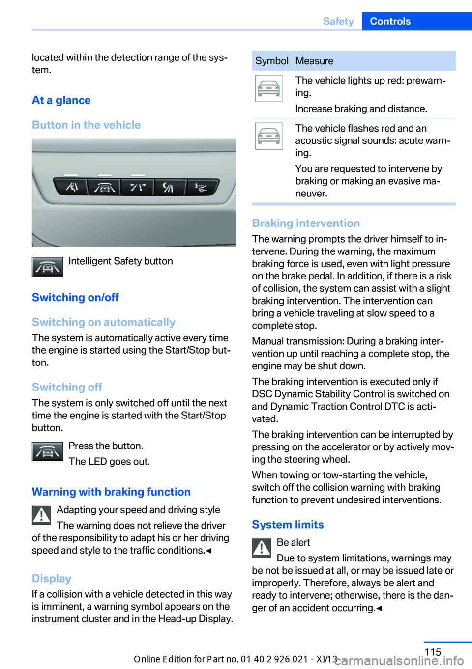
located within the detection range of the sys‐
tem.
At a glance
Button in the vehicle
Intelligent Safety button
Switching on/off
Switching on automatically The system is automatically active every time
the engine is started using the Start/Stop but‐
ton.
Switching off The system is only switched off until the next
time the engine is started with the Start/Stop
button.
Press the button.
The LED goes out.
Warning with braking function Adapting your speed and driving style
The warning does not relieve the driver
of the responsibility to adapt his or her driving
speed and style to the traffic conditions.◀
Display
If a collision with a vehicle detected in this way
is imminent, a warning symbol appears on the
instrument cluster and in the Head-up Display.
SymbolMeasureThe vehicle lights up red: prewarn‐
ing.
Increase braking and distance.The vehicle flashes red and an
acoustic signal sounds: acute warn‐
ing.
You are requested to intervene by
braking or making an evasive ma‐
neuver.
Braking intervention
The warning prompts the driver himself to in‐
tervene. During the warning, the maximum
braking force is used, even with light pressure
on the brake pedal. In addition, if there is a risk
of collision, the system can assist with a slight
braking intervention. The intervention can
bring a vehicle traveling at slow speed to a
complete stop.
Manual transmission: During a braking inter‐
vention up until reaching a complete stop, the
engine may be shut down.
The braking intervention is executed only if
DSC Dynamic Stability Control is switched on
and Dynamic Traction Control DTC is acti‐
vated.
The braking intervention can be interrupted by
pressing on the accelerator or by actively mov‐
ing the steering wheel.
When towing or tow-starting the vehicle,
switch off the collision warning with braking
function to prevent undesired interventions.
System limits Be alert
Due to system limitations, warnings may
be not be issued at all, or may be issued late or
improperly. Therefore, always be alert and ready to intervene; otherwise, there is the dan‐
ger of an accident occurring.◀
Seite 115SafetyControls115
Online Edition for Part no. 01 40 2 909 774 - VI/13
Page 121 of 253
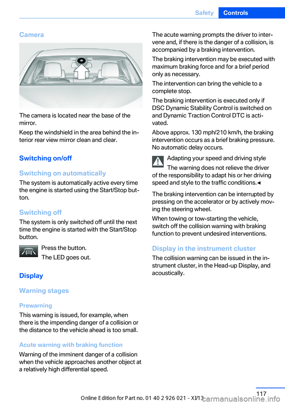
Camera
The camera is located near the base of the
mirror.
Keep the windshield in the area behind the in‐
terior rear view mirror clean and clear.
Switching on/off
Switching on automatically The system is automatically active every time
the engine is started using the Start/Stop but‐
ton.
Switching off The system is only switched off until the next
time the engine is started with the Start/Stop
button.
Press the button.
The LED goes out.
Display
Warning stages
Prewarning
This warning is issued, for example, when
there is the impending danger of a collision or
the distance to the vehicle ahead is too small.
Acute warning with braking function
Warning of the imminent danger of a collision
when the vehicle approaches another object at
a relatively high differential speed.
The acute warning prompts the driver to inter‐
vene and, if there is the danger of a collision, is
accompanied by a braking intervention.
The braking intervention may be executed with
maximum braking force and for a brief period
only as necessary.
The intervention can bring the vehicle to a
complete stop.
The braking intervention is executed only if
DSC Dynamic Stability Control is switched on
and Dynamic Traction Control DTC is acti‐
vated.
Above approx. 130 mph/210 km/h, the braking
intervention occurs as a brief braking pressure.
No automatic delay occurs.
Adapting your speed and driving style
The warning does not relieve the driver
of the responsibility to adapt his or her driving
speed and style to the traffic conditions.◀
The braking intervention can be interrupted by
pressing on the accelerator or by actively mov‐
ing the steering wheel.
When towing or tow-starting the vehicle,
switch off the collision warning with braking
function to prevent undesired interventions.
Display in the instrument cluster The collision warning can be issued in the in‐
strument cluster, in the Head-up Display, and
acoustically.Seite 117SafetyControls117
Online Edition for Part no. 01 40 2 909 774 - VI/13