warning light BMW I3 2015 I01 Owner's Guide
[x] Cancel search | Manufacturer: BMW, Model Year: 2015, Model line: I3, Model: BMW I3 2015 I01Pages: 236, PDF Size: 17.6 MB
Page 134 of 236
▷Each time the rocker switch is pressed
past the point of resistance, the desired
speed increases or decreases by a maxi‐
mum of 5 mph/10 km/h.
The maximum speed that can be set de‐
pends on the vehicle.▷Pressing the rocker switch to the resist‐
ance point and holding it accelerates or de‐
celerates the vehicle without requiring
pressure on the accelerator pedal.
After the rocker switch is released, the ve‐
hicle maintains its final speed. Pressing the
switch beyond the resistance point causes
the vehicle to accelerate more rapidly.
Resuming the desired speed
Press button.
The stored speed is reached and maintained. Displays in the instrument cluster
Indicator lamp Depending on how the vehicle is equip‐
ped, the indicator lamp in the instru‐
ment cluster indicates whether the sys‐
tem is switched on.
Desired speed The desired speed is displayed next to
the symbol in the info display.
▷The indicator lights up green: the
system is active.▷The indicator lights up orange: the system
has been interrupted.▷No display: system is switched off.
Status display
Selected desired speed.
If --- appears briefly on the display for Check
Control messages, it is possible that the sys‐
tem requirements are currently not ready for
operations.
PDC Park Distance Control The conceptPDC is a support when parking. When you
slowly approach an object in the rear - or also
in the front of the vehicle if the feature is availa‐
ble - then the object is reported through:▷Signal tones.▷Visual display.
General information
Ultrasound sensors in the bumpers measure
the distances from objects.
The maneuvering range, depending on the ob‐
stacle and environmental conditions, is approx.
6 ft/2 m.
An acoustic warning is first given:
▷By the front sensors and the two rear cor‐
ner sensors at approx. 24 in/60 cm.▷By the rear middle sensors at approx.
5 ft/1.50 m.
To ensure full functionality:
▷Do not cover sensors, e.g., with stickers,
bicycle racks.▷Keep the sensors clean and free of ice.▷When using high-pressure washers, do not
spray the sensors for long periods and
maintain a distance of at least 12 in/30 cm.
Hints
Personal responsibility
Even an active system does not relieve
the driver from personal responsibility while
driving.
Technically the system has its limits, it cannot
independently react to all traffic situations.
Seite 118ControlsDriving comfort118
Online Edition for Part no. 01 40 2 960 865 - II/15
Page 135 of 236
Monitor your driving, be on the alert, observe
the vehicle surroundings and other traffic and
react when needed - risk of accident.◀
Avoid driving fast with PDC
Avoid approaching an object too fast.
Avoid driving off fast while PDC is not yet ac‐
tive.
For technical reasons, the system may other‐
wise be too late in issuing a warning.◀
Overview
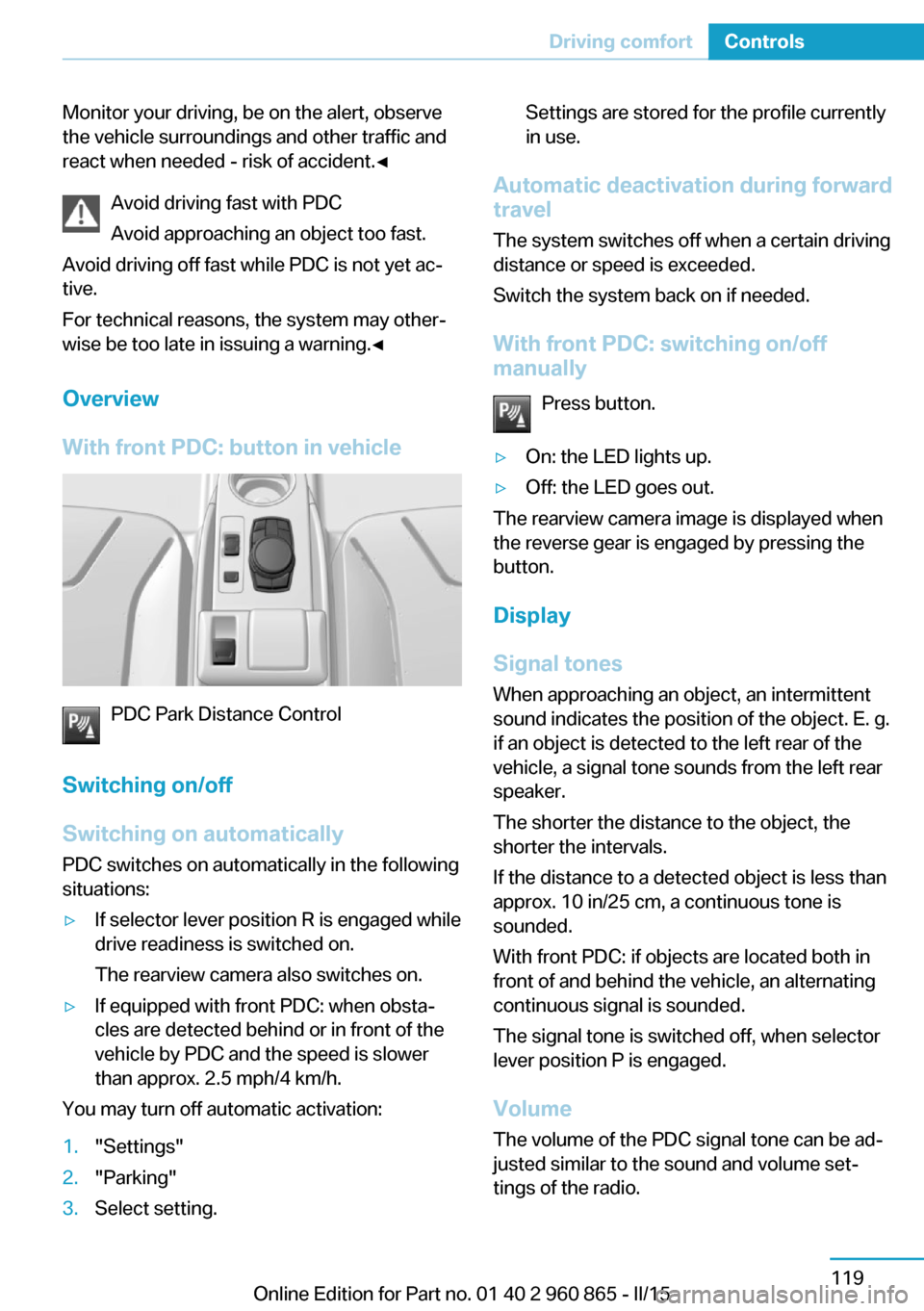
With front PDC: button in vehicle
PDC Park Distance Control
Switching on/off
Switching on automatically PDC switches on automatically in the following
situations:
▷If selector lever position R is engaged while
drive readiness is switched on.
The rearview camera also switches on.▷If equipped with front PDC: when obsta‐
cles are detected behind or in front of the
vehicle by PDC and the speed is slower
than approx. 2.5 mph/4 km/h.
You may turn off automatic activation:
1."Settings"2."Parking"3.Select setting.Settings are stored for the profile currently
in use.
Automatic deactivation during forward
travel
The system switches off when a certain driving
distance or speed is exceeded.
Switch the system back on if needed.
With front PDC: switching on/off
manually
Press button.
▷On: the LED lights up.▷Off: the LED goes out.
The rearview camera image is displayed when
the reverse gear is engaged by pressing the
button.
Display
Signal tones When approaching an object, an intermittent
sound indicates the position of the object. E. g.
if an object is detected to the left rear of the
vehicle, a signal tone sounds from the left rear
speaker.
The shorter the distance to the object, the
shorter the intervals.
If the distance to a detected object is less than
approx. 10 in/25 cm, a continuous tone is
sounded.
With front PDC: if objects are located both in
front of and behind the vehicle, an alternating
continuous signal is sounded.
The signal tone is switched off, when selector
lever position P is engaged.
Volume
The volume of the PDC signal tone can be ad‐
justed similar to the sound and volume set‐
tings of the radio.
Seite 119Driving comfortControls119
Online Edition for Part no. 01 40 2 960 865 - II/15
Page 136 of 236
Settings are stored for the profile currently in
use.
Visual warning
The approach of the vehicle to an object can
be shown on the Control Display. Objects that
are farther away are already displayed on the
Control Display before a signal sounds.
A display appears as soon as Park Distance
Control (PDC) is activated.
The range of the sensors is represented in the
colors green, yellow and red.
When the image of the rearview camera is dis‐
played, the reel can be made to PDC:
"Rear view camera"
System limits
Limits of ultrasonic measurement
Ultrasonic measuring might not function under
the following circumstances:
▷For small children and animals.▷For persons with certain clothing, e.g.
coats.▷With external interference of the ultra‐
sound, e.g. from passing vehicles or loud
machines.▷When sensors are dirty, iced over, dam‐
aged or out of position.▷Under certain weather conditions such as
high relative humidity, rain, snowfall, ex‐
treme heat or strong wind.▷With tow bars and trailer couplings of other
vehicles.▷With thin or wedge-shaped objects.▷With moving objects.▷With elevated, protruding objects such as
ledges or cargo.▷With objects with corners and sharp edges.▷With objects with a fine surface structure
such as fences.▷For objects with porous surfaces.
Low objects already displayed, e.g., curbs, can
move into the blind area of the sensors before
or after a continuous tone sounds.
False warnings
PDC may issue a warning under the following conditions even though there is no obstacle
within the detection range:
▷In heavy rain.▷When sensors are very dirty or covered
with ice.▷When sensors are covered in snow.▷On rough road surfaces.▷On uneven surfaces, such as speed
bumps.▷In large buildings with right angles and
smooth walls, e.g., in underground ga‐
rages.▷In automatic car washes.▷Through heavy pollution.▷Due to other ultrasound sources, e.g.,
sweeping machines, high pressure steam
cleaners or neon lights.
Malfunction
A Check Control message is displayed.
Red symbol is displayed, and the range
of the sensors is dimmed on the Con‐
trol Display.
PDC has failed. Have the system checked.
To ensure full functionality:
▷Keep the sensors clean and free of ice.▷dimmedDo not put any stickers on sen‐
sors.▷When using high-pressure washers, do not
spray the sensors for long periods and
maintain a distance of at least 12 in/30 cm.Seite 120ControlsDriving comfort120
Online Edition for Part no. 01 40 2 960 865 - II/15
Page 172 of 236
ECO PRO Tip▷"Limit at:":
Adjust the ECO PRO speed.▷"ECO PRO speed warning":
The output is reduced once the set ECO
PRO speed is reached.
Coasting
With little pressure on the accelerator pedal,
the vehicle can coast without energy recovery.
The accelerator pedal indicator in the instru‐
ment display is centered between CHARGE
and ePOWER during coasting.
ECO PRO climate control "ECO PRO climate control"
Climate control is set to be fuel-efficient.
By making a slight change to the set tempera‐
ture, or slowly adjusting the rate of heating or
cooling of the car's interior, fuel consumption
can be economized.
ECO PRO potential Shows potential savings with the current set‐
tings in percentages.
Display in the instrument cluster
Efficiency display
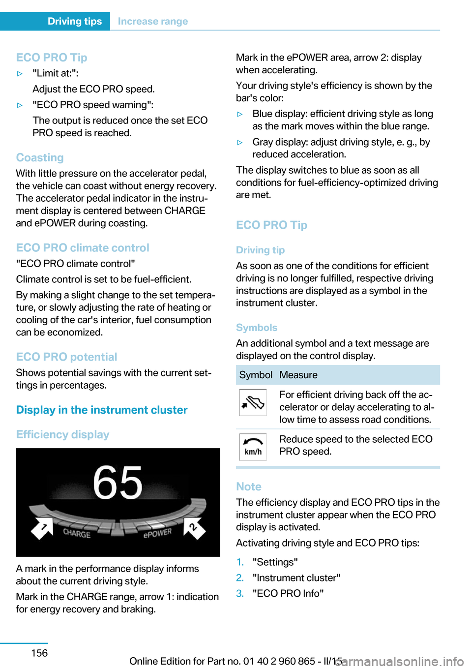
A mark in the performance display informs
about the current driving style.
Mark in the CHARGE range, arrow 1: indication
for energy recovery and braking.
Mark in the ePOWER area, arrow 2: display
when accelerating.
Your driving style's efficiency is shown by the
bar's color:▷Blue display: efficient driving style as long
as the mark moves within the blue range.▷Gray display: adjust driving style, e. g., by
reduced acceleration.
The display switches to blue as soon as all
conditions for fuel-efficiency-optimized driving
are met.
ECO PRO Tip Driving tip
As soon as one of the conditions for efficient
driving is no longer fulfilled, respective driving
instructions are displayed as a symbol in the
instrument cluster.
Symbols
An additional symbol and a text message are
displayed on the control display.
SymbolMeasureFor efficient driving back off the ac‐
celerator or delay accelerating to al‐
low time to assess road conditions.Reduce speed to the selected ECO
PRO speed.
Note
The efficiency display and ECO PRO tips in the
instrument cluster appear when the ECO PRO
display is activated.
Activating driving style and ECO PRO tips:
1."Settings"2."Instrument cluster"3."ECO PRO Info"Seite 156Driving tipsIncrease range156
Online Edition for Part no. 01 40 2 960 865 - II/15
Page 199 of 236
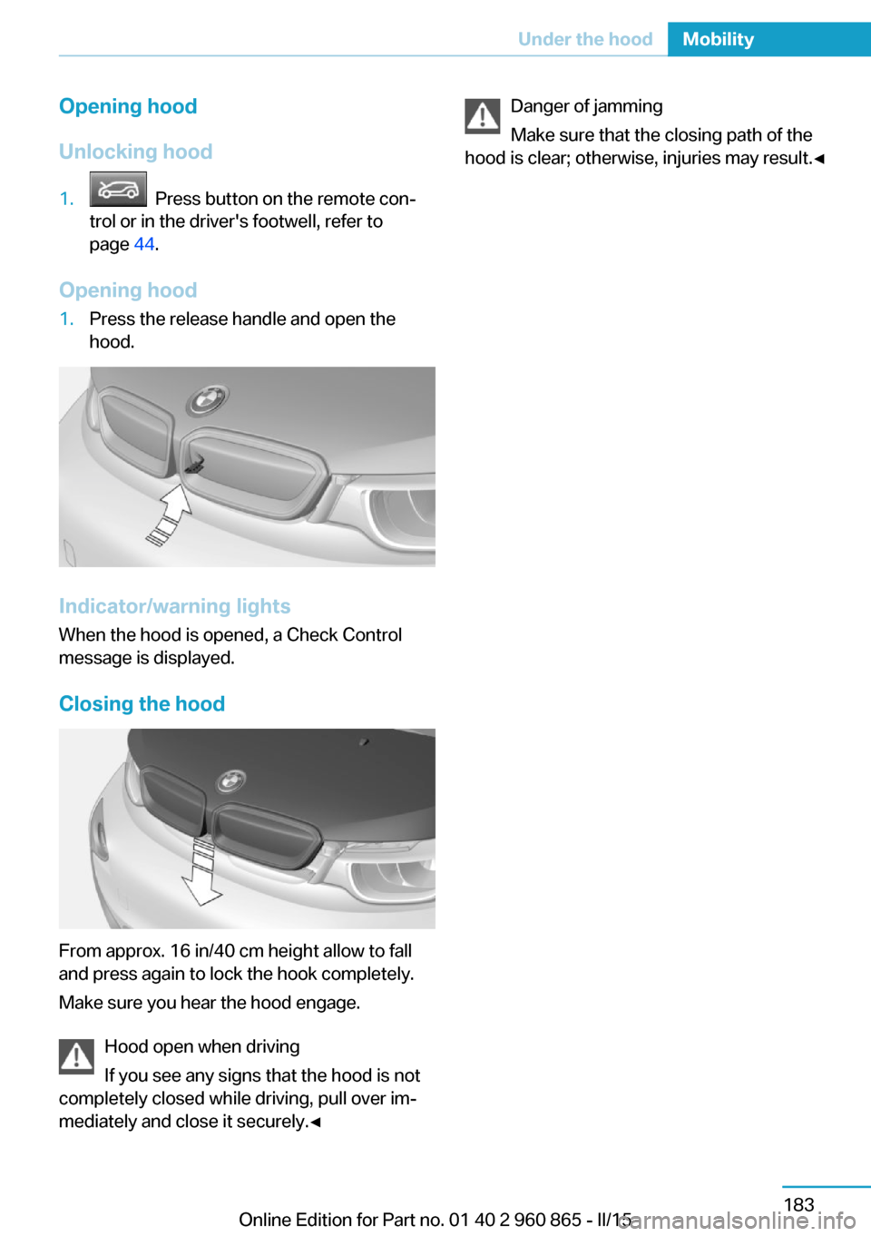
Opening hood
Unlocking hood1. Press button on the remote con‐
trol or in the driver's footwell, refer to
page 44.
Opening hood
1.Press the release handle and open the
hood.
Indicator/warning lights
When the hood is opened, a Check Control
message is displayed.
Closing the hood
From approx. 16 in/40 cm height allow to fall
and press again to lock the hook completely.
Make sure you hear the hood engage.
Hood open when driving
If you see any signs that the hood is not
completely closed while driving, pull over im‐
mediately and close it securely.◀
Danger of jamming
Make sure that the closing path of the
hood is clear; otherwise, injuries may result.◀Seite 183Under the hoodMobility183
Online Edition for Part no. 01 40 2 960 865 - II/15
Page 205 of 236
Service and Warranty
Information Booklet for US
models and Warranty and
Service Guide Booklet for
Canadian models
Please consult your Service and Warranty In‐
formation Booklet for US models and Warranty
and Service Guide Booklet for Canadian mod‐
els for additional information on service re‐
quirements.
Maintenance and repair should be performed
by your service center. Make sure to have reg‐
ular maintenance procedures recorded in the
vehicle's Service and Warranty Information
Booklet for US models, and in the Warranty
and Service Guide Booklet for Canadian mod‐
els. These entries are proof of regular mainte‐
nance.
Socket for OBD Onboard
Diagnosis
Note Socket for Onboard Diagnosis
The socket for onboard diagnostics may
only be used by the service center or a work‐
shop that operates in accordance with the
specifications of the vehicle manufacturer with
correspondingly trained personnel and other
authorized persons. Otherwise, use may result
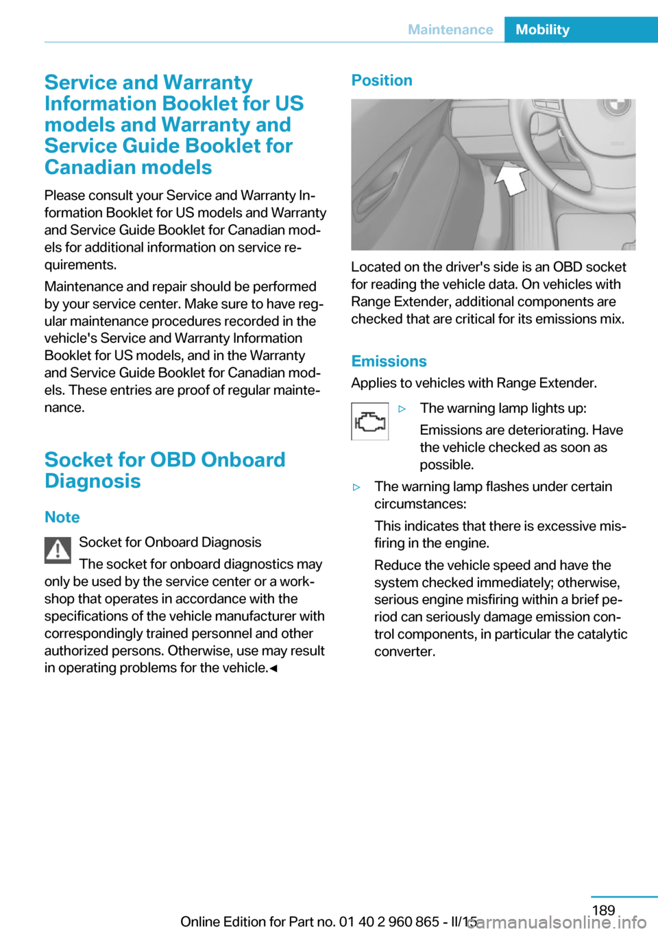
in operating problems for the vehicle.◀Position
Located on the driver's side is an OBD socket
for reading the vehicle data. On vehicles with
Range Extender, additional components are
checked that are critical for its emissions mix.
Emissions
Applies to vehicles with Range Extender.
▷The warning lamp lights up:
Emissions are deteriorating. Have
the vehicle checked as soon as
possible.▷The warning lamp flashes under certain
circumstances:
This indicates that there is excessive mis‐
firing in the engine.
Reduce the vehicle speed and have the
system checked immediately; otherwise,
serious engine misfiring within a brief pe‐
riod can seriously damage emission con‐
trol components, in particular the catalytic
converter.Seite 189MaintenanceMobility189
Online Edition for Part no. 01 40 2 960 865 - II/15
Page 212 of 236
Breakdown assistanceVehicle features and options
This chapter describes all standard, country-
specific and optional features offered with the
series. It also describes features that are not
necessarily available in your car, e. g., due to
the selected options or country versions. This
also applies to safety-related functions and
systems. The respectively applicable country
provisions must be observed when using the
respective features and systems.
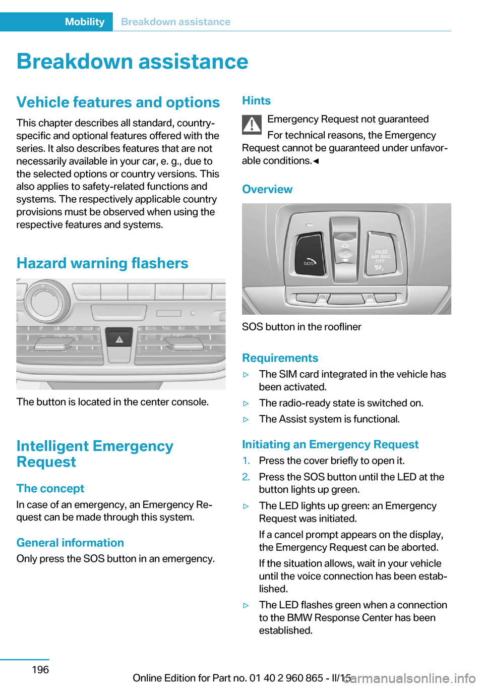
Hazard warning flashers
The button is located in the center console.
Intelligent Emergency
Request
The concept In case of an emergency, an Emergency Re‐
quest can be made through this system.
General information
Only press the SOS button in an emergency.
Hints
Emergency Request not guaranteed
For technical reasons, the Emergency
Request cannot be guaranteed under unfavor‐
able conditions.◀
Overview
SOS button in the roofliner
Requirements
▷The SIM card integrated in the vehicle has
been activated.▷The radio-ready state is switched on.▷The Assist system is functional.
Initiating an Emergency Request
1.Press the cover briefly to open it.2.Press the SOS button until the LED at the
button lights up green.▷The LED lights up green: an Emergency
Request was initiated.
If a cancel prompt appears on the display,
the Emergency Request can be aborted.
If the situation allows, wait in your vehicle
until the voice connection has been estab‐
lished.▷The LED flashes green when a connection
to the BMW Response Center has been
established.Seite 196MobilityBreakdown assistance196
Online Edition for Part no. 01 40 2 960 865 - II/15
Page 214 of 236
Transporting your vehicle
Note Your vehicle is not permitted to be towed.
Therefore, contact a service center in the
event of a breakdown.
Do not have the vehicle towed
Have your vehicle transported on a load‐
ing platform only; otherwise, damage may oc‐
cur.◀
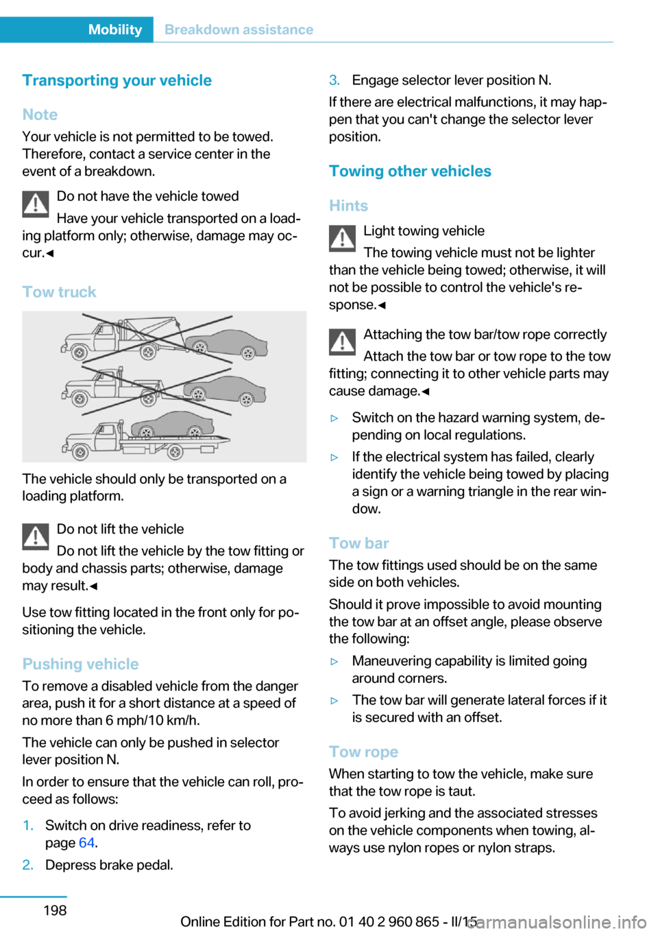
Tow truck
The vehicle should only be transported on a
loading platform.
Do not lift the vehicle
Do not lift the vehicle by the tow fitting or
body and chassis parts; otherwise, damage
may result.◀
Use tow fitting located in the front only for po‐
sitioning the vehicle.
Pushing vehicle To remove a disabled vehicle from the danger
area, push it for a short distance at a speed of
no more than 6 mph/10 km/h.
The vehicle can only be pushed in selector
lever position N.
In order to ensure that the vehicle can roll, pro‐
ceed as follows:
1.Switch on drive readiness, refer to
page 64.2.Depress brake pedal.3.Engage selector lever position N.
If there are electrical malfunctions, it may hap‐
pen that you can't change the selector lever
position.
Towing other vehicles
Hints Light towing vehicle
The towing vehicle must not be lighter
than the vehicle being towed; otherwise, it will
not be possible to control the vehicle's re‐
sponse.◀
Attaching the tow bar/tow rope correctly
Attach the tow bar or tow rope to the tow
fitting; connecting it to other vehicle parts may
cause damage.◀
▷Switch on the hazard warning system, de‐
pending on local regulations.▷If the electrical system has failed, clearly
identify the vehicle being towed by placing
a sign or a warning triangle in the rear win‐
dow.
Tow bar
The tow fittings used should be on the same
side on both vehicles.
Should it prove impossible to avoid mounting
the tow bar at an offset angle, please observe
the following:
▷Maneuvering capability is limited going
around corners.▷The tow bar will generate lateral forces if it
is secured with an offset.
Tow rope
When starting to tow the vehicle, make sure
that the tow rope is taut.
To avoid jerking and the associated stresses
on the vehicle components when towing, al‐
ways use nylon ropes or nylon straps.
Seite 198MobilityBreakdown assistance198
Online Edition for Part no. 01 40 2 960 865 - II/15
Page 226 of 236
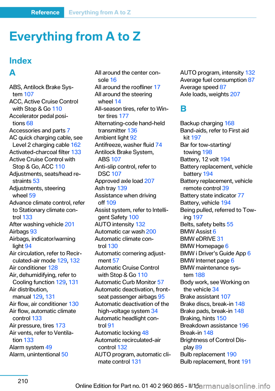
Everything from A to Z
IndexA ABS, Antilock Brake Sys‐ tem 107
ACC, Active Cruise Control with Stop & Go 110
Accelerator pedal posi‐ tions 68
Accessories and parts 7
AC quick charging cable, see Level 2 charging cable 162
Activated-charcoal filter 133
Active Cruise Control with Stop & Go, ACC 110
Adjustments, seats/head re‐ straints 53
Adjustments, steering wheel 59
Advance climate control, refer to Stationary climate con‐
trol 133
After washing vehicle 201
Airbags 93
Airbags, indicator/warning light 94
Air circulation, refer to Recir‐ culated-air mode 129, 132
Air conditioner 128
Air, dehumidifying, refer to Cooling function 129, 131
Air distribution, manual 129, 131
Air flow, air conditioner 130
Air flow, automatic climate control 133
Air pressure, tires 173
Air vents, refer to Ventila‐ tion 133
Alarm system 49
Alarm, unintentional 50 All around the center con‐
sole 16
All around the roofliner 17
All around the steering wheel 14
All-season tires, refer to Win‐ ter tires 177
Alternating-code hand-held transmitter 136
Ambient light 92
Antifreeze, washer fluid 74
Antilock Brake System, ABS 107
Anti-slip control, refer to DSC 107
Approved axle load 207
Ash tray 139
Assistance when driving off 109
Assist system, refer to Intelli‐ gent Safety 100
AUTO intensity 132
Automatic car wash 200
Automatic climate con‐ trol 130
Automatic cornering adjust‐ ment 57
Automatic Cruise Control with Stop & Go 110
Automatic Curb Monitor 57
Automatic deactivation, front- seat passenger airbags 95
Automatic deactivation of the high-voltage system 34
Automatic headlight con‐ trol 91
Automatic locking 48
Automatic recirculated-air control 132
AUTO program, automatic cli‐ mate control 131 AUTO program, intensity 132
Average fuel consumption 87
Average speed 87
Axle loads, weights 207
B Backup charging 168
Band-aids, refer to First aid kit 197
Bar for tow-starting/ towing 198
Battery, 12 volt 194
Battery replacement, vehicle battery 194
Battery replacement, vehicle remote control 39
Battery state indicator 77
Battery, vehicle 194
Being pulled, referred to Tow‐ ing 197
Belts, safety belts 55
BMW Assist 6
BMW eDRIVE 31
BMW Homepage 6
BMW i Driver’s Guide App 6
BMW Internet page 6
BMW maintenance sys‐ tem 188
Body work, see Working on the vehicle 34
Brake assistant 107
Brake discs, break-in 148
Brake pads, break-in 148
Braking, hints 150
Breakdown assistance 196
Break-in 148
Brightness of Control Dis‐ play 89
Bulb replacement 190
Bulb replacement, front 191 Seite 210ReferenceEverything from A to Z210
Online Edition for Part no. 01 40 2 960 865 - II/15
Page 227 of 236
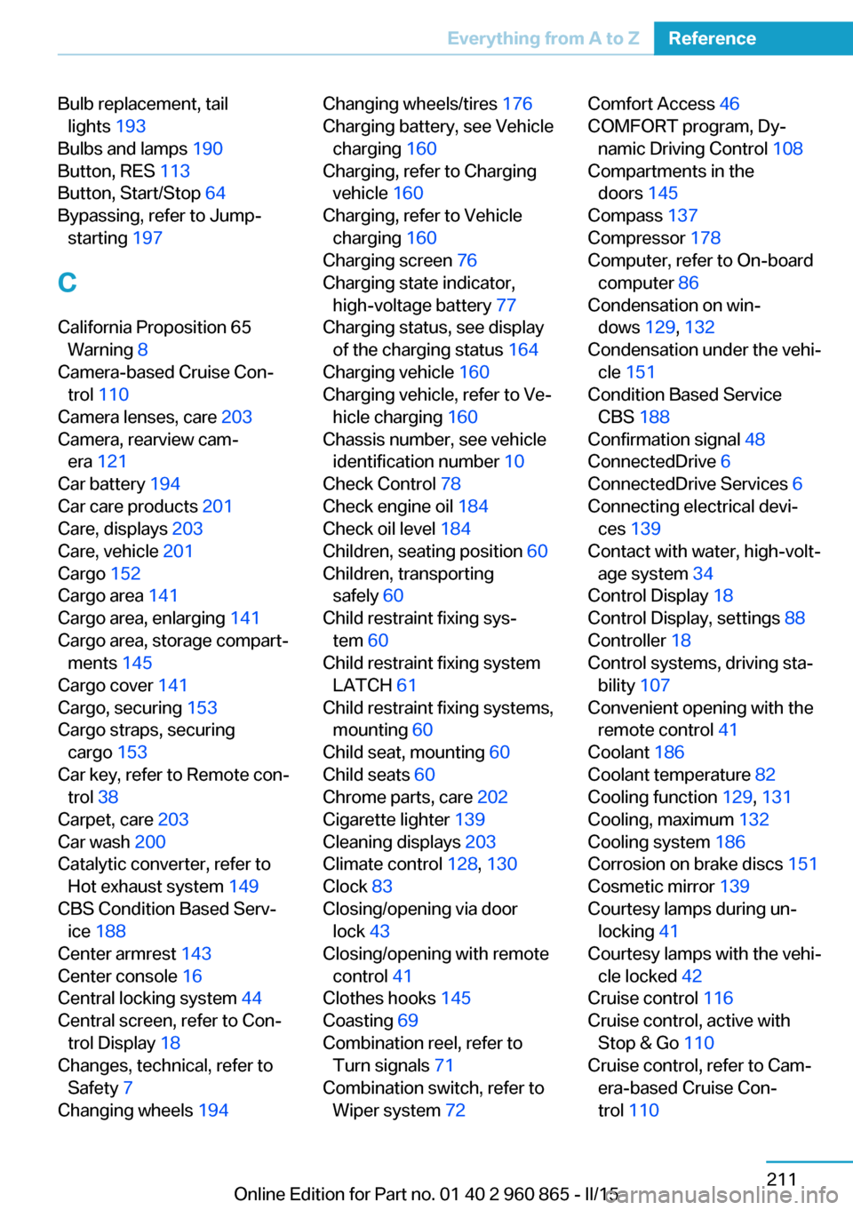
Bulb replacement, taillights 193
Bulbs and lamps 190
Button, RES 113
Button, Start/Stop 64
Bypassing, refer to Jump- starting 197
C
California Proposition 65 Warning 8
Camera-based Cruise Con‐ trol 110
Camera lenses, care 203
Camera, rearview cam‐ era 121
Car battery 194
Car care products 201
Care, displays 203
Care, vehicle 201
Cargo 152
Cargo area 141
Cargo area, enlarging 141
Cargo area, storage compart‐ ments 145
Cargo cover 141
Cargo, securing 153
Cargo straps, securing cargo 153
Car key, refer to Remote con‐ trol 38
Carpet, care 203
Car wash 200
Catalytic converter, refer to Hot exhaust system 149
CBS Condition Based Serv‐ ice 188
Center armrest 143
Center console 16
Central locking system 44
Central screen, refer to Con‐ trol Display 18
Changes, technical, refer to Safety 7
Changing wheels 194 Changing wheels/tires 176
Charging battery, see Vehicle charging 160
Charging, refer to Charging vehicle 160
Charging, refer to Vehicle charging 160
Charging screen 76
Charging state indicator, high-voltage battery 77
Charging status, see display of the charging status 164
Charging vehicle 160
Charging vehicle, refer to Ve‐ hicle charging 160
Chassis number, see vehicle identification number 10
Check Control 78
Check engine oil 184
Check oil level 184
Children, seating position 60
Children, transporting safely 60
Child restraint fixing sys‐ tem 60
Child restraint fixing system LATCH 61
Child restraint fixing systems, mounting 60
Child seat, mounting 60
Child seats 60
Chrome parts, care 202
Cigarette lighter 139
Cleaning displays 203
Climate control 128, 130
Clock 83
Closing/opening via door lock 43
Closing/opening with remote control 41
Clothes hooks 145
Coasting 69
Combination reel, refer to Turn signals 71
Combination switch, refer to Wiper system 72 Comfort Access 46
COMFORT program, Dy‐ namic Driving Control 108
Compartments in the doors 145
Compass 137
Compressor 178
Computer, refer to On-board computer 86
Condensation on win‐ dows 129, 132
Condensation under the vehi‐ cle 151
Condition Based Service CBS 188
Confirmation signal 48
ConnectedDrive 6
ConnectedDrive Services 6
Connecting electrical devi‐ ces 139
Contact with water, high-volt‐ age system 34
Control Display 18
Control Display, settings 88
Controller 18
Control systems, driving sta‐ bility 107
Convenient opening with the remote control 41
Coolant 186
Coolant temperature 82
Cooling function 129, 131
Cooling, maximum 132
Cooling system 186
Corrosion on brake discs 151
Cosmetic mirror 139
Courtesy lamps during un‐ locking 41
Courtesy lamps with the vehi‐ cle locked 42
Cruise control 116
Cruise control, active with Stop & Go 110
Cruise control, refer to Cam‐ era-based Cruise Con‐
trol 110 Seite 211Everything from A to ZReference211
Online Edition for Part no. 01 40 2 960 865 - II/15