socket BMW I3 2015 I01 Owner's Manual
[x] Cancel search | Manufacturer: BMW, Model Year: 2015, Model line: I3, Model: BMW I3 2015 I01Pages: 236, PDF Size: 17.6 MB
Page 96 of 236
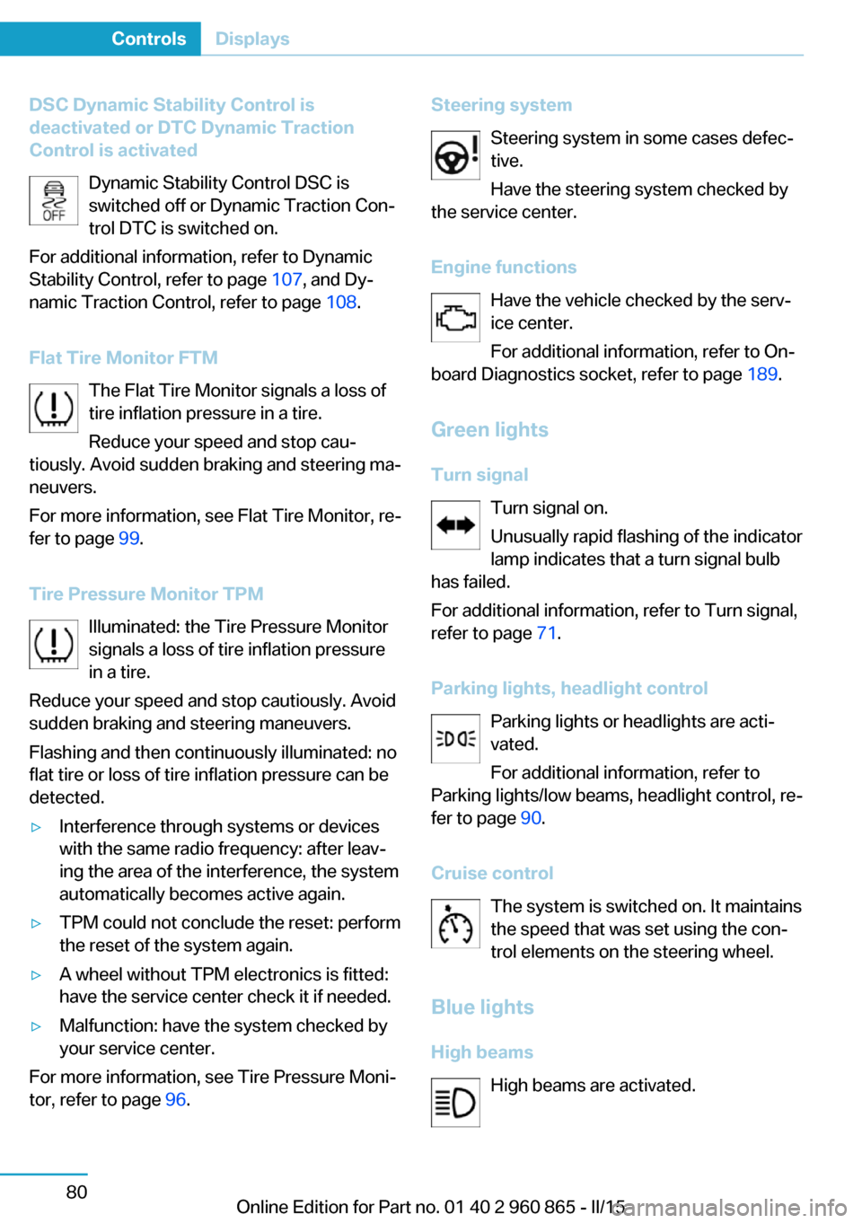
DSC Dynamic Stability Control is
deactivated or DTC Dynamic Traction
Control is activated
Dynamic Stability Control DSC is
switched off or Dynamic Traction Conā
trol DTC is switched on.
For additional information, refer to Dynamic
Stability Control, refer to page 107, and Dyā
namic Traction Control, refer to page 108.
Flat Tire Monitor FTM The Flat Tire Monitor signals a loss of
tire inflation pressure in a tire.
Reduce your speed and stop cauā
tiously. Avoid sudden braking and steering maā
neuvers.
For more information, see Flat Tire Monitor, reā
fer to page 99.
Tire Pressure Monitor TPM Illuminated: the Tire Pressure Monitor
signals a loss of tire inflation pressure
in a tire.
Reduce your speed and stop cautiously. Avoid
sudden braking and steering maneuvers.
Flashing and then continuously illuminated: no
flat tire or loss of tire inflation pressure can be
detected.ā·Interference through systems or devices
with the same radio frequency: after leavā
ing the area of the interference, the system
automatically becomes active again.ā·TPM could not conclude the reset: perform
the reset of the system again.ā·A wheel without TPM electronics is fitted:
have the service center check it if needed.ā·Malfunction: have the system checked by
your service center.
For more information, see Tire Pressure Moniā
tor, refer to page 96.
Steering system
Steering system in some cases defecātive.
Have the steering system checked by
the service center.
Engine functions Have the vehicle checked by the servāice center.
For additional information, refer to On-
board Diagnostics socket, refer to page 189.
Green lights Turn signal Turn signal on.
Unusually rapid flashing of the indicator
lamp indicates that a turn signal bulb
has failed.
For additional information, refer to Turn signal,
refer to page 71.
Parking lights, headlight control Parking lights or headlights are actiā
vated.
For additional information, refer to
Parking lights/low beams, headlight control, reā
fer to page 90.
Cruise control The system is switched on. It maintains
the speed that was set using the conā
trol elements on the steering wheel.
Blue lights
High beams High beams are activated.Seite 80ControlsDisplays80
Online Edition for Part no. 01 40 2 960 865 - II/15
Page 155 of 236

Settings are stored automatically after approxiā
mately 10 seconds.
Sun visor
Glare shield Fold the sun visor down or up.
Vanity mirror A vanity mirror is located in the sun visor beā
hind a cover. When the cover is opened, the
mirror lighting switches on.
Ashtray/cigarette lighterAshtray
Overview
The ashtray can be inserted in the cupholder.
Emptying Take out the insert.
Lighter Danger of burns
Only hold the hot lighter by its knob; othā
erwise, there is a danger of getting burned.
Switch off operating readiness and take the reā
mote control with you when leaving the vehicle
so that children cannot use the lighter and
burn themselves.ā
Replace the cover after use
Reinsert the lighter or socket cover after
use, otherwise objects may get into the lighter
socket or fixture and cause a short circuit.ā
Overview
The cigarette lighter is located between the
front seats.
Push in the lighter.
The lighter can be removed as
soon as it pops back out.
Connecting electrical devices
Hints Do not connect charging devices to the
12 volt socket in the vehicle
Do not connect battery chargers to the facā
tory-installed 12 volt sockets in the vehicle as
this may damage the vehicle battery due to an
increased power consumption.ā
Replace the cover after use
Reinsert the lighter or socket cover after
use, otherwise objects may get into the lighter
socket or fixture and cause a short circuit.ā
Seite 139Interior equipmentControls139
Online Edition for Part no. 01 40 2 960 865 - II/15
Page 156 of 236
Sockets
General information
The lighter socket can be used as a socket for
electrical equipment when operating and drive
readiness are activated.
Note
The total load of all sockets must not exceed
140 watts at 12 volts.
Do not damage the socket by using unsuitable
connectors.
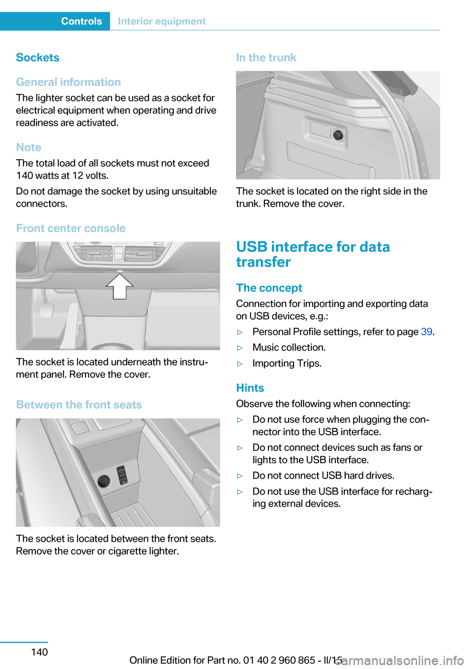
Front center console
The socket is located underneath the instruā
ment panel. Remove the cover.
Between the front seats
The socket is located between the front seats.
Remove the cover or cigarette lighter.
In the trunk
The socket is located on the right side in the
trunk. Remove the cover.
USB interface for data
transfer
The concept Connection for importing and exporting data
on USB devices, e.g.:
ā·Personal Profile settings, refer to page 39.ā·Music collection.ā·Importing Trips.
Hints
Observe the following when connecting:
ā·Do not use force when plugging the conā
nector into the USB interface.ā·Do not connect devices such as fans or
lights to the USB interface.ā·Do not connect USB hard drives.ā·Do not use the USB interface for rechargā
ing external devices.Seite 140ControlsInterior equipment140
Online Edition for Part no. 01 40 2 960 865 - II/15
Page 157 of 236
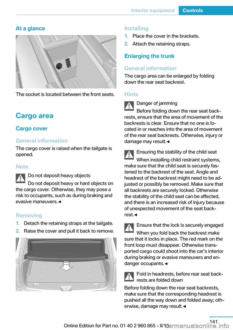
At a glance
The socket is located between the front seats.
Cargo area
Cargo cover
General information The cargo cover is raised when the tailgate is
opened.
Note Do not deposit heavy objects
Do not deposit heavy or hard objects on
the cargo cover. Otherwise, they may pose a
risk to occupants, such as during braking and
evasive maneuvers.ā
Removing
1.Detach the retaining straps at the tailgate.2.Raise the cover and pull it back to remove.Installing1.Place the cover in the brackets.2.Attach the retaining straps.
Enlarging the trunk
General information
The cargo area can be enlarged by folding
down the rear seat backrest.
Hints Danger of jamming
Before folding down the rear seat backā
rests, ensure that the area of movement of the
backrests is clear. Ensure that no one is loā
cated in or reaches into the area of movement
of the rear seat backrests. Otherwise, injury or
damage may result.ā
Ensuring the stability of the child seat
When installing child restraint systems,
make sure that the child seat is securely fasā
tened to the backrest of the seat. Angle and
headrest of the backrest might need to be adā
justed or possibly be removed. Make sure that
all backrests are securely locked. Otherwise
the stability of the child seat can be affected,
and there is an increased risk of injury because
of unexpected movement of the seat backā
rest.ā
Ensure that the lock is securely engaged
When you fold back the backrest make
sure that it locks in place. The red mark on the
front loop must disappear. Otherwise transā
ported cargo could shoot into the car's interior
during braking or evasive maneuvers and enā
danger occupants.ā
Fold in headrests, before rear seat backā
rests are folded down
Before folding down the rear seat backrests,
make sure that the corresponding headrest is
pushed all the way down and folded away; othā
erwise, damage may result.ā
Seite 141Interior equipmentControls141
Online Edition for Part no. 01 40 2 960 865 - II/15
Page 176 of 236
Charging vehicleVehicle features and options
This chapter describes all standard, country-
specific and optional features offered with the
series. It also describes features that are not
necessarily available in your car, e. g., due to
the selected options or country versions. This
also applies to safety-related functions and
systems. The respectively applicable country
provisions must be observed when using the
respective features and systems.
The concept
The vehicle can be charged using various
charging cables at charging stations or housā
hold sockets. Control and monitoring of the
charging process are handled completely auā
tomatically. The charge current strength can
be set by means of the Control Display.
General information High-voltage batteryThe high-voltage battery is used as an energy
accumulator. The high-voltage battery can be
charged by energy recovery during the trip or
via the power grid.
When charging via the power grid, you can
chose between the following variants.ā·Level 1 charging via a household socket.ā·Level 2 charging via a Level 2 charging staā
tion.ā·Charging via a DC charging station.
Level 1 charging is possible via a household
socket within a voltage range of 100 volts to
240 volts.
For optimal use of the energy from the power
grid, charging at a Level 2 charging station,
such as BMW i Wallbox, is recommended.
Charge current
The charge current strength is indicated in amā
peres.
The vehicle cannot automatically detect the
maximum permissible charge current strength
of the power grid during charging via a houseā
hold socket or charging station.
Level 1 charging Prior to the first Level 1 charging at your own
household socket, as well as when charging at external electrical power sockets in Level 1,
the allowed charge current strength must be
determined, e.g. by a qualified electrician.
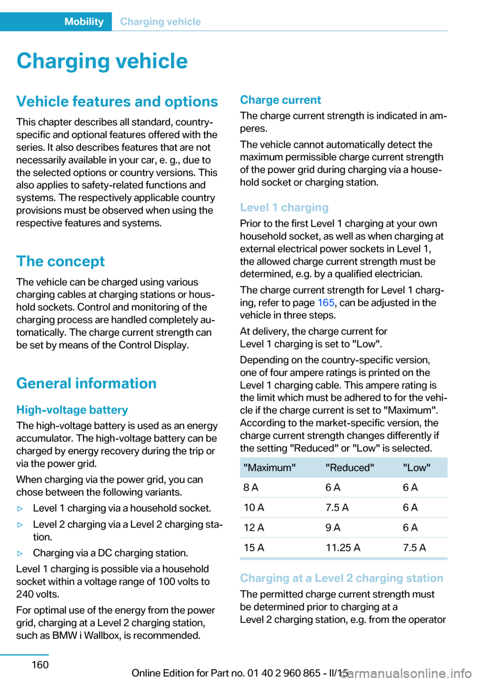
The charge current strength for Level 1 chargā
ing, refer to page 165, can be adjusted in the
vehicle in three steps.
At delivery, the charge current for
Level 1 charging is set to "Low".
Depending on the country-specific version,
one of four ampere ratings is printed on the
Level 1 charging cable. This ampere rating is
the limit which must be adhered to for the vehiā
cle if the charge current is set to "Maximum".
According to the market-specific version, the
charge current strength changes differently if
the setting "Reduced" or "Low" is selected."Maximum""Reduced""Low"8 A6 A6 A10 A7.5 A6 A12 A9 A6 A15 A11.25 A7.5 A
Charging at a Level 2 charging station
The permitted charge current strength must
be determined prior to charging at a
Level 2 charging station, e.g. from the operator
Seite 160MobilityCharging vehicle160
Online Edition for Part no. 01 40 2 960 865 - II/15
Page 177 of 236
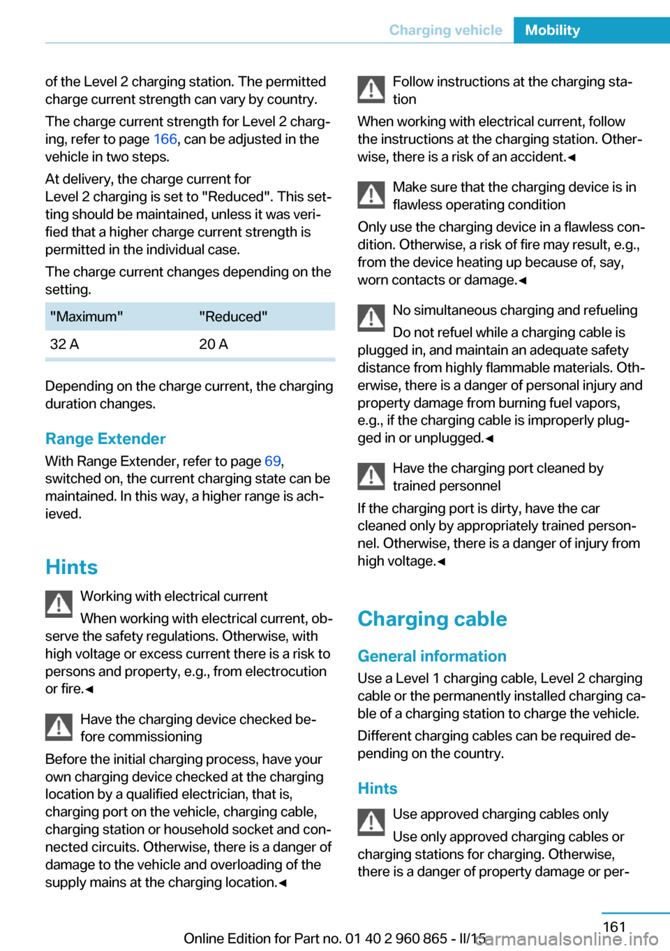
of the Level 2 charging station. The permitted
charge current strength can vary by country.
The charge current strength for Level 2 chargā
ing, refer to page 166, can be adjusted in the
vehicle in two steps.
At delivery, the charge current for
Level 2 charging is set to "Reduced". This setā
ting should be maintained, unless it was veriā
fied that a higher charge current strength is
permitted in the individual case.
The charge current changes depending on the
setting."Maximum""Reduced"32 A20 A
Depending on the charge current, the charging
duration changes.
Range Extender
With Range Extender, refer to page 69,
switched on, the current charging state can be
maintained. In this way, a higher range is achā
ieved.
Hints Working with electrical current
When working with electrical current, obā
serve the safety regulations. Otherwise, with
high voltage or excess current there is a risk to
persons and property, e.g., from electrocution or fire.ā
Have the charging device checked beā
fore commissioning
Before the initial charging process, have your
own charging device checked at the charging location by a qualified electrician, that is,
charging port on the vehicle, charging cable,
charging station or household socket and conā
nected circuits. Otherwise, there is a danger of
damage to the vehicle and overloading of the
supply mains at the charging location.ā
Follow instructions at the charging staā
tion
When working with electrical current, follow
the instructions at the charging station. Otherā
wise, there is a risk of an accident.ā
Make sure that the charging device is in
flawless operating condition
Only use the charging device in a flawless conā
dition. Otherwise, a risk of fire may result, e.g.,
from the device heating up because of, say,
worn contacts or damage.ā
No simultaneous charging and refueling
Do not refuel while a charging cable is
plugged in, and maintain an adequate safety
distance from highly flammable materials. Othā
erwise, there is a danger of personal injury and
property damage from burning fuel vapors,
e.g., if the charging cable is improperly plugā
ged in or unplugged.ā
Have the charging port cleaned by
trained personnel
If the charging port is dirty, have the car
cleaned only by appropriately trained personā
nel. Otherwise, there is a danger of injury from high voltage.ā
Charging cable General information
Use a Level 1 charging cable, Level 2 charging
cable or the permanently installed charging caā
ble of a charging station to charge the vehicle.
Different charging cables can be required deā pending on the country.
Hints Use approved charging cables only
Use only approved charging cables or
charging stations for charging. Otherwise,
there is a danger of property damage or perāSeite 161Charging vehicleMobility161
Online Edition for Part no. 01 40 2 960 865 - II/15
Page 178 of 236
sonal injury, e.g., from burning cables. Informaā
tion about the approved charging cables can
be obtained from the service center.ā
Use the charging cable only for charging
the vehicle, and do not extend it
Use the charging cable only for charging the
vehicle and do not extend it with cables or
adapters. Otherwise, it may not be possible to
complete the charging process or property
damage might occur, e.g., due to a cable fire.ā
Do not use any damaged charging cables
Do not use any damaged charging caā
bles. Otherwise, there is a risk of injury from
high voltage.ā
Level 1 charging cable With the Level 1 charging cable, it is permissiā
ble to perform charging from grounded houseā
hold sockets. At the power connection of a
household socket, charging is done with alterā
nating current.
When a Level 1 charging cable is used, this
may produce efficiency values other than indiā
cated on the energy label.
Level 2 charging cable
The Level 2 charging cable makes it possible
to recharge at sockets of designated
Level 2 charging stations using a special plug.
Charging is performed with alternating current
at designated Level 2 charging stations. The
charging process can be completed faster than
at household sockets.
If necessary, the charging cable is attached to
the charging station.
If a Level 2 charging cable is used, apply the
corresponding setting on the Control Display,
refer to page 166.
DC charging cable The DC charging cable that is permanently inā
stalled at the charging station makes is possiāble to charge at DC charging stations. Chargā
ing is performed with direct current at
designated DC charging stations. At the higher
lidacity current connection of a DC charger
station the charging time is significantly lower
than with a household socket or a level 2
charging station.
During charging at a DC charging station, an
indication in the instrument cluster, refer to
page 166, is displayed.
Storage
The Level 1 charging cable is located in the caā
ble compartment under the hood.
The Level 2 charging cable can be stored in
the same place.
Moisture can penetrate into the occasional use
cable compartment, e.g. in a car wash.
If required, store the charging cable with the
installed plug cover to prevent moisture in the
charging cable plug.Seite 162MobilityCharging vehicle162
Online Edition for Part no. 01 40 2 960 865 - II/15
Page 179 of 236
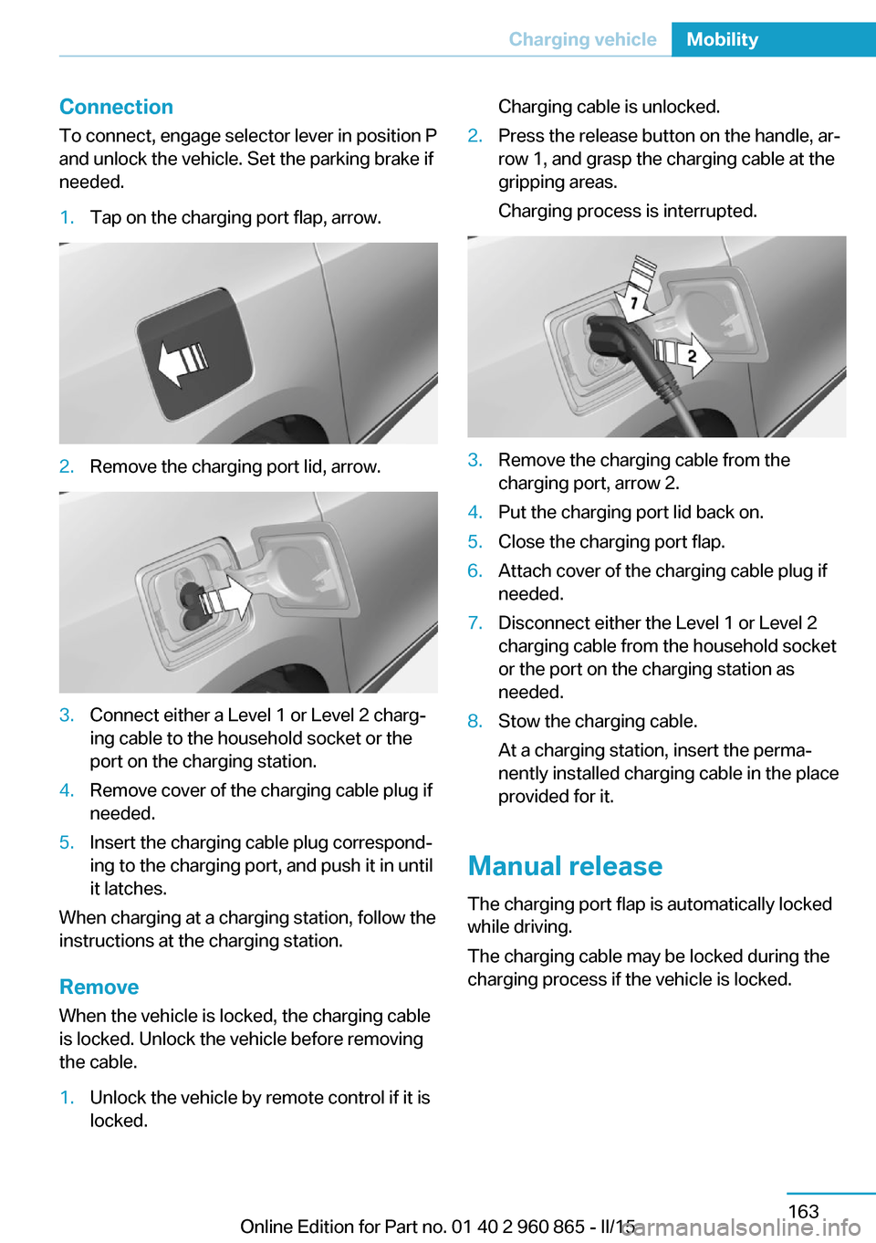
ConnectionTo connect, engage selector lever in position P
and unlock the vehicle. Set the parking brake if
needed.1.Tap on the charging port flap, arrow.2.Remove the charging port lid, arrow.3.Connect either a Level 1 or Level 2 chargā
ing cable to the household socket or the
port on the charging station.4.Remove cover of the charging cable plug if
needed.5.Insert the charging cable plug correspondā
ing to the charging port, and push it in until
it latches.
When charging at a charging station, follow the
instructions at the charging station.
Remove
When the vehicle is locked, the charging cable
is locked. Unlock the vehicle before removing
the cable.
1.Unlock the vehicle by remote control if it is
locked.Charging cable is unlocked.2.Press the release button on the handle, arā
row 1, and grasp the charging cable at the
gripping areas.
Charging process is interrupted.3.Remove the charging cable from the
charging port, arrow 2.4.Put the charging port lid back on.5.Close the charging port flap.6.Attach cover of the charging cable plug if
needed.7.Disconnect either the Level 1 or Level 2
charging cable from the household socket
or the port on the charging station as
needed.8.Stow the charging cable.
At a charging station, insert the permaā
nently installed charging cable in the place
provided for it.
Manual release
The charging port flap is automatically locked
while driving.
The charging cable may be locked during the
charging process if the vehicle is locked.
Seite 163Charging vehicleMobility163
Online Edition for Part no. 01 40 2 960 865 - II/15
Page 180 of 236
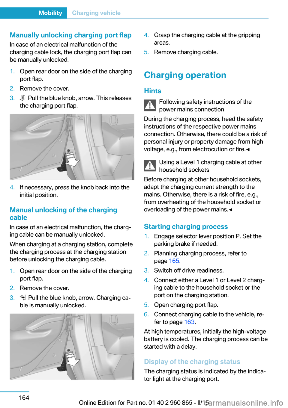
Manually unlocking charging port flapIn case of an electrical malfunction of the
charging cable lock, the charging port flap can
be manually unlocked.1.Open rear door on the side of the charging
port flap.2.Remove the cover.3. Pull the blue knob, arrow. This releases
the charging port flap.4.If necessary, press the knob back into the
initial position.
Manual unlocking of the charging
cable
In case of an electrical malfunction, the chargā
ing cable can be manually unlocked.
When charging at a charging station, complete
the charging process at the charging station
before unlocking the charging cable.
1.Open rear door on the side of the charging
port flap.2.Remove the cover.3. Pull the blue knob, arrow. Charging caā
ble is manually unlocked.4.Grasp the charging cable at the gripping
areas.5.Remove charging cable.
Charging operation
Hints Following safety instructions of the
power mains connection
During the charging process, heed the safety
instructions of the respective power mains
connection. Otherwise, there could be a risk of
personal injury or property damage from high
voltage, e.g., from electrocution or fire.ā
Using a Level 1 charging cable at other
household sockets
Before charging at other household sockets,
adapt the charging current strength to the
mains. Otherwise, there is a risk of fire, e.g.,
from overheating of the household socket or
overloading of the power mains.ā
Starting charging process
1.Engage selector lever position P. Set the
parking brake if needed.2.Planning charging process, refer to
page 165.3.Switch off drive readiness.4.Connect either a Level 1 or Level 2 chargā
ing cable to the household socket or the
port on the charging station.5.Open charging port flap.6.Connect charging cable to the vehicle, reā
fer to page 163.
At high temperatures, initially the high-voltage
battery is cooled. The charging process can be
started with a delay.
Display of the charging status
The charging status is indicated by the indicaā
tor light at the charging port.
Seite 164MobilityCharging vehicle164
Online Edition for Part no. 01 40 2 960 865 - II/15
Page 182 of 236
3."AC charging power:"
Settings are stored. When you change chargā
ing locations you also might need to change
the setting for charging.
Set the charge current strength at other
household sockets to "Low".
Setting charging via a
Level 2 charging cable
Depending on the electrical mains, the vehicle
must be charged with a different charging curā
rent strength, refer to page 160.
When charging with a Level 2 charging cable,
the charging process can be completed faster
at a Level 2 charging station.
1."Settings"2."Charging"3."Level 2:"
Settings are stored. When you change chargā
ing locations you also might need to change
the setting for charging.
Stopping charging process The charging operation can be stopped at any
time by removing the charging cable and conā
tinued at a later time by connecting the chargā
ing cable in order to use other loads on the
power connection or to prevent simultaneous
high power from multiple loads.
The charging operation is interrupted when the
vehicle is unlocked and automatically resumed
after a brief time or when it is locked.
Continue charging operation If the charging operation is interrupted, e.g.,
through a temporary power failure, the chargā
ing operation is automatically continued after
the interruption.
Terminating charging process1.Removing the charging cable from the veā
hicle, refer to page 163.2.Stow the charging cable as required.3.Close the charging port flap.4.Lock vehicle if it is unlocked.
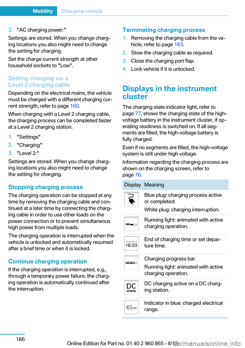
Displays in the instrument
cluster
The charging state indicator light, refer to page 77, shows the charging state of the high-
voltage battery in the instrument cluster, if opā
erating readiness is switched on. If all segā
ments are filled, the high-voltage battery is
fully charged.
Even if no segments are filled, the high-voltage
system is still under high voltage.
Information regarding the charging process are
shown on the charging screen, refer to
page 76.
DisplayMeaningBlue plug: charging process active
or completed.
White plug: charging interruption.Running light: animated with active
charging operation.End of charging time or set deparā
ture time.Charging progress bar.
Running light: animated with active
charging operation.DC charging active on a DC chargā
ing station.Indicator in blue: charged electrical
range.Seite 166MobilityCharging vehicle166
Online Edition for Part no. 01 40 2 960 865 - II/15