warning BMW M3 1992 E36 Workshop Manual
[x] Cancel search | Manufacturer: BMW, Model Year: 1992, Model line: M3, Model: BMW M3 1992 E36Pages: 759
Page 458 of 759
640-12
HEATING
AND
AIR
CONDITIONING
A/C
Compressor,
replacing
1
.
Followingmanufacturer's
instructions,
connectanap-
proved
refrigerant
recovery/recycling/recharging
unit
to
A/C
system
and
discharge
system
.
WARNING
-
Do
notdischarge%harge
the
AIC
system
without
proper
equipment
and
training
.
Damage
to
the
vehi-
cle
and
personal
injury
may
result
.
2
.
Remove
splash
shield
fromunder
engine
.
3
.
Mark
A/C
drive
belt
with
direction
ofrotation
.
Remove
A/C
belt
tensioner
trim
cap
.
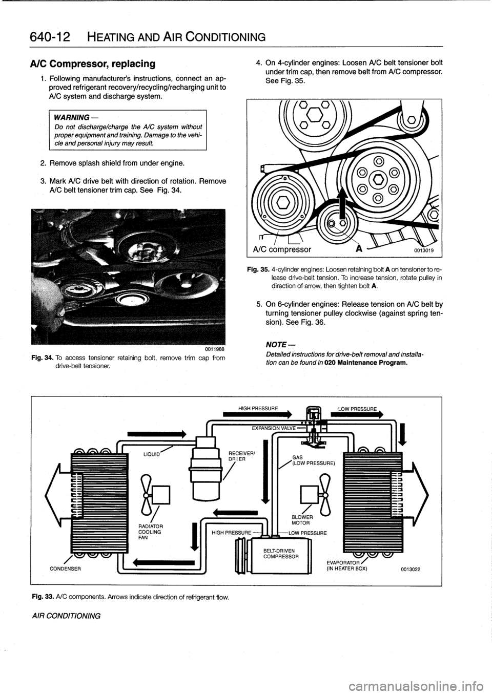
See
Fig
.
34
.
0011988
Fig
.
34
.
To
access
tensioner
retaining
bolt,
remove
trim
cap
from
drive-belt
tensioner
.
Fig
.
33
.
A/
C
components
.
Arrows
indicatedirection
of
refrigerant
flow
.
AIR
CONDITIONING
4
.
On
4-cylinder
engines
:
Loosen
A/C
belt
tensioner
bolt
under
trim
cap,
then
remove
belt
from
A/C
compressor
.
See
Fig
.
35
.
~=1
A/C
compressor
A
0013019
Fig
.
35
.
4-cylinder
engines
:
Loosen
retaining
bolt
A
on
tensionerto
re-
lease
drive-belt
tension
.
To
increase
tension,
rotate
pulley
in
direction
of
arrow,
then
tighten
bolt
A
.
5
.
On
6-cylinder
engines
:
Release
tension
on
A/C
belt
by
turning
tensioner
pulley
clockwíse
(againstspring
ten-
sion)
.
See
Fig
.
36
.
NOTE
-
Detailed
instructions
for
drive-belt
removal
and
installa-tion
can
be
found
in
020
Maintenance
Program
.
Page 460 of 759
640-14
HEATING
AND
AIR
CONDITIONING
7
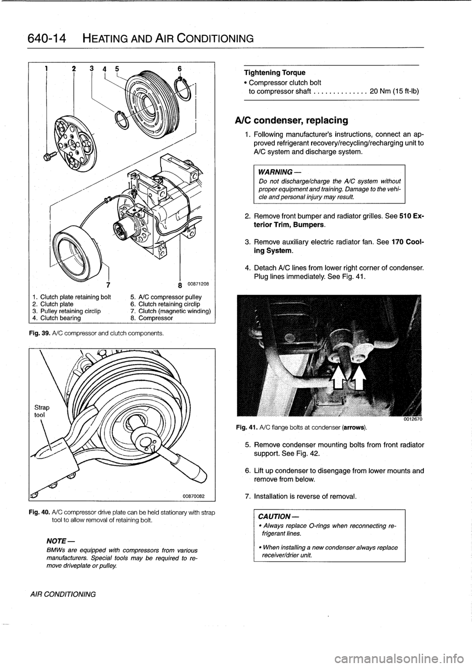
Fig
.
39
.
A/
C
compressorand
clutch
components
.
8
00871208
1.
Clutch
plate
retaining
bolt
5
.
A/C
compressor
pulley
2
.
Clutch
plate
6
.
Clutch
retaining
circlip
3
.
Pulley
retaining
circlip
7
.
Clutch
(magnetic
winding)
4
.
Clutch
bearing
8
.
Compressor
00870082
Fig
.
40
.
A/
C
compressor
driveplate
canbe
held
stationary
with
strap
toolto
allow
removal
of
retaining
bolt
.
NOTE-
BMWs
are
equipped
with
compressors
from
various
manufacturers
.
Special
tools
may
be
required
tore-
move
driveplate
orpulley
.
AIR
CONDITIONING
Tightening
Torque
"
Compressor
clutch
bolt
to
compressor
shaft
.....
.
....
..
.
.
20
Nm
(15
ft-Ib)
A/C
condenser,
replacing
1
.
Following
manufacturer's
instructions,
connect
an
ap-
proved
refrigerant
recovery/recycling/recharging
unitto
A/Csystemand
discharge
system
.
WARNING
-
Do
not
dischargelcharge
the
AIC
system
without
proper
equipment
and
training
.
Damage
to
the
vehi-
cle
and
personal
injury
may
result
.
2
.
Remove
front
bumper
and
radiator
grilles
.
See510
Ex-
terior
Trim,
Bumpers
.
3
.
Remove
auxiliary
electric
radiator
fan
.
See
170
Cool-
ing
System
.
4
.
DetachA/C
lines
from
lower
right
corner
of
condenser
.
Plug
lines
immediately
.
See
Fig
.
41
.
Fig
.
41
.
A/
C
flange
bolts
at
condenser
(arrows)
.
5
.
Remove
condenser
mounting
bolts
from
frontradiator
support
.
See
Fig
.
42
.
6
.
Lift
up
condenser
to
disengage
from
lower
mounts
and
remove
from
below
.
7
.
Installation
is
reverse
of
removal
.
CA
UTION-
"
Always
replace
O-rings
when
reconnecting
re-
frigerant
fines
.
"
When
installing
a
new
condenser
always
replace
receiverldrier
unit
.
Page 462 of 759
640-16
HEATING
AND
AIR
CONDITIONING
A/C
expansion
valve,
removing
and
installing
Fig
.
45
.
Control
module
carrier
retaining
screws
(arrows)
.
1
.
Following
manufacturers
instructions,
connectanap-
proved
refrigerant
recovery/recycling/recharging
unit
to
A/C
system
and
discharge
system
.
WARNING
-
Do
not
discharge%harge
the
WC
system
without
properequipmentand
training
.
Damage
to
the
vehi-
cle
and
personal
injury
may
result
.
2
.
Remove
glove
compartment
and
glove
compartment
support
frame
.
See513
Interior
Trim
.
3
.
Remove
right
side
footwell
vents
.
4
.
Remove
right
side
control
module
carrier
screws
and
tilt
carrier
down
.
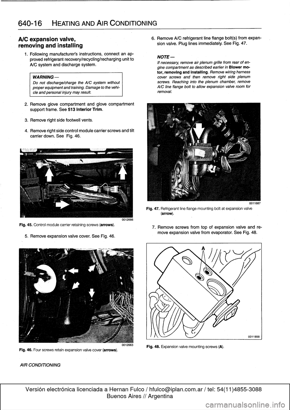
See
Fig
.
46
.
5
.
Remove
expansion
valve
cover
.
See
Fig
.
46
.
Fig
.
46
.
Four
screws
retain
expansion
valve
cover
(arrows)
.
AIR
CONDITIONING
0012666
0012663
6
.
Remove
A/C
refrigerant
line
fiange
bolt(s)
from
expan-
sion
valve
.
Plug
lines
immediately
.
See
Fig
.
47
.
NOTE
-
If
necessary,
remove
air
plenum
grille
fromrear
of
en-
gine
compartment
as
described
earlier
in
Blower
mo-
tor,
removing
and
installing
.
Remove
wiring
hamess
cover
screws
and
then
remove
right
side
plenum
screws
.
Reaching
finto
the
plenum
chamber,
remove
AIC
fine
flange
bolt
to
allow
expansion
valve
room
for
removal
.
Fig
.
47
.
Refrigerant
line
fiange
mounting
boltat
expansion
valve(arrow)
.
7
.
Remove
screws
from
top
of
expansion
valve
and
re-
move
expansion
valve
from
evaporator
.
See
Fig
.
48
.
Fig
.
48
.
Expansion
valve
mountingscrews
(A)
.
0011667
Page 469 of 759
Rear
speaker,
removing
and
installing
Door
panel
speaker,
removing
and
installing
NOTE
-
Rear
speakers
in
convertible
models
are
installed
un-
der
the
rear
side
panels
.
For
rearside
panelremoval
procedure,
see
411Doors
.
1
.
Working
at
rear
parcel
shelf,
pry
speakercoverby
inner
edge
and
remove
.
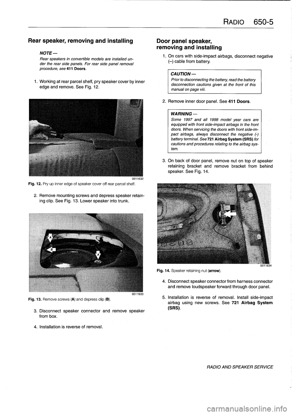
See
Fig
.
12
.
0011632
Fig
.
12
.
Pry
up
inner
edge
of
speaker
cover
off
rear
parcel
shelf
.
2
.
Remove
mountingscrews
and
depress
speaker
retain-
ing
clip
.
See
Fig
.
13
.
Lower
speaker
into
trunk
.
Fig
.
13
.
Remove
screws
(A)
and
depress
clip
(B)
.
4
.
Installation
is
reverse
of
removal
.
0011633
3
.
Disconnect
speaker
connector
andremove
speaker
from
box
.
RAM
650-5
1.
On
carswith
side-impact
airbags,
disconnect
negative
(-)
cable
from
battery
.
CAUTION-
Prior
to
disconnecttog
the
battery,
read
the
battery
disconnection
cautions
given
at
the
front
of
this
manual
on
page
vi¡¡
.
2
.
Remove
inner
door
panel
.
See
411
Doors
.
WARNING
-
Some
1997
and
all
1998
model
year
cars
are
equipped
with
front
side-impact
airbags
in
the
front
doors
.
When
servicing
the
doors
with
front
side-im-
pact
airbags,
alwaysdisconnect
the
negative
()
battery
terminal
.
See
721Airbag
System
(SRS)
for
cautions
and
procedures
relating
to
theairbag
sys-
tem
.
3
.
On
back
of
door
panel,
remove
nut
on
top
of
speaker
retaining
bracket
and
remove
bracket
from
behind
speaker
.
See
Fig
.
14
.
Fig
.
14
.
Speaker
retaining
nut
(arrow)
.
4
.
Disconnect
speaker
connector
from
harness
connector
and
remove
loudspeaker
forwardthrough
door
panel
.
5
.
Installation
is
reverse
of
removal
.
Install
side-impact
airbag
using
new
screws
.
See
721
Airbag
System
(SRS)
.
RADIO
AND
SPEAKER
SERVICE
Page 472 of 759
720-2
SEAT
BELTS
WARNING
-
"
For
maximum
protection
from
injury,
seat
belts
should
be
replaced
as
a
set
(including
all
hard-
ware),
if
they
are
subject
to
occupant
loading
in
a
collision
.
"
Seat
belts
should
not
be
modified
or
repaired
.
The
seat
belt
anchorage
points
should
not
be
changed
or
modified
.
"
Do
notbleach
or
dye
seat
belt
webbing
.
Webbing
that
is
severely
fadedor
re-dyed
will
not
meet
the
strength
requirements
of
a
collision
and
must
be
replaced
.
"
Seat
belts
shouldbe
periodically
inspected
for
webbing
defects
suchas
cuts
or
pulled
threads
.
FRONT
SEATBELT
ASSEMBLY
Automatic
Front
Seat
Belt
Lock
Tensioners
The
procedure
for
disabling
the
mechanical
spring
tension-
er
used
on
early
cars
is
covered
below
.
On
cars
with
thepyro-
technic(explosive
device)
tensioners,
the
orange
harness
connectorshould
be
removed
from
the
tensioner
any
time
the
seat
is
removed
.
WARNING
-
Both
the
mechanical
and
the
pyrotechnictensioners
are
powerful
devíces
and
shouldbehandled
with
extreme
care
.
Mechanical
spring
tensioner,
disarming
1
.
Remove
front
seat
.
See
520
Seats
.
2
.
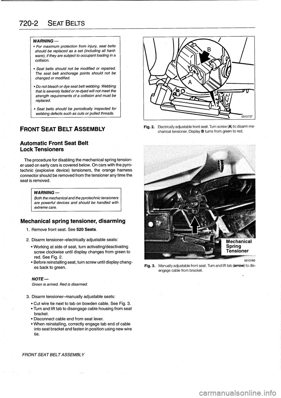
Disarm
tensioner-electrically
adjustableseats
:
"
Working
at
side
of
seat,
turn
activating/deactivating
screw
clockwise
until
display
changes
from
green
to
red
.
See
Fig
.
2
.
"
Before
reinstalling
seat,
turn
screw
until
display
chang-
esback
to
green
.
NOTE-
Green
is
armed
.
Red
is
disarmed
.
3
.
Disarm
tensioner-manually
adjustable
seats
:
"
Cut
wíre
tie
next
to
tab
on
bowden
cable
.
See
Fig
.
3
.
"
Turn
and
lift
tabto
disengage
cable
housing
from
seat
bracket
.
"
Disconnect
cable
end
from
seat
lever
.
"
When
reinstalling,
correctly
engage
tab
end
of
cable
into
seat
bracket
and
fasten
in
position
using
new
wíre
tie
.
FRONT
SEATBELT
ASSEMBLY
0012737
Fig
.
2
.
Electrically
adjustable
front
seat
.
Turn
screw
(A)
to
disarm
me-
chanical
tensioner
.
Display
B
tucos
from
green
to
red
.
F19
.3
.
Manuallyadjustablefrontseat
.Turnandlifttab(arrow)todis-
Page 474 of 759
720-
4
SEAT
BELTS
REAR
SEAT
BELT
ASSEMBLY
On
4-door
E36
models,
there
are
two
3-point
shoulder
belts
and
a
center
lap
beltin
back
.
On
2-doormodels,
there
is
no
center
rear
lap-belt
.
In
models
with
the
stationary
rear
seat
back,
the
shoulder
belt
reels
are
bolted
to
themiddle
of
the
parcel
shelf
.
In
modeis
with
fold-down
rearseat
back,
the
shoulder
belt
reels
are
at-
tached
to
the
folding
seat
back
.
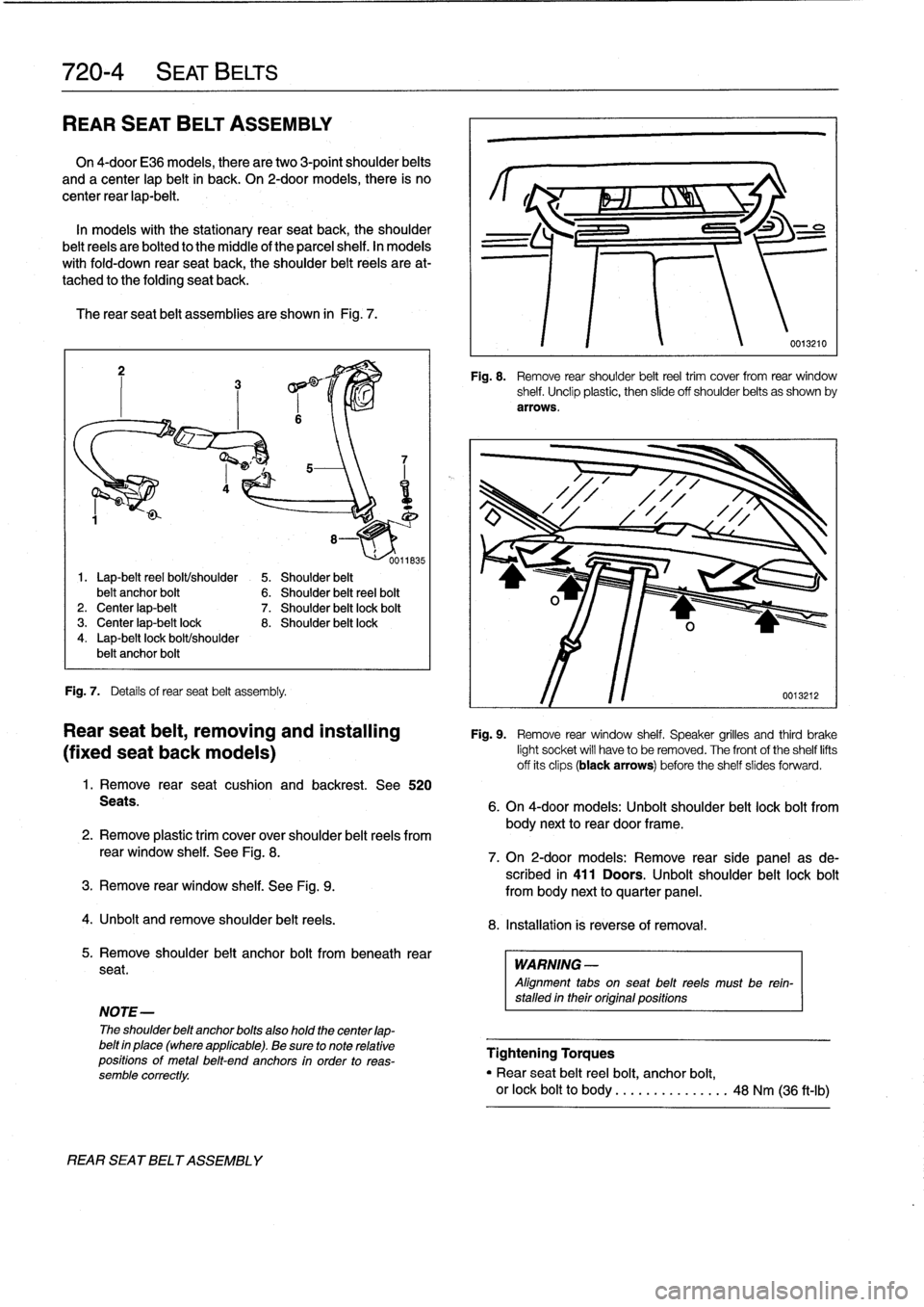
The
rearseat
belt
assemblies
are
shown
in
Fig
.
7
.
Fig
.
7
.
Detafs
of
rearseat
belt
assembly
.
Seats
.
REAR
SEA
T
BELT
ASSEMBLY
1
.
Remove
rear
seat
cushion
and
backrest
.
See
520
2
.
Remove
plastictrim
cover
over
shoulder
belt
reels
from
rear
window
shelf
.
See
Fig
.
8
.
3
.
Remove
rear
window
shelf
.
See
Fig
.
9
.
4
.
Unbolt
andremove
shoulder
belt
reels
.
NOTE-
The
shoulder
belt
anchor
belts
also
hold
thecenter
lap-
belt
in
place(where
applicable)
.
Be
sure
to
note
relative
positions
of
metal
belt-end
anchors
in
order
to
reas-
semble
correctly
.
body
next
to
rear
door
frame
.
8
.
Installation
is
reverse
of
removal
.
5
.
Remove
shoulder
belt
anchor
bolt
frombeneath
rear
seat
.
WARNING
-
Alignment
tabs
on
seat
belt
reels
must
be
rein-
stalled
in
their
original
positions
Fig
.
8
.
Remove
rear
shoulder
belt
reel
trim
cover
from
rear
window
shelf
.
Unclip
plastic,
then
slide
off
shoulder
belts
as
shown
by
arrows
.
Rear
seat
belt,
removing
and
installing
Fig
.
9
.
Remove
rear
window
shelf
.
Speaker
grilles
and
third
brake
(fixed
seat
back
modeis)
light
socket
will
have
to
be
removed
.
The
front
of
the
shelf
lifts
offits
clips
(black
arrows)
before
the
shelf
slides
forward
.
6
.
On
4-door
models
:
Unbolt
shoulder
belt
lock
bolt
from
7
.
On
2-door
models
:
Remove
rearside
panel
asde-
scribed
in
411
Doors
.
Unbolt
shoulder
belt
lock
bolt
from
body
nextto
quarter
panel
.
Tightening
Torques
"
Rear
seat
belt
reelbolt,
anchor
bolt,
or
lock
boltto
body
.
.
.....
.
...
...
.
48
Nm
(36
ft-Ib)
Page 475 of 759
Rear
seat
belt,
removing
and
installing
(foid-down
seat
back
modeis)
1
.
Remove
rear
seat
cushion
.
See
520
Seats
.
2
.
Remove
shoulder
belt
anchor
bolt
from
beneath
rear
seat
.
NOTE
-
The
shoulder
belt
anchor
bolts
alsohold
the
center
lap-belt
in
place
(where
applicable)
.
Be
sure
to
note
relative
positions
of
metal
belt-end
anchors
in
order
to
reas-
semble
correctly
.
3
.
On
4-door
models
:
Unbolt
shoulder
belt
lock
bolt
from
body
nextto
rear
door
frame
.
4
.
On
2-door
models
:
Remove
rearside
panel
as
de-
scribed
in
411
Doors
.
Unbolt
shoulder
belt
lock
bolt
from
body
next
to
quarter
panel
.
5
.
Unlock
and
flip
down
folding
rear
seat
backrest
.
Re-
move
trim
plug
from
back
of
cushion
(luggage
compart-
ment
side)
.
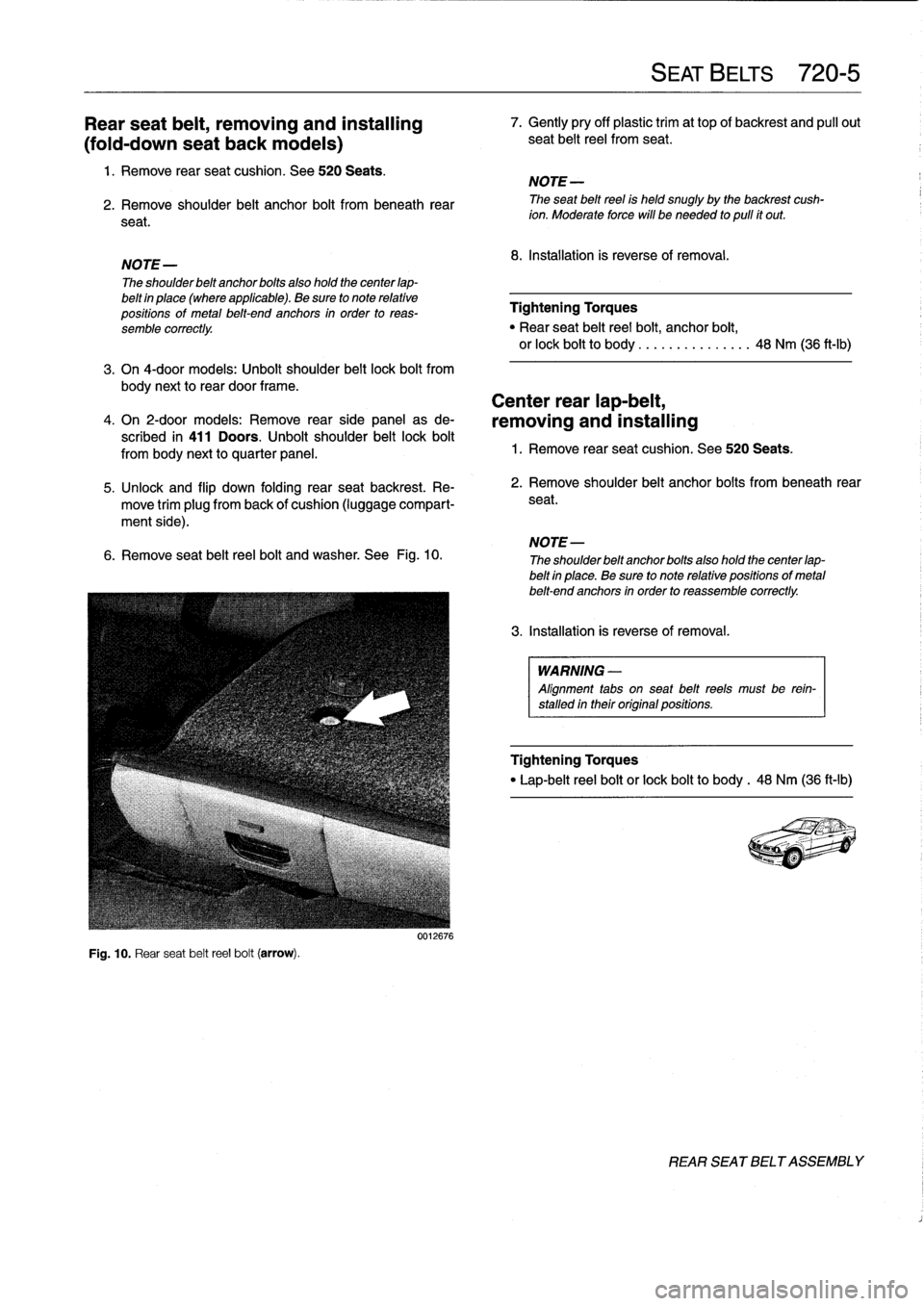
6
.
Remove
seat
beltreelbolt
andwasher
.
See
Fig
.
10
.
Fig
.
10
.
Rear
seat
beltreelbolt
(arrow)
.
0012676
7
.
Gently
pry
off
plastic
trim
at
top
of
backrest
and
pull
out
seat
beltreel
from
seat
.
NOTE-
The
seat
beltreel
is
held
snugly
by
the
backrest
cush-
ion
.
Moderate
force
will
be
needed
to
pulí
ít
out
.
8
.
Installation
is
reverse
of
removal
.
Tightening
Torques
"
Rear
seat
beltreel
bolt,
anchor
bolt,
or
lock
boltto
body
...............
48
Nm
(36
ft-Ib)
Center
rear
lap-belt,
removing
and
installing
1
.
Remove
rear
seat
cushion
.
See520
Seats
.
2
.
Remove
shoulder
belt
anchor
bolts
from
beneath
rear
seat
.
3
.
Installation
is
reverse
of
removal
.
SEAT
BELTS
720-
5
NOTE-
The
shoulderbeltanchorbolts
also
hold
the
centerlap-
belt
in
place
.
Be
sure
to
note
relative
positions
of
metal
belt-end
anchors
in
order
to
reassemble
correctly
.
WARNING
-
Alignment
tabs
on
seat
belt
reels
must
be
rein-
stalled
in
their
original
positions
.
Tightening
Torques
"
Lap-belt
reelbolt
or
lock
boltto
body
.
48
Nm
(36
ft-Ib)
REAR
SEATBELT
ASSEMBLY
Page 477 of 759
721
Airbag
System
(SRS)
Airbag
Systems
.......
.
...
.
.
.
.
.
....
.
.
.
.
721-1
AIRBAG
SENSORS
AND
ELECTRONICS
721-2
SRS
Warning
Light
and
Fault
Display
.
.
.
.
.
..
721-2
Airbagcontact
ring,
replacing
........
.
.
.
.
.
721-3
Airbag
crash
sensor,replacing
..
.
....
.
...
.
721-4
ZAE
control
module,
replacing
.
.
.
.........
721-5
GENERAL
This
repair
group
covers
only
removal
and
installation
of
air-
bag
components
.
Airbag
system
repair
and
fault
diagnosis
is
not
covered
here
.
Diagnostics,
component
testing,
and
airbag
system
repair
should
be
carried
out
by
trained
BMW
service
technicians
.
NOTE-
Special
test
equipment
is
required
to
retrieve
SRS
fault
codes,
diagnose
system
faults,
and
resetltum
off
the
SRS
indicator
light
.
The
SRS
indicator
light
will
remain
on
until
any
problem
has
been
corrected
and
the
fault
memory
has
been
cleared
.
When
servicing
cars
equipped
with
SRS,
the
precautions
on
this
page
mustbeobserved
to
prevent
personal
injury
.
Airbag
Systems
The
airbag
system
installed
on
E36
cars
through
the
1993
model
year
consisted
of
a
single
airbag
in
the
steering
wheel
.
This
systemcan
be
identified
by
the
orange
crash
sensors
lo-
cated
on
the
front
wheel
wells
and
the
absence
of
a
passenger
side
airbag
.
The
ZAE
airbag
system,
starting
in
model
year
1994
(pro-
duction
date9/93
and
later),
provides
both
a
driver
side
and
a
passenger
sideairbag
.
On
ZAE
vehicles,
the
crash
sensorsare
integrated
into
the
airbag
control
module,
located
under
thecenter
of
the
rear
seat
.
The
ZAE
control
module
triggers
deployment
of
the
airbags
When
it
sensos
the
vehicle
deceler-
ating
at
a
rate
equivalent
to
a
head-on
collisionof
at
least
13
mph
(18
km/h)
.
In
some
1997
4-door
models
and
all
1998
models,
side-impact
airbags
were
installed
in
the
front
doors
.
The
airbag
units
are
mounted
behindthe
door
trim
panels
.
Caution
mustbeused
when
working
on
vehicle
systems
in
the
proximity
of
air
bags,
such
as
the
steering
column,
the
dashboard,
or
the
doors
.
AIRBAG
SYSTEM
(SRS)
721-1
GENERAL
.
.
.
.
.
.
.
.
.
.
.......
.
......
.
.
.
.
721-1
Front
side-impact
airbag
crash
sensor,
removing
and
installing
....
.
.....
.
.....
.
721-5
AIRBAGS
..............
.
.
.
.
.
.
.
.
.
.
.
.
.
.
.
721-5
Driver
side
airbag,
removing
and
installing
.
.
.
721-5
Passenger
side
airbag,
removing
and
installing
..............
.
.
.721-6
Front
side-impact
airbag,
removing
and
installing
.
.
.
.
.
.
.
.
.
.
......
.721-7
WARNING
-
"
Airbag(s)
are
inflated
byan
explosive
device
.
Handled
improperly
or
without
adequate
safe-
guards,
the
System
can
be
very
dangerous
.
Spe-
cial
precautions
must
be
observed
prior
to
any
work
ator
near
the
driverside
airbag,
the
passen-
ger
side
airbag
(where
applicable)
or
the
side-im-
pact
airbags
(where
applicable)
.
"
The
airbag
is
a
vehicle
safety
system
.
Serious
in-
jury
may
result
if
System
service
is
attempted
by
persons
unfamiliar
with
the
BMW
SRS
and
its
ap-
proved
service
procedures
.
BMW
advises
that
all
inspection
and
service
be
performed
by
an
autho-
rized
BMW
dealer
.
"
Always
disconnect
the
battery
and
cover
the
neg-
ative
()
battery
terminal
with
an
insulator
before
startingdiagnostic,
troubleshooting
or
service
worknot
associated
with
SRS,
and
before
doing
any
welding
on
the
car
.
"
If
an
airbag
has
been
activated
due
to
an
acci-dent,
BMW
specifies
that
SRS
components
be
replaced
.
For
more
information
on
post-collision
SRS
service,
see
an
authorized
BMW
dealer
.
"
Do
not
allow
the
airbag
unit
to
come
in
contact
with
cleaning
solutions
orgrease
.
Never
subject
an
airbag
unit
to
temperatures
aboye
212°F
(100°C)
.
When
reconnecting
the
battery,
no
per-
son
should
be
inside
the
vehicle
.
"
Always
place
an
airbag
unitthat
has
been
re-
moved
from
its
packaging
with
the
padded
sidefacing
upward
.
Do
not
leave
an
airbag
unlt
unat-
tended
.
"
!f
the
airbag
unit
or
airbag
control
modulehas
been
dropped
froma
height
of
!
1
2
meter
(1
Y2
ft.)
ormore,
theairbag
unit
should
not
be
installed
.
Aírbag
system
components
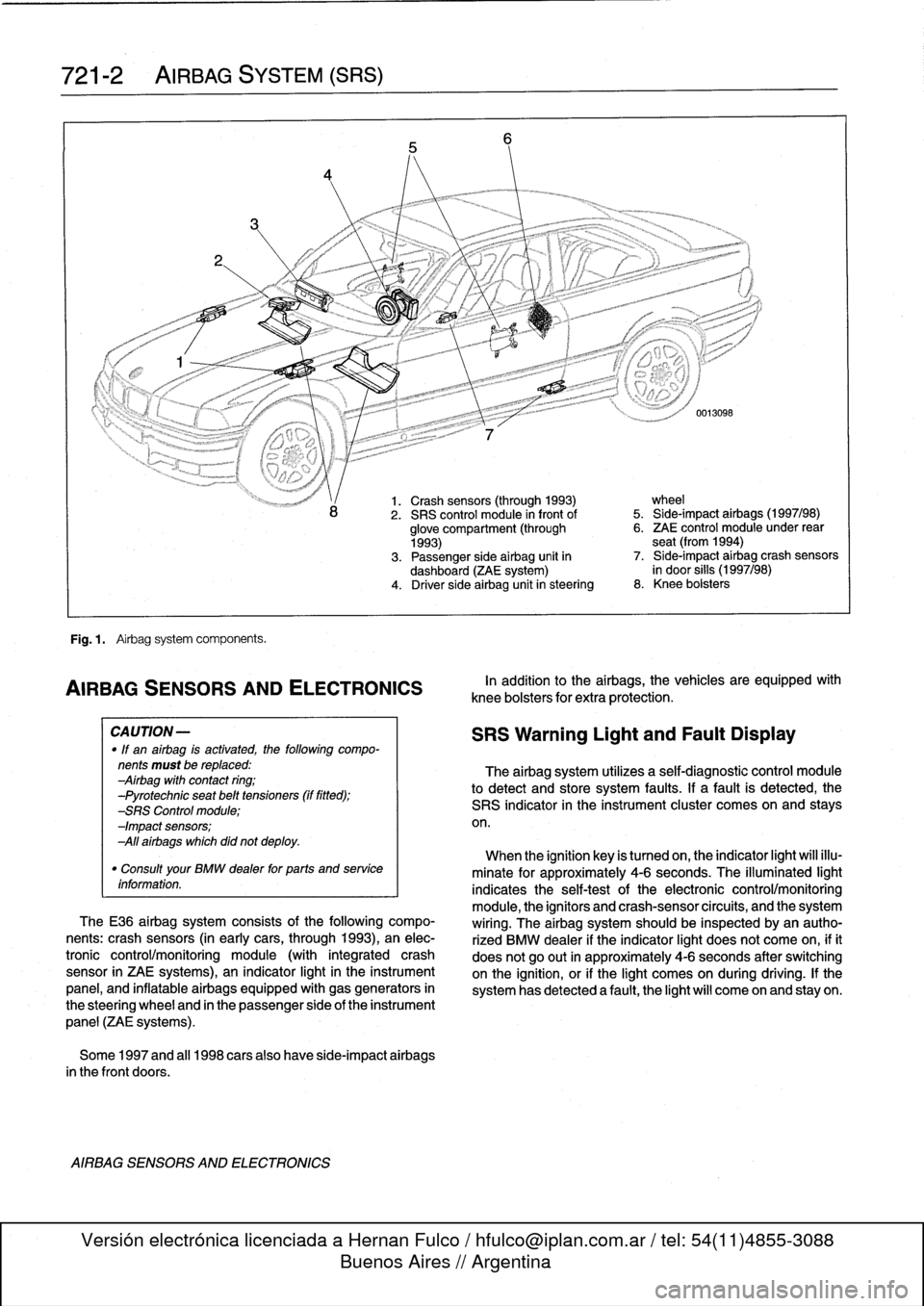
are
shown
in
Fig
.
1.
GENERAL
Page 478 of 759
721-2
AIRBAG
SYSTEM
(SRS)
Fig
.
1
.
Airbag
system
components
.
AIRBAG
SENSORSAND
ELECTRONICS
CA
UTION-
"
If
an
airbag
is
activated,
the
following
compo-
nents
must
be
replaced
:
Airbag
with
contact
ring
;
-Pyrotechnic
seat
belt
tensioners
(if
fitted)
;
-SRS
Control
module
;
-Impact
sensors
;
All
airbags
which
did
not
deploy
.
"
Consult
your
BMW
dealer
for
parts
and
service
information
.
TheE36
airbag
system
consists
of
the
following
compo-
nents
:
crash
sensors
(in
earlycars,
through
1993),
an
elec-
tronic
control/monitoring
module
(with
integrated
crash
sensor
in
ZAE
systems),
an
indicator
light
in
the
instrument
panel,
and
inflatable
airbags
equipped
with
gas
generators
in
the
steering
wheel
and
in
the
passenger
side
of
the
instrument
panel
(ZAE
systems)
.
Some
1997
and
al¡
1998
carsalso
have
side-impact
airbags
in
the
front
doors
.
AIRBAG
SENSORS
AND
ELECTRONICS
1.
Crash
sensors
(through
1993)
wheel
2
.
SRS
control
module
in
front
of
5
.
Side-impact
airbags
(1997/98)
glove
compartment
(through
6
.
ZAE
control
module
under
rear
1993)
seat
(from
1994)
3
.
Passenger
side
airbag
unit
in
7
.
Side-impact
airbag
crash
sensors
dashboard
(ZAE
system)
in
door
silis
(1997/98)
4
.
Driver
side
airbag
unitin
steering
8
.
Knee
bolsters
In
addition
to
the
airbags,
the
vehicles
are
equipped
wíth
knee
bolsters
for
extra
protection
.
SRS
Warning
Light
and
Fault
Display
The
airbag
system
utilizes
a
self-diagnostic
control
module
to
detect
and
store
system
faults
.
If
a
fault
is
detected,
the
SRS
indicator
in
the
instrument
cluster
comes
on
and
stays
on
.
When
the
ignition
key
is
tumed
on,
the
indicator
light
will
illu-
minate
for
approximately
4-6
seconds
.
The
illuminated
light
indicates
the
self-testof
the
electronic
control/monitoring
module,
the
ignítors
and
crash-sensorcircuits,
and
the
system
wiring
.
The
airbag
system
should
be
inspected
byan
autho-
rized
BMW
dealer
if
the
indicator
light
does
not
come
on,
ifit
does
not
go
out
in
approximately
4-6
seconds
after
switching
onthe
ignition,
or
if
the
light
comes
on
during
driving
.
If
the
system
has
detected
a
fault,
the
light
will
come
on
and
stay
on
.
Page 479 of 759
1
.
Disconnect
negative
(-)
cable
from
battery
and
cover
negative
terminal
with
insulating
material
.
CA
UTION-
Prior
to
disconnectiog
the
battery,
read
the
battery
disconnection
cautions
given
at
the
front
of
this
manual
on
page
viii
.
2
.
Remove
driver
sideairbag
from
steering
wheel
.
See
Driver
side
airbag,
removing
and
installing
in
this
repair
group
.
3
.
With
wheels
facing
straight
ahead
and
steering
wheel
centered,
remove
steering
wheel
.
See320
Steering
and
Wheel
Alignment
.
4
.
Remove
contact
ring
cover
(flat
plastic
ring
containing
warning
text)
from
steering
wheel,
íf
applicable
.
5
.
Disconnect
ground
wire,
if
applicable
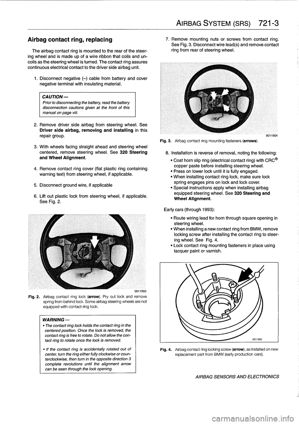
6
.
Lift
out
plastic
lock
from
steering
wheel,
if
applicable
.
See
Fig
.
2
.
0011903
Fig
.
2
.
Airbag
contact
ring
lock(arrow)
.
Pry
out
lock
and
remove
spríng
from
behind
lock
.
Some
airbag
steering
wheels
are
not
equipped
with
contact
ring
lock
.
WARNING
-
"
The
contact
ring
lock
holds
the
contact
ring
in
the
centered
position
.
Once
the
lock
is
removed,
the
contact
ring
is
free
to
rotate
.
Do
not
allow
the
con-
tact
ring
to
rotate
once
the
lock
is
removed
.
"
If
the
contact
ring
is
accidentally
rotated
outof
center,
turn
the
ring
either
fully
clockwise
orcoun-
terclockwise,
then
turn
in
the
opposite
direction
3
complete
revolutions
until
the
alignment
arrow
canbe
seen
through
the
lock
opening
.
AIRBAG
SYSTEM
(SRS)
721-
3
Airbagcontact
ring,
replacing
7
.
Remove
mounting
nutsor
screws
from
contact
ring
.
See
Fig
.
3
.
Disconnect
wire
lead(s)
andremove
contact
The
airbag
contact
ring
is
mounted
to
the
rear
of
the
steer-
ring
from
rear
of
steering
wheel
.
ing
wheel
and
is
made
up
of
a
wireribbon
that
cofs
and
un-
coils
as
the
steering
wheel
is
tumed
.
The
contact
ring
assures
continuous
electrical
contact
to
the
driver
side
airbag
unit
.
Fig
.
3
.
Airbag
contact
ring
mounting
fasteners(arrows)
.
8
.
Installation
is
reverse
ofremoval,noting
the
following
:
"
Coat
horn
slip
ring
(electrical
contact
ring)
with
CRC
®
copper
paste
before
installing
steering
wheel
.
"
Press
on
lower
lock
until
it
ís
fully
engaged
.
"
When
installing
contact
ringlock,
make
sure
lock
spring
engages
pins
on
lock
and
lock
cover
.
"
Special
instructions
apply
when
installing
airbag
equipped
steering
wheel
.
See320
Steering
and
Wheel
Alignment
.
Early
cars
(through
1993)
:
"
Route
wiring
lead
for
horn
through
squareopening
in
steering
wheel
.
"
When
installing
a
new
contact
ring
from
BMW,
remove
locking
screw
after
installing
the
contact
ringto
steer-
ing
wheel
.
See
Fig
.
4
.
"
Lock
contact
ring
mounting
fasteners
in
place
using
lacquer
paint
or
varnish
.
0011904
Fig
.
4
.
Airbag
contact
ring
locking
screw
(arrow),
as
installed
on
new
replacement
part
from
BMW
(early
production
cars)
.
AIRBAG
SENSORS
AND
ELECTRONICS