ECO mode BMW M3 1992 E36 User Guide
[x] Cancel search | Manufacturer: BMW, Model Year: 1992, Model line: M3, Model: BMW M3 1992 E36Pages: 759
Page 115 of 759
119
Lubrication
System
LUBRICATION
SYSTEM
119-1
GENERAL
.
.
.
.
.
.
...
.
.
.
.
.
.
.
...,
,
...
.
.
.
.
119-1
OH
pan,
removing
and
installing
(6-cylinder
engine,
1992
models)
.
.
.
.
.
.
.
.
.
119-4
TROUBLESHOOTING
.
.
.
.
.
.
...
.
.
.
.....
.
119-1
Oil
pan,
removing
and
installing
Oil
pressure,
checking
.
.
.
.
.
.
...
.
.
.
.
.
.
.
.
.
119-1
(6-cylinder
engine,
1993
and
later
models)
.119-6
Oil
pressure
warning
system,
testing
.
.
.
.
.
.
.
119-2
OIL
PUMP
.
.......
.
.............
.119-8
OIL
PAN
.
.
.
.
.
.....
.
.
.
.
.
......
.
.
.
.
.
.
.
..
119-2
Oil
pump,
removing
and
installing
Oil
pan,
removing
and
installing
(4-cylinder
engine)
.
.
.
...
.
..........
.
.
.119-8
(4-cylinder
engines)
.
.
...
.
....
.
.
.
.
.
.
.
..
119-2
Oil
pump,
removing
and
installing
(6-cylinder
engine)
.
.
.....
.
.........
.
.119-10
GENERAL
Oil
pressure,
checking
The
oil
pan
and
the
oil
pump
can
be
removed
with
theen-
gine
installed,
although
engine
liftinglsupport
equipment
is
necessary
.
NOTE-
Oil
change
procedure
and
oil
filter
replacement
are
covered
in
020
Maintenance
Program
.
Al¡
engines
are
equipped
with
an
oil
pressure
warning
sys-
tem
to
help
prevent
engine
damage
.
Other
safety
features
in-
clude
:
"
A
filter
bypass
to
provide
lubrication
should
the
oil
filter
become
clogged
.
"
An
oil
pump
pressure
relief
valve
to
prevent
excessive
system
pressure
.
TROUBLESHOOTING
The
lubrication
warning
system
consists
of
an
oil
pressure
switch
mounted
in
the
oil
circuit
and
an
instrument
panel
warn-
ing
light
.
CAUTION-
If
the
red
oil
pressurewarning
light
comes
on
or
flashes
on
while
driving,
always
assume
that
the
oil
pressure
is
low
.
To
perform
an
oíl
pressure
test,
BMW
specifies
special
tools
that
attach
to
thetop
of
the
oíl
filter
housing
.
The
following
pro-
cedure
works
well
using
standard
automotive
oil
pressure
testing
equipment
attached
to
the
oil
pressure
switch
port
in
the
engine
.
In
some
engines,
however,
access
tothis
port
may
be
extremely
restricted
.
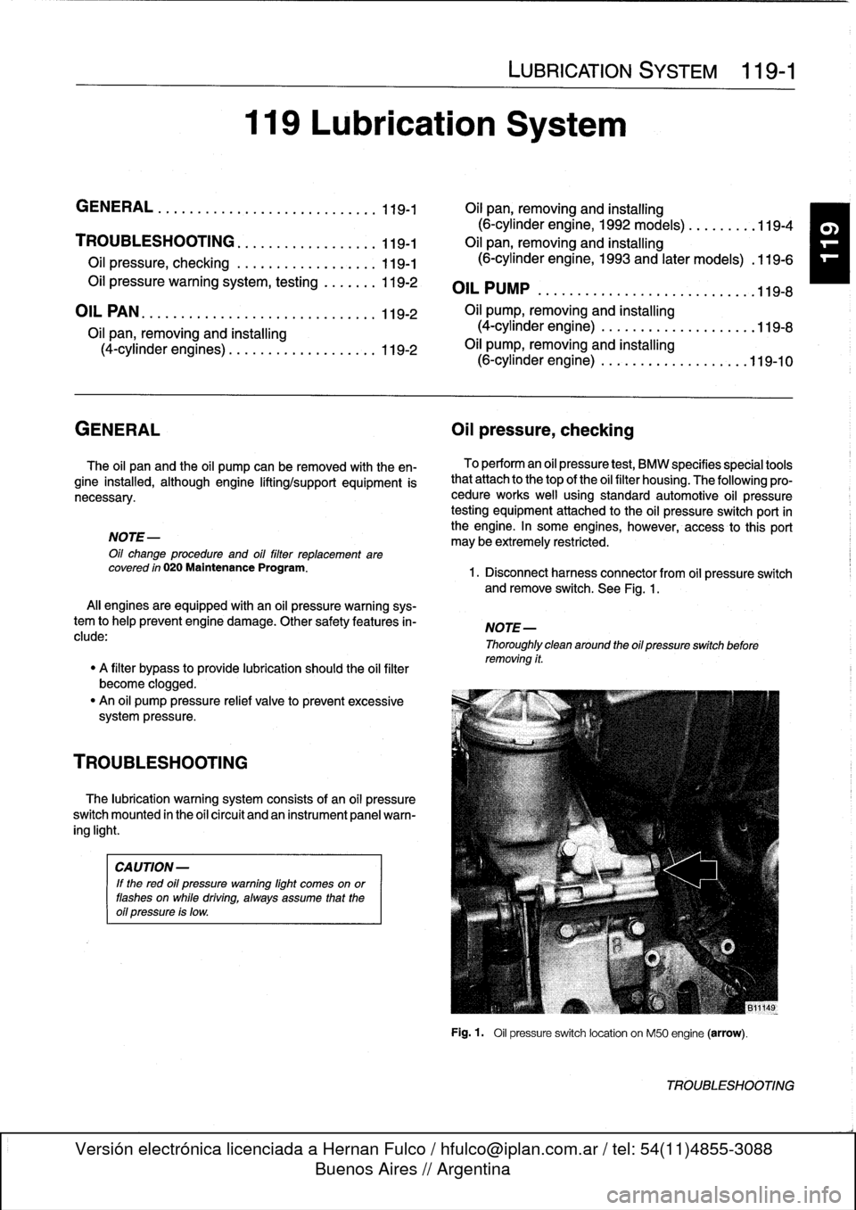
1
.
Disconnect
harness
connector
from
oil
pressure
switch
andremove
switch
.
See
Fig
.
1
.
NOTE-
Thoroughly
clean
around
the
oil
pressure
switchbefore
removing
it
.
Fig
.
1
.
Oil
pressure
switch
location
on
M50
engine
(arrow)
.
TROUBLESHOOTING
Page 120 of 759
119-
6
LUBRICATION
SYSTEM
17
.
Raise
engine
as
much
as
possible
.
Check
carefully
for
22
.
Installation
is
reverse
of
removal
.
obstructions,
wiring
harness
clearance
and
pinched
hoses
or
lines
as
engine
is
raised
.
"
When
installing
oil
pan,
apply
a
b
d
of
non-hardening
sealing
compound
(3-Bond
1209
0
or
equivalent)
to
18
.
Remove
oil
pan
mounting
bolts
and
lower
oil
pan
to
front
and
rear
end
cover
seam
areas
on
block
.
subframe
crossmember
.
"
Position
oil
pump
pickup
tube
and
oil
pan
onto
block
and
install
pickup
tube
using
a
new
gasket
.
"
Be
sure
tab
on
gasket
faces
down
towards
intake
of
NOTE-
pickup
tube
.
If
the
oil
pan
does
not
separate
easily
from
the
engine
"
Tightenforward
oil
pan
screws
first,
then
tighten
rear
.
cylinder
block,
afew
taps
with
arubber
mallet
should
"
Fill
engine
with
oil
as
described
in
020
Maintenance
break
it
free
.
Do
not
pry
the
oil
pan
loose
.
Program
.
"
After
adding
engine
oil,
start
and
run
engine
.
Raise
en-
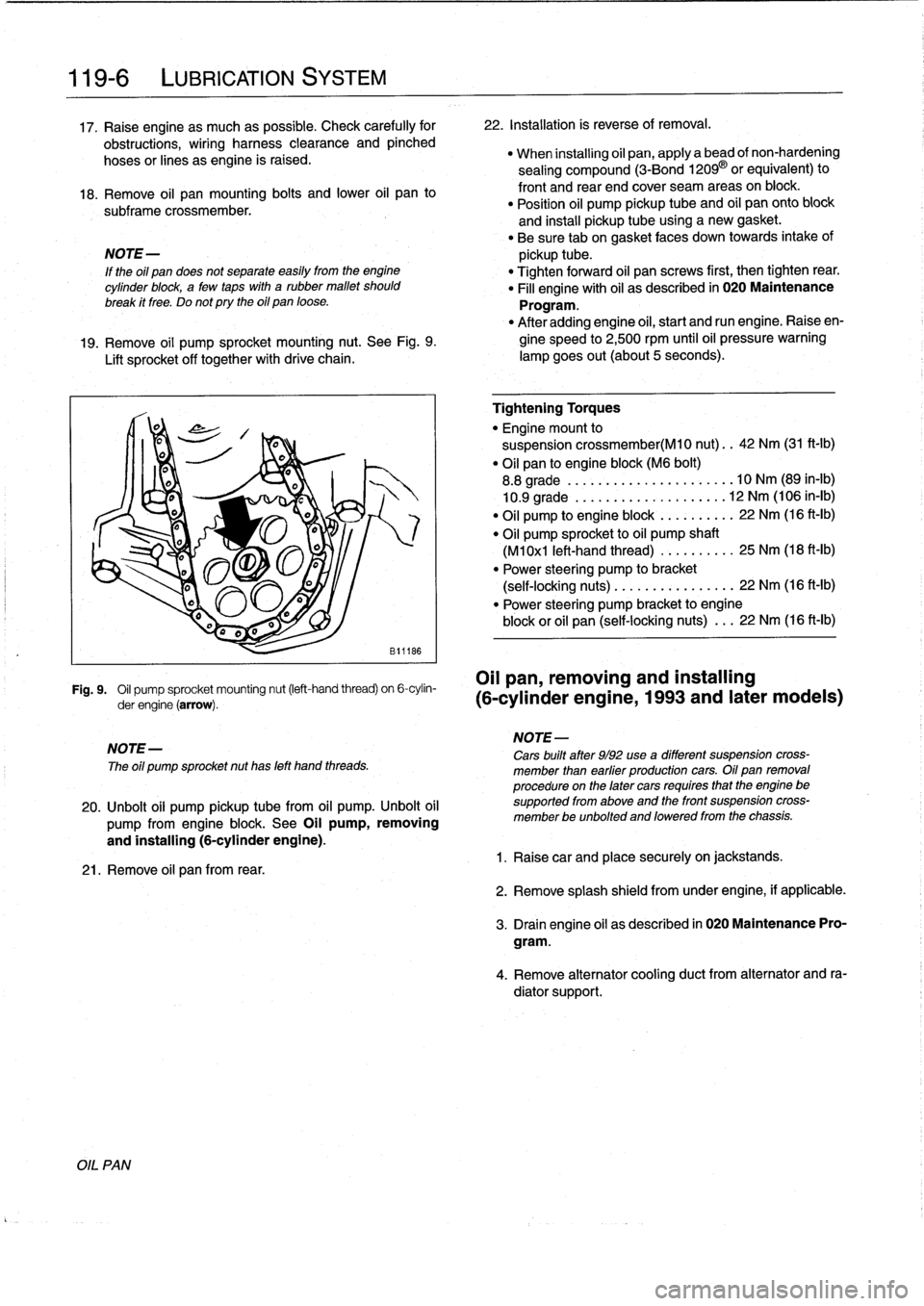
19
.
Remove
oil
pump
sprocket
mounting
nut
.
See
Fig
.
9
.
gine
speed
to
2,500
rpm
until
oil
pressure
warning
Lift
sprocket
off
together
with
drive
chain
.
lampgoes
out(about
5seconds)
.
Fig
.
9
.
Oil
pump
sprocket
mounting
nut
(left-hand
thread)
on
6-cylin-
OII
pan,
removing
and
installing
derengine(arrow)
.
(6-cylinder
engine,
1993
and
later
modeis)
NOTE-
The
oíl
pump
sprocket
nut
has
left
hand
threads
.
20
.
Unbolt
oil
pump
pickup
tubefrom
oil
pump
.
Unbolt
oil
pump
from
engine
block
.
See
Oil
pump,
removing
and
installing
(6-cylinder
engine)
.
21
.
Remove
oil
pan
from
rear
.
Tightening
Torques
"
Engine
mount
to
suspension
crossmember(M10
nut)
..
42
Nm
(31
ft-Ib)
"
Oil
pan
to
engine
block
(M6
bolt)
8
.8
grade
....
..
.
...
...
.
........
10
Nm
(89
in-lb)
10
.9
grade
.
.
..
.
..
...
.
.
.
.
.
.....
12
Nm
(106
in-lb)
"
Oil
pump
to
engine
block
.
...
...
.
..
22
Nm
(16
ft-Ib)
"
Oil
pump
sprocket
to
oil
pump
shaft
(M1
0x1
left-hand
thread)
...
..
.
.
..
.
25
Nm
(18
ft-Ib)
"
Power
steering
pump
to
bracket
(self-locking
nuts)
.....
.
....
..
.
...
22
Nm
(16
ft-lb)
"
Power
steering
pump
bracket
to
engine
block
or
oil
pan
(self-locking
nuts)
.
..
22
Nm
(16
ft-Ib)
NOTE-
Cars
built
after
9/92
use
a
different
suspension
cross-
member
¡han
earfier
productíon
cars
.
Oil
pan
removal
procedure
on
the
later
cars
requíres
that
the
engine
be
supported
from
aboye
and
the
front
suspension
cross-
member
be
unbolted
and
loweredfrom
the
chassis
.
1
.
Raisecar
and
place
securely
on
jackstands
.
2
.
Remove
splash
shield
fromunder
engine,
if
applicable
.
3
.
Drain
engine
oil
as
descríbed
in
020
Maintenance
Pro-
gram
.
4
.
Remove
alternator
cooling
duct
from
alternator
and
ra-
diator
support
.
Page 154 of 759
130-
8
FUEL
INJECTION
Fig
.
8
.
Fuel
pump
relayterminal
identification
.
1.
Peel
back
rubber
boot
on
oxygen
sensor
electrical
har-
ness
connector
(car
wiring
side)
.
With
connector
at-
Oxygen
sensor,
testing
tached
to
sensor,
connect
digital
voltmeter
to
pins
1
(BOSch
systems
only)
and
2
in
rear
of
connector
.
See
Fig
.
10
.
CAUTION-
"
The
information
inthis
sectionapplies
to
Bosch
engine
management
systems
only
.
"
The
Siemens
MS
41
.1
system
uses
resistive-type
oxygen
sensors
.
This
sensor
uses
a
5-volt
refer-
ence
signal
input
and
the
output
to
the
ECM
var-
ees
from
1-5
volts,
in
stepped
increments
based
on
oxygen
content
in
the
exhaust
.
NOTE-
"
On
pre-08D
11(1992-1995)
cars,
there
is
one
oxygen
sensor
mounted
upstream
of
the
catalytic
convert-
er(s)
in
the
exhaust
pipe
.
See
Fig
.
9
.
"
On
OBD
11
cars
(1996-1998)
cars,
there
is
one
oxygen
sensor
before
andone
after
each
catalytic
converter
.
"
OnM52
and
S52US
engines,
the
front
pairof
oxygen
sensors
are
installed
in
the
exhaust
manifolds
.
The
oxygen
sensor
providesan
input
voltage
signal
(0-1
VDC)
to
the
ECM
based
on
the
oxygen
content
in
the
exhaust
gas
.
TO
generate
voltage,
the
sensor
temperature
must
exceed
575°F
(300°C)
.
Therefore
it
ís
electrically
heated
.
NOTE-
"
The
test
given
below
is
not
a
conclusive
test
of
oxygen
sensor
efficiency
and
does
not
test
how
quickly
the
oxygensensor
can
react
to
changing
conditions
.
"
Pin
numbers
and
wirecolors
can
vary
.
Always
check
the
wiring
diagrams
to
conflrm
wire
color
and
pinas-
signment
.
ELECTRICAL
CHECKS
AND
COMPONENT
TESTING
0013135
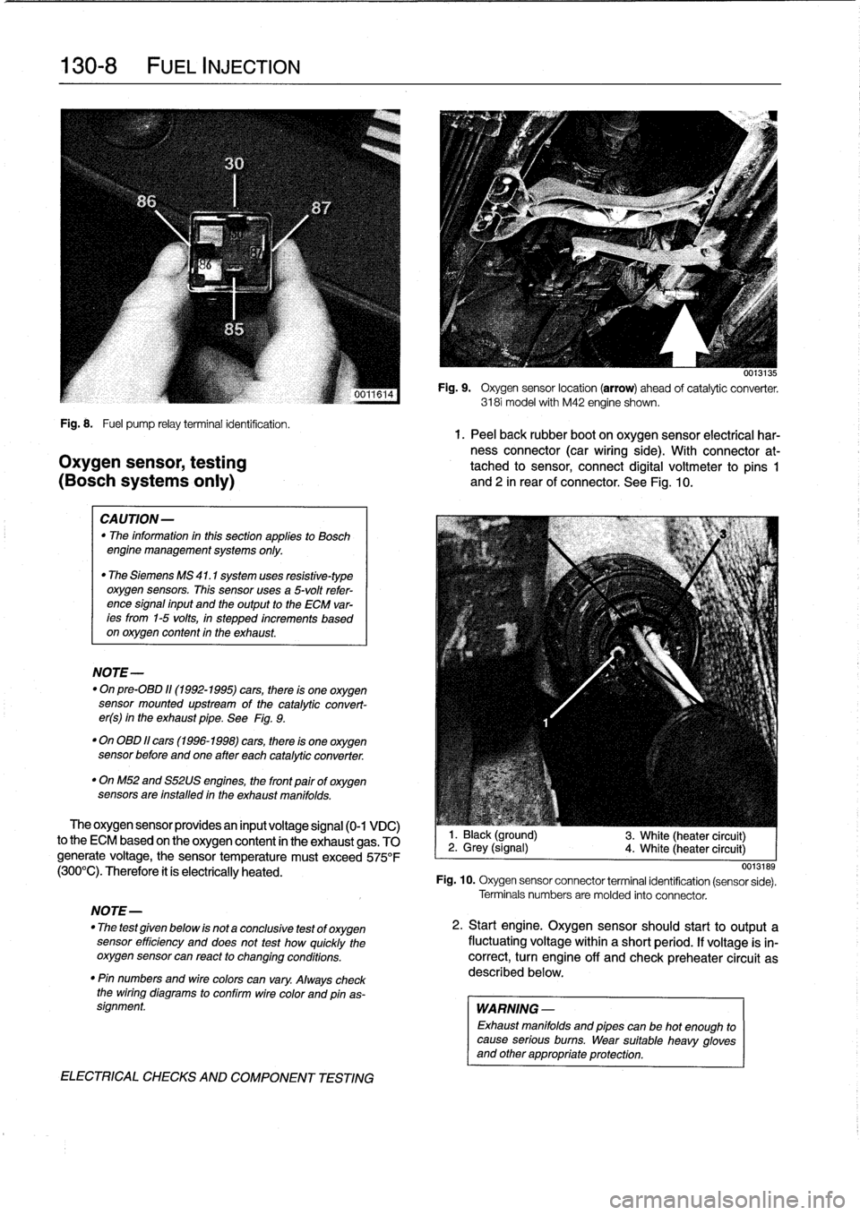
Fig
.
9
.
Oxygen
sensor
location
(arrow)
ahead
of
catalytic
converter
.
3181
model
with
M42
engine
shown
.
1
.
Black
(ground)
2
.
Grey
(signal)
4
.
White
(heater
circuit)
3
.
White
(heater
circuit)
0013189
Fig
.
10
.
Oxygen
sensor
connector
terminal
identification
(sensor
sede)
.
Terminals
numbers
are
molded
into
connector
.
2
.
Start
engine
.
Oxygen
sensorshould
start
to
output
a
fluctuating
voltage
within
a
short
period
.
If
voltage
is
in-
correct,
turn
engine
off
and
check
preheater
circuit
as
described
below
.
WARNING
-
Exhaust
manifolds
and
pipes
can
be
hot
enough
to
cause
serious
burns
.
Wear
suitable
heavy
gloves
and
other
appropriate
protection
.
Page 163 of 759
BOSCH
DME
MM
AND
M33
.1
COMPONENT
TESTS
AND
REPAIRS
Consult
Table
a
for
engine
application
information
for
the
Bosch
DME
3
.1
and
3
.3.1
systems
.
The
DME
3
.1
and
DME
3
.3
.1
systems
are
similar
in
opera-
tion,
with
knock
control
and
VANOS
operation
being
the
key
differences
.
DME
3
.1
engines
arenot
equipped
with
VANOS
or
knock
detectors,
while
the
DM
E3
.3
.1
system
is
.
CA
UTION-
Use
onty
a
digital
multimeter
when
testing
wiring
.
Use
of
an
analog
VOM
may
damage
the
engine
control
module
.
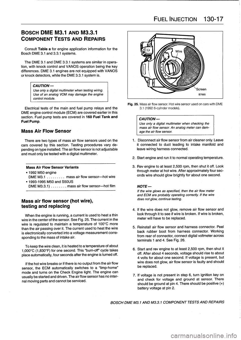
Fig
.
25
.
Mass
air
flow
sensor
.
Hot
wire
sensor
usedon
carswith
DME
Electrical
tests
of
the
main
and
fuel
pump
relays
and
the
3
.1
(1992
6-cylinder
models)
.
DME
engine
control
module
(ECM)
are
covered
earlier
in
this
section
.
Fuel
pump
tests
are
covered
in
160
Fuel
Tank
and
CAUTION-
Fuel
Pump
.
Use
only
a
digital
multimeter
when
checking
the
mass
air
flow
sensor
.
An
analog
meter
can
dam-
Mass
Air
Flow
Sensor
age
theair
flow
sensor
.
There
are
two
types
of
mass
air
flow
sensors
used
onthe
1
.
Disconnect
air
flow
sensor
from
air
cleaner
only
.
Leave
cars
covered
by
this
section
.
Testing
procedures
vary
de-
it
connected
to
duct
leading
to
intake
manifold
and
pending
on
type
installed
.
The
airflow
sensor
is
not
adjustable
leave
wiring
harness
connected
.
and
must
only
be
tested
with
a
digital
multimeter
.
Mass
Air
FlowSensor
Variants
"
1992
M50
engine
DME
M3
.1
.
.
.
.
...
..
mass
air
flow
sensor-hot
wire
"
1993-1995
M50
and
S50US
DMEM33
.1)
.
...
...
.
mass
air
flow
sensor-hot
film
Mass
air
flow
sensor
(hot
wire),
testing
and
replacing
When
the
engine
is
running,
a
current
is
used
to
heat
a
thin
wire
in
the
center
of
the
sensor
.
See
Fig
.
25
.
The
current
in
the
wire
is
regulated
to
maintain
a
temperature
of
100°C
more
than
the
air
passing
over
it
.
The
current
used
to
heat
the
wire
is
electronically
conneced
into
a
voltage
measurement
corre-
sponding
to
the
mass
of
intake
a¡
r
.
To
keep
the
wire
clean,
it
is
heated
to
a
temperature
of
about
1,000°C
(1,830°F)
for
one
second
.
This
"burn-off"
cycle
takes
place
automatically,
four
seconds
after
the
engine
is
tumed
off
.
lf
thehot
wire
breaks
or
if
there
is
no
output
from
the
air
flow
sensor,
the
ECM
automatically
switches
to
a
"limp-home"
mode
and
tucos
on
the
Check
Engine
light
.
The
engine
can
usually
be
started
and
driven
.
The
air
flow
sensor
has
no
inter-
nal
moving
parts
and
cannot
be
serviced
.
FUEL
INJECTION
130-
1
7
2
.
Start
engine
and
run
it
to
normal
operating
temperature
.
3
.
Rev
engine
toat
least
2,500
rpm,then
shut
it
off
.
Look
through
meter
at
hot
wire
.
After
approximately
four
sec-
onds
wire
should
glow
brightly
for
about
one
second
.
NOTE
-
If
the
wire
glowsas
specified,
then
the
airflow
meter
and
ECM
are
probably
operating
correctly
.
lf
the
wire
does
not
glow,
continue
testing
.
4
.
lf
the
wire
does
not
glow,
remove
air
flow
sensor
and
look
through
it
to
see
if
wire
is
broken
.
lf
wire
is
broken,
meter
will
have
to
be
replaced
.
5
.
Reinstall
air
flow
sensor
and
harness
connector
.
Peel
back
rubber
bootfrom
harness
connector
.
Working
from
rear
of
connector,
connect
digital
voltmeter
across
terminals
1
and
4
.
See
Fig
.
26
.
6
.
Start
and
rev
engine
toat
least
2,500
rpm,thenshut
it
off
.
After
about
4
seconds,
voltage
should
riseto
about
4
volts
for
about
one
second
.
lf
voltage
is
present,
but
wire
does
not
glow,
air
flow
sensor
is
faulty
and
should
be
replaced
.
7
.
lf
voltage
is
not
present
in
step
6,
turn
ignition
key
on
and
check
for
voltage
and
ground
at
sensor
.
There
should
beground
at
pin
4
.
There
should
be
positive
(+)
battery
voltage
at
pin
2
.
BOSCH
DME
M3
.1
AND
M32
.1
COMPONENT
TESTS
AND
REPAIRS
Page 196 of 759
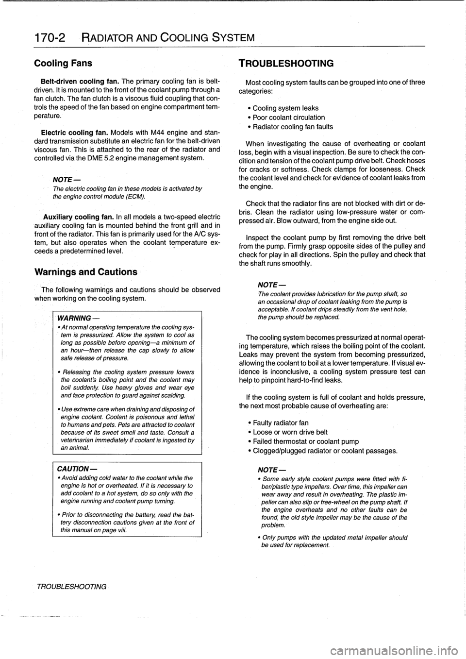
170-2
RADIATOR
AND
COOLING
SYSTEM
Cooling
Fans
TROUBLESHOOTING
Belt-driven
coolingfan
.
The
primary
cooling
fan
is
belt-
driven
.
It
is
mounted
to
the
frontof
the
coolant
pump
through
a
fan
clutch
.
The
fan
clutch
is
a
viscous
fluid
coupling
that
con-
trols
the
speed
of
thefan
based
on
engine
compartment
tem-
perature
.
Electric
cooling
fan
.
Models
with
M44
engine
and
stan-
dard
transmission
substitute
an
electric
fan
for
the
belt-driven
viscous
fan
.
This
is
attached
to
the
rear
of
the
radiator
and
controlledvia
the
DME
5
.2
engine
management
system
.
NOTE-
The
electric
cooling
fan
in
these
models
is
activated
by
the
engine
control
module
(ECM)
.
Auxiliary
coolingfan
.
In
al¡
models
a
two-speed
electric
auxiliary
cooling
fan
is
mounted
behind
the
front
grill
and
in
front
of
the
radiator
.
This
fan
is
primarily
used
for
the
A/C
sys-
tem,
but
also
operates
when
the
coolant
temperature
ex-
ceeds
a
predetermined
leve¡
.
Warnings
and
Cautions
The
following
warnings
and
Cautions
should
beobserved
when
working
on
the
cooling
system
.
WARNING
-
"
Atnormal
operating
temperature
the
cooling
sys-
tem
is
pressurized
.
Allow
the
system
to
cool
as
long
as
possible
before
opening-a
minimum
of
an
hour-then
release
the
cap
slowly
to
allow
sale
release
of
pressure
.
"
Releasing
the
cooling
system
pressure
lowers
the
coolants
boiling
point
and
the
coolant
may
boíl
suddenly
.
Use
heavy
gloves
and
wear
eye
and
laceprotection
to
guard
against
scalding
.
"
Use
extreme
care
when
draining
and
disposing
of
engine
coolant
.
Coolant
is
poisonous
and
lethal
to
humans
and
pets
.
Pets
are
attracted
to
coolant
because
of
its
sweet
smell
and
taste
.
Consult
a
veterinarian
immediately
if
coolant
is
ingested
byan
animal
.
CAUTION-
"
Avoidadding
cold
water
to
the
coolant
while
the
engine
is
hot
or
overheated
.
If
it
is
necessary
to
add
coolant
to
ahot
system,
do
so
only
with
the
engine
running
and
coolant
pump
tuming
.
"
Prior
to
disconnecting
the
battery,
read
the
bat-
tery
disconnection
cautions
given
at
the
front
of
this
manual
on
page
viii
.
TROUBLESHOOTING
Most
cooling
system
faults
can
be
grouped
into
one
of
three
categories
:
"
Cooling
system
leaks
"
Poor
coolant
circulation
"
Radiator
cooling
fan
faults
When
investigating
the
cause
of
overheating
or
coolant
loss,
begin
with
a
visual
inspection
.
Be
sure
to
check
the
con-
dition
and
tension
of
the
coolant
pump
drive
belt
.
Check
hoses
for
cracks
or
softness
.
Check
clamps
for
looseness
.
Check
the
coolant
leve¡
and
check
for
evidence
of
coolantleaks
from
the
engine
.
Check
that
the
radiator
fins
are
not
blocked
with
dirt
or
de-
bris
.
Clean
the
radiator
using
low-pressure
water
or
com-
pressed
air
.
Blow
outward,
fromthe
engine
side
out
.
Inspect
the
coolant
pump
by
first
removing
the
drive
belt
from
the
pump
.
Firmly
grasp
opposite
sídes
of
the
pulley
and
check
for
play
in
all
directions
.
Spin
the
pulley
and
check
that
the
shaft
runs
smoothly
.
NOTE-
The
coolant
provides
lubrication
for
the
pump
shaft,
soan
occasional
drop
of
coolant
leaking
from
the
pump
is
acceptable
.
If
coolant
drips
steadily
from
the
vent
hole,
the
pump
should
be
replaced
.
The
cooling
system
becomes
pressurized
at
normal
operat-
ing
temperature,
which
raises
the
boiling
point
of
the
coolant
.
Leaks
may
prevent
the
system
from
becoming
pressurized,
allowing
the
coolant
to
boil
at
a
lower
temperature
.
If
visual
ev-
idence
is
inconclusive,
a
cooling
system
pressure
test
can
help
to
pinpointhard-to-find
leaks
.
If
the
cooling
system
is
full
of
coolant
and
holds
pressure,
the
next
most
probable
cause
of
overheating
are
:
"
Faulty
radiator
fan
"
Loose
or
worn
drive
belt
"
Failed
thermostat
or
coolant
pump
"
Clogged/plugged
radiator
or
coolant
passages
.
NOTE
-
"
Some
early
style
coolant
pumps
were
fitted
wíth
fi-
berlplastic
type
impellers
.
Over
time,
this
impeller
can
wear
away
and
result
in
overheating
.
The
plastic
im-
peller
can
also
slip
or
free-wheel
on
the
pump
shaft
.
If
the
engine
overheats
and
no
other
faults
canbe
found,
theold
style
impeller
may
be
the
cause
of
the
problem
.
"
Only
pumps
with
the
updated
metal
impeller
should
be
used
for
replacement
.
Page 200 of 759
170-6
RADIATOR
AND
COOLING
SYSTEM
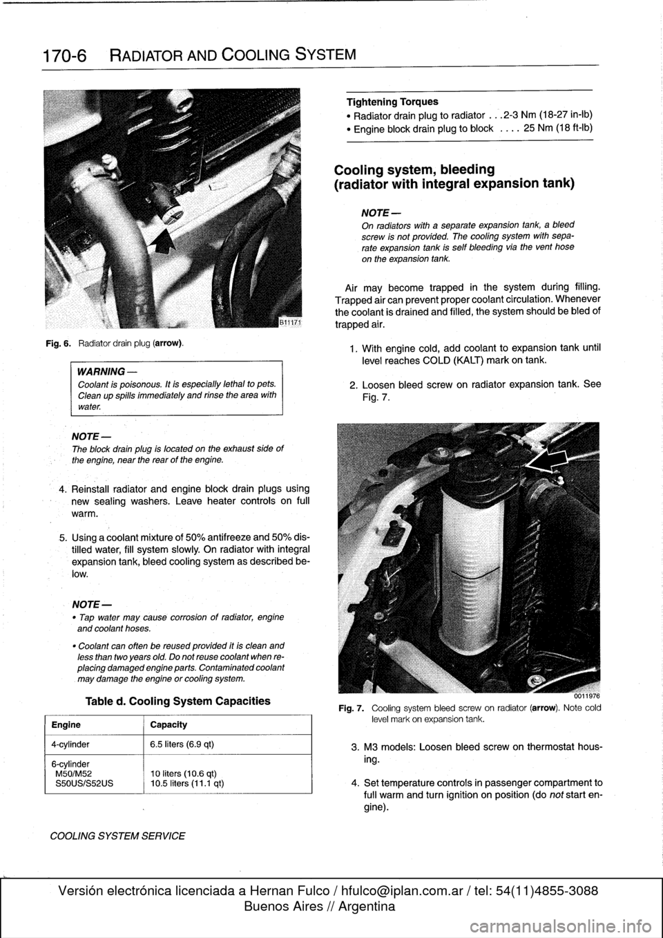
Fig
.
6
.
Radiator
drain
plug
(arrow)
.
WARNING
-
Coolant
is
poisonous
.
Itis
especially
lethal
to
pets
.
Cleanup
spills
immediately
and
rinse
the
area
with
water
.
NOTE
-
The
block
drain
plug
is
located
on
the
exhaust
side
of
the
engine,
near
the
reas
of
the
engine
.
4
.
Reinstall
radiator
and
engine
block
drain
plugsusing
new
sealing
washers
.
Leave
heater
controis
on
full
warm
.
5
.
Using
a
coolantmixture
of
50%
antifreeze
and
50%
dis-
tilled
water,
fill
system
slowly
On
radiator
with
integral
expansion
tank,
bleed
cooling
system
as
described
be-
low
.
NOTE-
"
Tap
water
may
cause
corrosion
of
radiator,
engine
and
coolant
hoses
.
"
Coolant
can
often
be
reused
provided
itis
clean
and
less
than
twoyears
old
.
Do
not
reuse
coolant
when
re-
placing
damaged
engine
parts
.
Contaminated
coolant
may
damage
the
engine
or
cooling
system
.
Tabled
.
Cooling
System
Capacities
Engine
j
Capacity
4-cylinder
1
6
.5
liters
(6.9
qt)
6-cylinder
M50/M52
10
liters
(10
.6
qt)
S50US/S52US
10
.5
liters
(11
.1
qt)
COOLING
SYSTEM
SERVICE
Tightehing
Torques
"
Radiator
drain
plug
to
radiator
...
2-3
Nm
(18-27
in-lb)
"
Engine
block
drain
plug
to
block
.
.
..
25
Nm
(18
ft-Ib)
Cooling
system,
bleeding
(radiator
with
integral
expansion
tank)
NOTE
-
On
radiators
with
a
separate
expansion
tank,
ableed
screw
is
not
provided
.
The
cooling
system
with
sepa-
rate
expansion
tank
is
self
bleeding
via
the
vent
hose
on
the
expansion
tank
.
Air
maybecome
trapped
in
the
system
during
filling
.
Trapped
air
can
prevent
proper
coolant
circulation
.
Whenever
the
coolant
is
drained
and
filled,
the
system
should
be
bled
of
trapped
air
.
1
.
With
engine
cold,
add
coolant
to
expansion
tank
until
level
reaches
COLD
(KALT)
mark
on
tank
.
2
.
Loosen
bleed
screw
on
radiator
expansion
tank
.
See
Fig
.
7
.
0011976
Fig
.
7
.
Cooling
system
bleed
screwon
radiator
(arrow)
.
Note
cold
level
mark
on
expansion
tank
.
3
.
M3
models
:
Loosen
bleed
screw
on
thermostathous-
ing
.
4
.
Set
temperature
controls
in
passenger
compartment
to
fui¡
warm
and
turn
ignition
on
position
(do
not
start
en-
gine)
.
Page 217 of 759
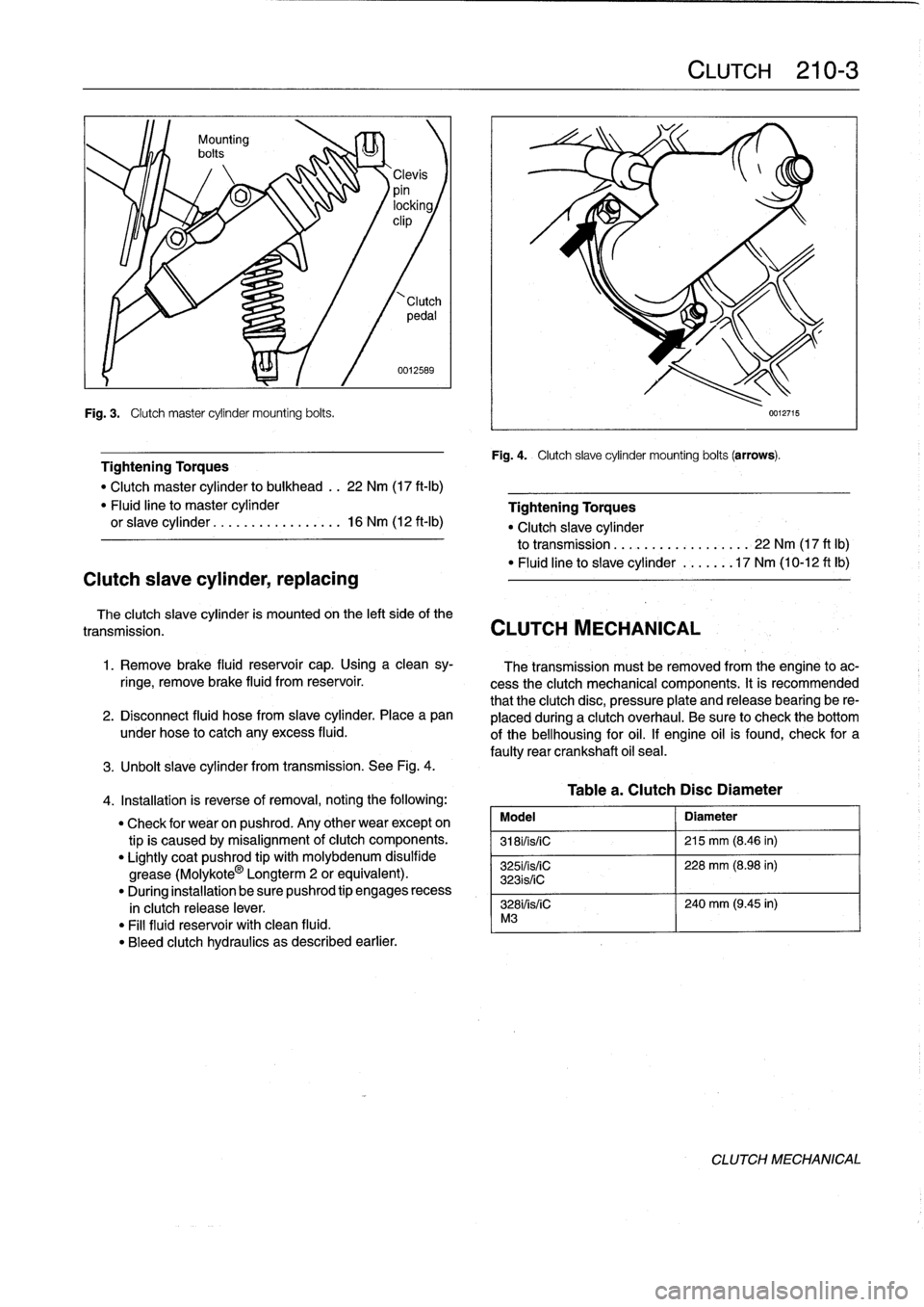
Fig
.
3
.
Clutch
master
cylinder
mounting
bolts
.
Clutch
slave
cylinder,
replacing
0012589
Tightening
Torques
"
Clutch
master
cylinder
to
bulkhead
..
22
Nm
(17
ft-Ib)
"
Fluid
line
to
master
cylinder
orslave
cylinder
.................
16
Nm
(12
ft-1b)
The
clutch
slave
cylinder
is
mounted
on
the
left
side
of
the
transmission
.
CLUTCH
MECHANICAL
1
.
Remove
brake
fluid
reservoir
cap
.
Using
a
clean
sy-
ringe,
remove
brake
fluid
from
reservoir
.
2
.
Disconnect
fluid
hose
from
slave
cylinder
.
Place
a
pan
under
hose
to
catch
any
excess
fluid
.
3
.
Unbolt
slave
cylinder
from
transmission
.
See
Fig
.
4
.
4
.
Installation
is
reverse
of
removal,
noting
the
following
:
"
Check
for
wear
on
pushrod
.
Any
other
wear
except
on
tipis
caused
by
misalignment
of
clutch
components
.
"
Lightly
coat
pushrod
tip
with
molybdenum
disulfide
grease
(Molykote
0
Longterm
2
or
equivalent)
.
"
During
installation
be
sure
pushrod
tip
engages
recess
in
clutch
release
lever
.
"
Fill
fluid
reservoir
with
clean
fluid
.
"
Bleed
clutch
hydraulics
as
described
earlier
.
CLUTCH
210-
3
Fig
.
4
.
Clutch
slave
cylinder
mounting
bolts
(arrows)
.
Tablea
.
ClutchDisc
Diameter
Model
Diameter
3181/is/iC
215
mm
(8
.46
in)
325i/is/iC
228
mm
(8
.98
in)
323is/iC
328i/is/iC
240
mm
(9
.45
in)
M3
0012715
Tightening
Torques
"
Clutch
slave
cylinder
to
transmission
.
.
................
22
Nm
(17
ft
lb)
"
Fluid
line
to
slave
cylinder
......
.17
Nm
(10-12
ft
lb)
The
transmission
must
be
removed
from
the
engine
to
ac-
cess
the
clutch
mechanical
components
.
It
is
recommended
that
the
clutch
disc,
pressure
plate
and
release
bearing
be
re-
placed
duringa
clutch
overhaul
.
Be
sure
to
check
the
bottom
of
the
bellhousing
for
oil
.
If
engine
oil
is
found,
check
for
a
faulty
rear
crankshaft
oil
seal
.
CLUTCH
MECHANICAL
Page 229 of 759
AUTOMATIC
TRANSMISSION
240-1
240
Automatic
Transmission
GENERAL
.....
.
.
.
.
.
.
.
.
.
.
.
.
.
.........
.
240-1
TRANSMISSION
REMOVAL
AND
INSTALLATION
..................
.
.
.
.
.240-4
TRANSMISSION
SERVICE
.
.
.
.
.
.......
.
240-1
Transmission,
removing
and
installing
....
.
.
.240-4
ATF
leve¡,
checking
..
.
.
.
.
.
.
.
.
.
..........
240-1
ATF,
draining
and
filling
.
.
.
.
.
.
.
..........
240-2
TABLE
a
.
Automatic
Transmission
Gear
Ratios
.......
..
.
.
240-1
GENERAL
TRANSMISSION
SERVICE
lo
Automatic
transmissions
are
identified
by
code
letters
ATF
leve¡,
checking
foundon
a
data
plate
located
on
the
sideof
thetransmission
case,
behind
the
manual
valve
lever
.
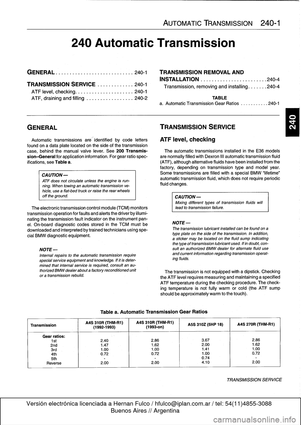
See
200Transmis-
The
automatic
transmissions
installed
in
the
E36
models
sion-General
for
application
information
.
Forgear
ratio
spec-
are
normally
filled
with
Dexron
III
automatic
transmission
fluid
ifications,
see
Table
a
.
(ATF),
although
alternative
fluids
have
been
installed
from
the
factory,
depending
on
transmission
type
and
model
year
.
CAUTION-
Some
transmíssions
are
filled
with
a
special
BMW
"lifetime"
ATF
does
not
circulate
unless
the
engine
is
run-
automatic
transmission
fluid,
which
does
not
require
periodic
ning
.
When
towing
an
automafic
transmission
ve-
fluid
changes
.
hicle,
usea
flat-bed
truck
or
ralse
the
rear
wheels
off
the
ground
.
CAUTION-
Mixing
different
types
of
transmission
fluids
will
The
electronic
transmission
control
module
(TCM)
monitors
lead
to
transmission
failure
.
transmissionoperation
for
faults
and
alerts
the
driver
by
illumi-
nating
the
transmission
fault
indicator
on
the
instrument
pan-
el
.
On-board
diagnostic
codes
stored
in
the
TCM
mustbe
NOTE-
downloaded
and
interpreted
by
trained
technicians
using
spe-
The
transmission
lubricant
instafed
can
be
foundona
cial
BMW
diagnostic
equipment
.
type
plate
on
the
side
of
the
transmission
.
In
addition,
a
sticker
may
be
located
on
the
fluid
sump
indicatingthe
typeof
transmission
lubricant
used
.
Ifin
doubt,
con
NOTE-
sult
an
authorized
BMW
dealer
for
altemate
fluid
use
Internal
repairs
to
the
automatic
transmission
require
and
current
information
regardingtransmission
operat-
special
service
equipment
and
knowledge
.
If
it
is
deter-
ing
fluids
.
mined
thatinterna¡
service
is
required,
consult
en
au-
thorízedBMWdealerabouta
factoryreconditioned
unit
The
transmission
is
not
equipped
with
a
dipstick
.
Checking
or
a
transmission
rebuild
.
the
ATF
leve¡
requires
measuring
and
maintaining
a
specified
ATF
temperature
during
the
checking
procedure
.
The
check-
ing
temperature
is
not
fully
warm
orcold
(the
ATF
sump
should
be
approximately
warm
to
the
touch)
.
Table
a
.
Automatic
Transmission
Gear
Ratios
Transmission
MS
310R
(THM-R1)
MS
310R
(THM-Rl)
MS
310Z(5HP
18)
I
MS
270R
(THM-R1)
(1992-1993)(1993-on)
Gear
ratios
:
1st
2
.40
2
.86
3
.67
2
.86
2nd
1
.47
1
.62
2
.00
1
.62
3rd
1
.00
1
.00
1.41
1
.00
4th
0
.72
0
.72
1
.00
0
.72
5th
-
-
0
.74
-
Reverse
2
.00
2
.00
4
.10
2
.00
TRANSMISSIONSERVICE
Page 253 of 759
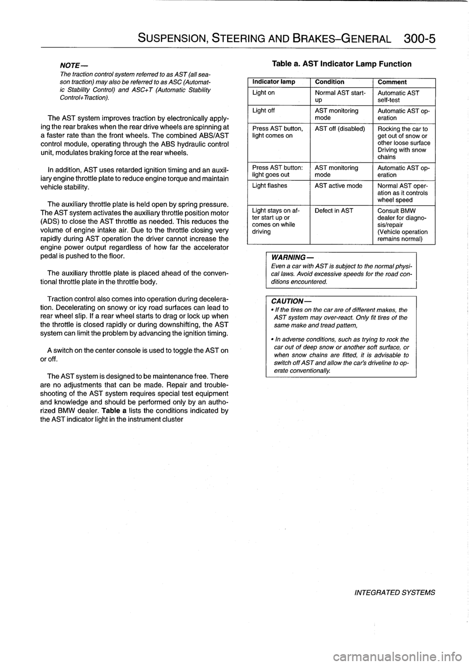
NOTE-
The
traction
control
system
referred
to
as
AST
(all
sea-
son
traction)
may
also
be
referred
to
as
ASC
(Automat-
ic
Stability
Control)
and
ASC+T
(Automatic
Stability
Control+Traction)
.
The
AST
system
improves
traction
by
electronically
apply-
ing
the
rear
brakes
when
therear
drive
wheels
are
spinning
at
a
faster
rate
than
the
front
wheels
.
The
combined
ABS/AST
control
module,
operating
through
the
ABS
hydraulic
control
unit,
modulates
braking
force
at
therear
wheels
.
In
addition,
AST
uses
retarded
ignition
timing
and
an
auxil-iary
engine
throttle
plate
to
reduceengine
torque
and
maintain
vehicle
stability
.
The
auxiliary
throttle
plate
is
held
open
by
spring
pressure
.
The
AST
system
actívates
the
auxiliary
throttie
position
motor
(ADS)
to
cose
the
AST
throttle
as
needed
.
This
reduces
the
volume
of
engine
intake
air
.
Due
to
the
throttle
closing
very
rapidly
during
AST
operationthe
driver
cannot
increase
theengine
power
output
regardless
of
how
far
theaccelerator
pedal
is
pushed
to
the
floor
.
The
auxiliary
throttle
plate
is
placed
ahead
of
the
conven-
tional
throttle
plate
in
the
throttle
body
.
Traction
control
also
comes
into
operationduringdecelera-
tion
.
Decelerating
on
snowy
or
icy
road
surfaces
can
lead
to
rear
wheel
slip
.
If
a
rear
wheel
startsto
drag
or
lock
up
when
the
throttle
is
closed
rapidly
orduringdownshifting,the
AST
system
can
limit
the
problem
by
advancing
the
ignition
timing
.
A
switch
on
the
center
console
is
used
to
togglethe
AST
on
or
off
.
The
AST
system
is
designed
to
be
maintenance
free
.
There
are
no
adjustments
that
can
be
made
.
Repair
and
trouble-
shooting
of
the
AST
system
requires
special
test
equipment
andknowledgeand
should
be
performed
only
by
an
autho-
rized
BMW
dealer
.
Table
a
lists
theconditions
indicated
by
the
AST
indicator
light
in
the
instrument
cluster
SUSPENSION,
STEERING
AND
BRAKES-GENERAL
300-5
Tablea
.
AST
Indicator
Lamp
Function
Indicator
lamp
1
Condition
1
Comment
Light
on
Normal
AST
start-
Automatic
AST
up
self-test
Light
off
AST
monitoring
Automatic
AST
op-
mode
eration
Press
AST
button,
AST
off
(disabled)
Rocking
the
car
tolight
comes
on
getout
of
snow
or
other
loose
surface
Driving
with
snow
chains
Press
AST
button
:
AST
monitoring
Automatic
AST
op-
light
goes
out
I
mode
eration
Light
flashes
AST
active
mode
I
Normal
AST
oper-
ation
as
it
controls
wheel
speed
Light
stays
on
af-
Defect
in
AST
Consult
BMW
ter
start
up
or
dealer
for
diagno-
comes
on
while
sis/repair
driving
(Vehicle
operation
remains
normal)
WARNING
-
Even
a
car
with
AST
is
subject
to
the
normal
physi-
cal
laws
.
Avoid
excessive
speeds
for
the
road
con-
ditions
encountered
.
CAUTION-
"
If
the
tires
on
the
carare
of
different
makes,
the
AST
system
may
over-react
.
Only
fit
tires
of
the
same
make
and
tread
pattem,
"In
adverse
conditions,
such
as
trying
to
rock
the
car
outof
deep
snow
or
another
soft
surface,
or
when
snow
chainsare
fitted,
it
is
advisable
to
switch
off
AST
and
allow
the
cars
driveline
to
op-
erate
conventionally
.
INTEGRATED
SYSTEMS
Page 291 of 759
Brake
rotor,
removing
and
installing
.
.
.
.
.
.
.
.
340-7
MASTER
CYLINDER
............
.
.
.
.
.
.
.340-7
Master
cylinder,
removing
and
installing
.
...
.
340-7
GENERAL
TROUBLESHOOTING
WARNING
-
"
Although
semi-metallic
and
metallic
Brake
friction
materials
in
Brake
pads
or
shoes
no
longer
con-
tain
asbestos,
they
produce
dangerous
dust
.
"
Brake
fluid
is
poisonous,
highly
corrosive
and
dangerous
to
the
environment
Wear
safety
glasses
and
rubber
gloves
when
working
with
Brake
fluid
.
Do
not
siphonBrake
fluid
with
your
mouth
.
Immediately
clean
away
any
fluid
spilled
on
painted
surfaces
and
wash
with
water,
asBrake
fluid
will
remove
paint
.
"
Always
use
new
Brake
fluid
froma
fresh,
un-
opened
container
.
Brake
fluid
will
absorb
mois-
ture
from
the
air
.
This
canlead
to
corrosion
problems
in
the
brakingsystem,
and
will
also
low-
er
the
Brake
fluid's
boiling
point
.
Dispose
of
Brake
fluid
properly
.
"
Do
notreuse
self-locking
nuts,bolts
or
fasteners
.
They
are
designed
to
be
used
only
once
and
may
failif
reused
.
Always
replace
them
with
new
self-
locking
fasteners
.
BMW
E36
models
areequipped
with
vacuum
power-assist-
ed
four-wheel
disc
brakes
with
an
integral
Antilock
Brake
Sys-
tem
(ABS)
.
Single-pistoncalipers
act
on
solid
or
vented
front
rotors
and
solid
rear
rotors
.
A
brake
pad
wear
sensor
for
each
axle
indicates
when
brake
padsneed
replacement
.
The
dual
drum-type
parking
brakesystem
is
integrated
with
the
rear
brake
rotors
.
NOTE-
M3
models
havevented
directional
Brake
rotors
on
the
rearaxle
as
well
ason
the
front
.
340
Brakes
BRAKES
340-1
GENERAL
.
.
.
.
.
.
.........
.
.
.
..........
340-1
BRAKE
BOOSTER
.........
.
.
.
.
.
...
.
.
.
.
340-8
TROUBLESHOOTING
.......
.
......
.
...
340-1
Brake
booster,
removing
and
installing
....
.
.
340-8
PARKING
BRAKE
.
.....
.
...
.
.
.
.....
.
.
.
340-10
BLEEDING
BRAKES
.
.
.
.
.
.
.
.
..........
340-3
Parking
brake,adjusting
.
.
.
.
.
.
.
.
.
.
.....
.
340-10
Pressure
bleeding
brakes
Parking
brake
shoes,
removing
and
installing
.
340-11(except
cars
with
AST)
.
.
.
.
.
.
.
.
.
...
.
.
.
.
.340-3
Parking
Brake
cable,
replacing
.
.
.
.
.
.
.
.
.
.
.
.
340-11
BRAKE
PADS,
CALIPERS,
ANTILOCK
BRAKE
SYSTEM
(ABS)
.
.
.
.340-11
AND
ROTORS
..........
.
.......
.
.
.
.
.
.
.
340-3
ABS
System
Inspection
.
...
.
.......
.
.
.
..
340-12
Brake
pads,
replacing
............
.
.
.
.
.
.
.
340-4
ABS
wheel
speed
sensors,
replacing
.
.
.
.
..
340-12
Brake
caliper,
removing
and
installing
.
..
..
.
340-6
TABLES
a
.
Brake
System
Troubleshooting
.....
...
.
.
.....
.340-2
b
.
Brake
Rotor
Reconditioning
Specifications
.
.....
.340-7
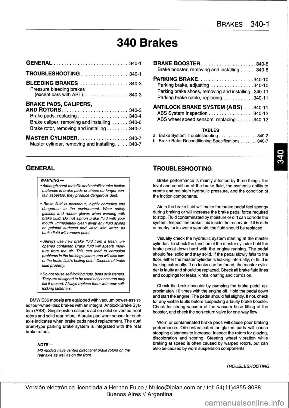
Brakeperformance
is
mainly
affected
by
three
things
:
the
leve¡
and
condition
of
the
brake
fluid,
the
system's
abilíty
to
create
and
maintain
hydraulic
pressure,
and
the
condition
of
the
friction
components
.
Air
in
the
Brake
fluid
will
make
the
Brake
pedal
feel
spongy
during
braking
or
will
increase
the
Brake
pedalforce
required
to
stop
.
Fluid
contaminated
by
moisture
or
dirt
can
corrode
the
system
.
Inspect
the
Brake
fluid
inside
the
reservoir
.
Ifit
is
dirty
or
murky,
or
is
over
a
year
old,
the
fluid
should
be
replaced
.
Visually
check
the
hydraulic
system
startingat
the
master
cylinder
.
To
check
the
function
of
the
master
cylinder
hold
the
brake
pedal
down
hard
with
the
engine
running
.
The
pedal
should
feelsolid
and
stay
solid
.
If
the
pedal
slowly
falls
to
the
floor,
either
the
master
cylinder
is
leaking
internally,
or
fluid
is
leaking
externally
.
If
no
leaks
canbe
found,
the
master
cylin-
der
is
faulty
and
should
be
replaced
.
Check
all
Brake
fluid
lines
and
couplings
for
leaks,
kinks,
chafing
and
corrosion
.
Check
the
Brake
booster
by
pumping
the
Brake
pedal
ap-
proximately
10
times
with
the
engine
off
.
Hold
the
pedal
down
and
start
the
engine
.
The
pedal
should
fa¡¡
slightly
.
If
not,
check
for
any
visiblefaults
before
suspecting
a
faulty
brake
booster
.
Check
for
strong
vacuum
at
the
vacuum
hose
fitting
at
the
booster,
and
check
the
non-retum
valve
for
one-way
flow
.
Worn
or
contaminated
brake
pads
will
cause
poor
braking
performance
.
Oil-contaminated
or
glazed
pads
will
cause
stopping
distances
to
increase
.
Inspect
the
rotors
for
glazing,
discoloration
and
scoring
.
Steering
wheel
vibration
while
braking
at
speed
is
often
caused
by
warped
rotors,
but
can
also
be
caused
byworn
suspension
components
.
TROUBLESHOOTING