fuse diagram BMW M3 1992 E36 Workshop Manual
[x] Cancel search | Manufacturer: BMW, Model Year: 1992, Model line: M3, Model: BMW M3 1992 E36Pages: 759
Page 746 of 759

RA010
CDCHANGER
67656
7
9
RE
/WHT
10LK/WHT
12
BFBR/ORG
1~fE
R
13
~
GR
/FRED
14~BRNDRG
15
i6HT
X1H~12B
1
YEL
2
BLU
3
B
FN
4
GRV
B
BLK
6
GRN
7
VIO
B
NCA
D
RED
10
WIT
X18529
NCA
1
YEL/RED
2
BLU/RED
3
VELIBLK
4
WHT/BRN
SS
VI
./W
.1
VIO/BLK
6
BLUILUBLKK
ANTENNA
ELECTRICAL
WIRING
DIAGRAMS
ELE-263
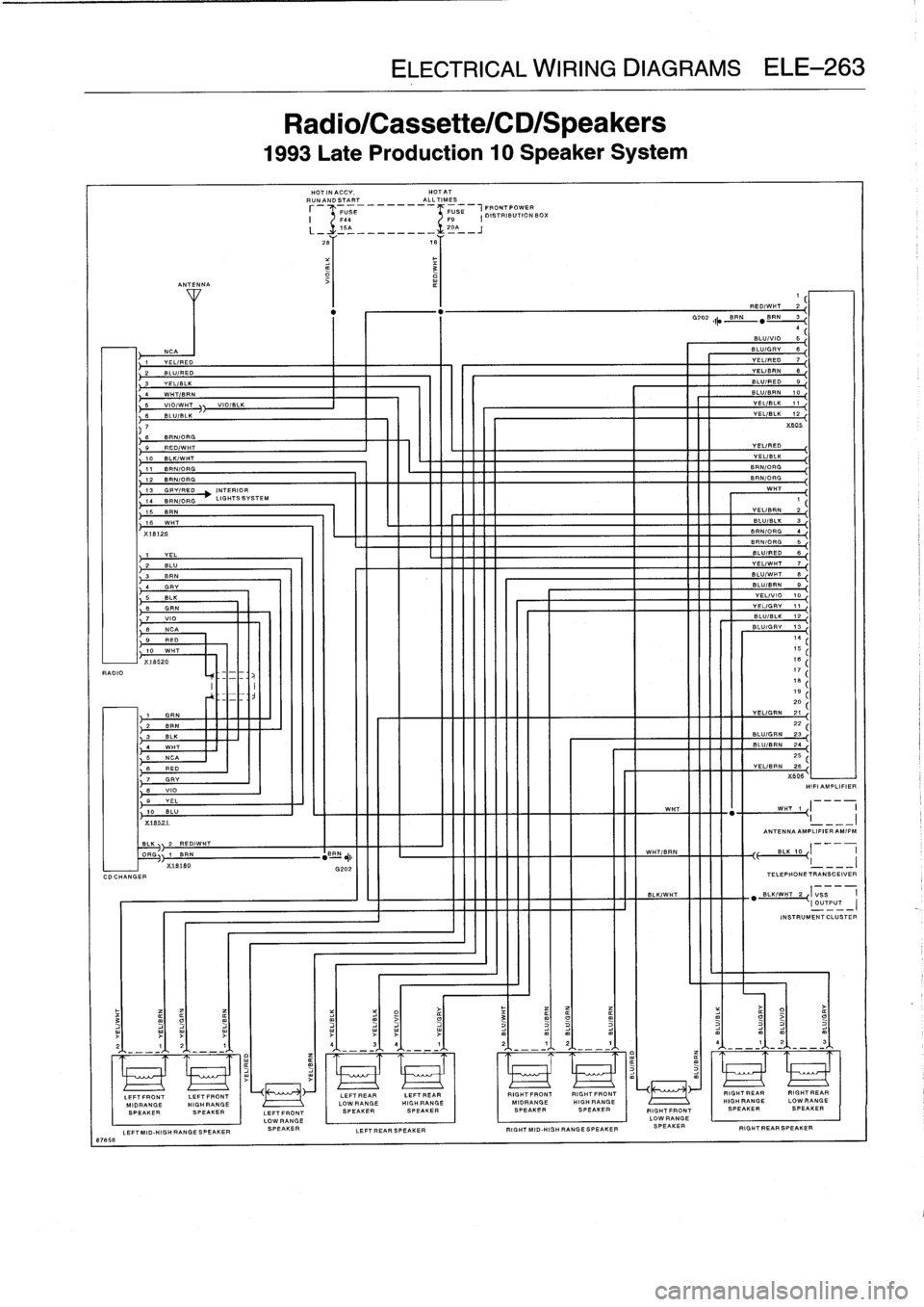
Radio/Cassette/CD/Speakers
1993
Late
Production
10
Speaker
System
HOTINACCV,
HOTAT
RUNANDSTART
_
---
-
ALLTIMES
FU0
BE
F9
-
FUSE
1
FRONTPOWER
I
DISTRIBUTION
BOX
F4
-
15A
20A
L_1
__________
.1___J
26Y
167
INEEENININEE
LEFTFRONT
LOW
RANGE
LEFTMID-HIGH
RANGE
SPEAKER
SPEAKER
LEFTREARSPEAKER
"""
.
""
.
._
"
_
"."
INEEN
VEL/RED
VEL/BLK
BRNIORG
BR
N/ORG
WHT
-..
1
VELIBRN
2
BLU/BLK
3
6RNIORG
4
BFNIORG
6
BLUIRED
6
VELIWHT
7
BLU/WHT
B
BLUIBRN
B
VEL/VIO
10
VEL/GRV
11
REDIWHT
2
,
N
"
B
RN
3
4
BLUI
iO
5~
BLU/GRV
6
VEL/RED
7
VELIBRN
8,
BLUIRED
9,
BLULU/R1
VELIBLK
1
VEL/BLK
2
X64b
BLU/BLK
1
2
,
BLU
I
GRV
13
17181B
2D
YEL/GRN
21,
B
22
LU/GRN
23
BLU/BRN
2425
VEL/BRN
26X946
H111
AMPLIFIER
WHT
WHT
1
I
--
I
ANTENNA
AMPLIFIER
AMIF
:=N
~,
WHTIBRN
BLK
10
G202
I
_~~
BLK/WHT
BL
.IWHT
TELEPHONE
E
I
VSSSC=1V=
RIGHTFRONTRIGHTFRONT
I
-
RIGHTREAR
RIGHTREAR
U
MIDRANGE
HIGH
RANGE
HIGH
RANGE
LOWRANGE
SPEAKERSPEAKER
RIGHTFRONT
SPEAKERSPEAKER
LOW
RANGE
RIGHT
MID-HIGH
RANGE
SPEAKER
SPEAKER
RIGHT
REAR
SPEAKER
Page 747 of 759

ELE-264
ELECTRICAL
WIRING
DIAGRAMS
86093
CDCHANGER
INTERIORLIGHTS
SYSTEM
HOTINACCV,RUNANDSTART
HOTATALLTIMESHOTATALLTIMES
LEFTMID-HIGH
RANGESPEAKER
T
i6
A
(OTHERS)
20A
(1997)
'
28TTT
6~'
18
VIO//
I
RED//
/
RED/
WHT/
WHT,
WHT
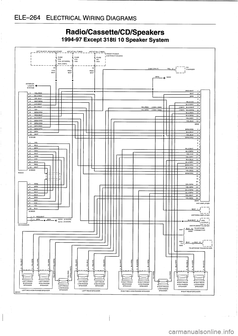
Radio/Cassette/CD/Speakers
1994-97
Except
318ti
10
Speaker
System
FUSE
F3310A
LEFTREARSPEAKER
FRONT
POWER
I
DISTRIBUTION
BOX
FUSE
LEPTREARLEFTREAR
RIGHTFRONTRIGHTFRONT
LOWRANBE
HIGH
RANGE
I
MIDRANGE
HIGHRANGE
SPEAKERSPEAKER
SPEAKERSPEAKER
19970NLY
nn
~11
G202
1
YEL/RED
2
BLU/RED
3
YEL/BLK
4
WHT/BRN
BLU/VIO
55
VIO/WHT
BLU/GRY
66
BLU/BLK
VEL/RE0
(1994-1996)
I
I
(1997)
BLU/WHT
77
YEL
-
VEL/BRN
(1994-19967
(19977
BLU/BRN
88
BRN/OR6
9
RE
D/WHT
10
BLK/WHT
11
BRN/DRG
12
B
FIN
/ORG
13
GRY/RED
14
BRNIORG
15
BRN
115
WHTX
16126
"
BLUIWHT
e
BLU/BRN
9
YELIVIO
10
YELIGRY
11
BLU/BLK
12
BLU/RED
15
VEL/RED
16
BRN/ORG
171819
zD
~
VEL/GRN
21
YELIBRN
22
,
81-11G
"
E'
BLU/BRN
24
VEL/WHT
25
VEL/BRN
26X606
-
I
I
HIFI
AMPLIFIER
WHT
1
I
I
I
YEL
3
I
--i
CHANGER
ANTENNA
AMPLIFIER
1--
-
"
BLK/WHT
2
(OUTPUT
INSTRUMENTCLUSTER
1997
r
BILK6
TELEPHONE
CONNECTOR
_REDIWHT
W
2
BRN
3
BW/RED9
BLU/BRN
10
VEL/GRY
11
YEL
L/BL1212
X
605
BRN
N/OR
BLU
U/BLK22
YELIBLLIB
3~
BRN/ORG
567
BL./
.FY
13
BRN/ORG
14
X
400
BLK
BLK
10
I
i
TELEPHONE
TRANSCEIVER
RIGHTREAR
RIGHTREAR
HIGHRANGE
LOWRANCE
RIGHTFRONT
I
SPEAKER
SPEAKERLOWRANGE
RIGHTMID-HIGH
RANGESPEAKER
SPEAKER
RIGHT
REAR
SPEAKER
Page 748 of 759

RADIO
CDCHANGER
89260
INTERIORLIGHTS
SYSTEM
HOTINACCV,RUNANDSTART
HOT
ATALLTIMES
HOTATALLTIMES
____~
___IFRONTPOWER
USE
1
FUSE
I
DISTRIBUTION
BOX
2B
VIO/
I
RED/
W
HT
WHT
REVEL/RED
DIWHT
11
WHT
2
2
BLU/RED
3
BEN
VEL/BLK
3
WHT/BRN
(1995EARLYPROD)
4
5
VIO/WHT
(19919
5LATEPROD
BLU/VIO
5
98&1997)
ELL,GRY
fi
6
BLU/BLK
BLU/WHT
VELIRED
7
7
VEL
YEL/BRN
8
8
BRN/ORG
BLU
)RED
9
9
RED/WHT
BLUIBRN
1010
BLK/WHT
YELIGRV
11
IT
SENIOR
G
12
BRN/ORG
X
606
13
GRY/FED
14
BRN/ORG
SENIOR
.
1
15
SPIN
BLU/BLK
2
16
WHT
.
YEL/BLK
3
iLB12
8
BRN/ORG
.
4
,
YEL
2
BLU
3
SPIN
4
GRY
5
BLK
6
GRN
7
VIO
NCA
9
RED
10
WHT
X18520
GHN
2
BRN
3
BLK
4
WHT
5
NCA
6
RED
7
GRY
8
VIO
9
YEL
10
BLU
K1B520
2
RED/WHT
1L
SPIN
"
SPIN
+
G211
(2000R)
G310
(4
DOOR)
FUSE
F41i5A
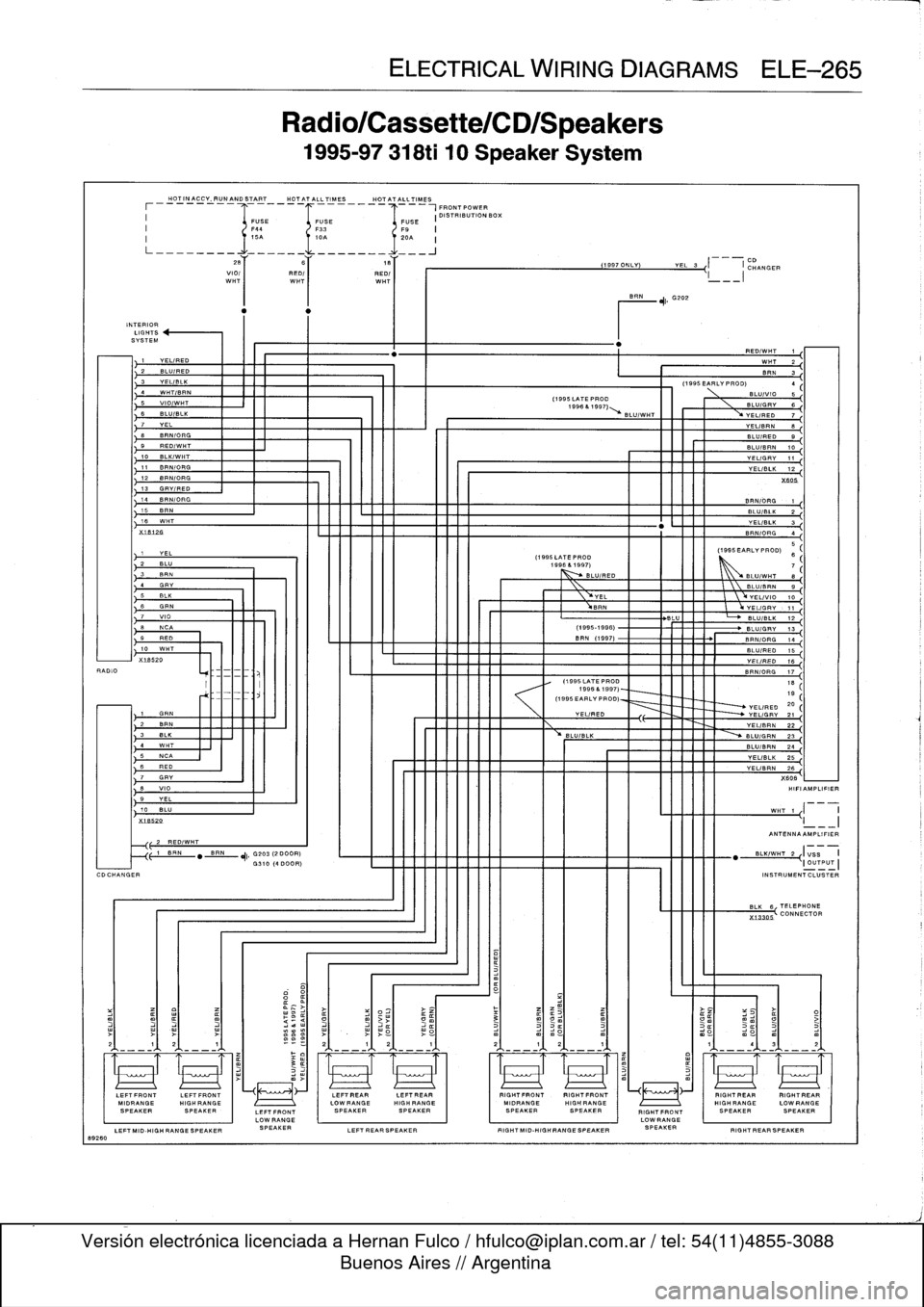
Radio/Cassette/CD/Speakers
1995-97
318ti
10
Speaker
System
RED/
WHT
F9
I
20A
I
BRN
L
VEL/GRY
,
11
BLU
BLU/BLK
12
(1995-1996)
BLU/GRY
13
BEN
(1997)
BRN/ORG
14
BLU/RED
15
YEL/
RED
16
BRN/
0-
17
ELECTRICAL
WIRING
DIAGRAMS
ELE-265
VEL/BRN
26
X606
HIFIAMPLIFIER
WHT
1
1
-
11
_1
ANTENNA
AMPLIFIER
"BLK/WHT22{IVSB
II
OUTPUT
I
INSTRUMENTCLUSTER
BLK
6
TELEPHONE
VEL/RED
YELIGRV
21
VEL/BRN
22
BLU/BLK
BLU/GRN
23
BLUIBRN
24
1111111
YELIBLK
25
O
CD
1997
ONLY)
YEL
S
I
ICHANGER
L
I__I
5
(1995LATEPROD
(1995EARLYPROD)
6
1996
&
1997)
7
BLU/RED
L
BLU/WHT
8
BLU/BRN
9
VEL
L
YEL/VIO
10
(1995LATEPROD
18
1996
&
1997)-
19
(1995
EARLY
PROD)
YELIRED
20
LEFTFRONT
I
erennen
erenrten
I
I
arennen
erenrten
RIGWRANGELOW
RANGE
SPEAKER
~~.~
.,
..
.,....
.
.,
.~
.,
----
SPEAKER
X13305
CONNECTOR
RIGHT
REAR
RIGHTREAR
HIGH
RANGE
LOWRANGE
SPEAKERSPEAKER
RIGHT
REAR
SPEAKER
Page 752 of 759

WARNING
Your
common
sense,
good
judge-
ment,
and
general
alertness
are
cru-
cial
to
safe
and
successful
service
work
.
Befcre
attempting
any
work
on
your
BMW,
read
the
warnings
and
cautions
on
page
vi¡
and
the
copyright
page
at
the
frontof
the
manual
.
Review
these
warnings
and
cautions
each
time
you
prepare
to
workon
your
BMW
.
Please
also
read
any
warnings
and
cautions
that
accom-
pany
the
procedures
in
the
manual
.
Door
glass
See
Door
windows
Door
windows
general
information
512-1
front
door
window
(2-door
models)
adjusting
512-7
removing/installing
512-5
front
door
window
(4-door
models)
initíalizing
512-1
removing/installing
512-2
rear
door
window
(4-door
models)
removing/installing
512-4
fixed
glass,
removing/installing
512-
4
rear
vent
window
or
vent
latch,
replacing
(2-door
models)
512-11
window
regulator
and
motor,
removing/installing
512-12
window
regulator
service
512-12Doorcheck
See
DoorsDoor
handle
See
Centrallocking
and
anti-theft
Door
panel
See
Doors
Doors
general
information
411-1
door
adjustment
411-2door
check,
replacing
411-2
door
panels
411-3
doors411-1
front
orrear
door,removing/installing
411-1
front
door
panel,
removing/installing
411-3
rear
door
panel,
removing/installing
411-4
rearsidepanel,
removing/installing
(two-door
model)
411-4
Drive
axle
See
Rear
suspension
Driveability
troubleshooting
See
Engine-general
Driveshaft
general
information
260-1
center
bearing
assembly,
replacing
260-6
driveshaft,
aligning
260-3
driveshaft,
installing
260-4
Driveshaft
(cont
.)
driveshaft,
removing260-4
driveshaftservice
260-3
flex-disc,
replacing
260-5
front
centering
guide,
replacing
260-7
guibo
See
flex-disc
troubleshooting260-1
ECM
(engine
control
module)
pin
assignment
See
Fuel
injection
Electrical
circuit
See
Electrical
system-general
Electrical
component
locations
general
information
610-1
auxíliary
relay
panel
610-2
component
location
table
610-9
component
locations
610-3
fuse
position
tables
610-19
fuse
positions
610-1
relay
positions
610-2
splice
panel,
left
610-2
splice
panel,
right
610-3
Electrical
system-general
general
information
600-1
continuity,
checking
600-5
electrical
test
equipment
600-2
safety
precautions
600-1
short
circuits
600-5
short
circuit,
testing
with
ohmmeter
600-6
short
circuit,
testing
with
voltmeter
600-6
troubleshooting
600-3
voltage,
measuring600-4
voltage
and
polarity
600-1
voltage
and
voltage
drops
600-4
voltage
drop,
testing
600-4
wiring
codes
and
abbreviations
600-2
wiring
diagrams
600-2
wiring,
fuses
and
relays
600-1
Electrical
wiring
diagrams
general
information
ELE-1
wiring
diagrams
ELE-2
ABS
ELE-117
ABS/AST
ELE-120
airbag
(supplemental
restraint
system)
ELE-140
air
conditioning
and
heating
ELE-
129
anti-theft
(Alpine)
system
ELE-144
anti-theft
(EWS
II)
ELE-150
body
computer
module
ELE-176
charging
system
ELE-67
convertible
top
ELE-253
cruise
control
ELE-112
data
link
connector
ELE-86
engine
cooling
ELE-94
engine
management
ELE-70
exterior
lights
ELE-194
ground
distribution
ELE-35
headlights/foglights
ELE-180
INDEX
3
Electrical
wiring
diagrams
(cont
.)
heated
seats
ELE-245
horns
ELE-153
instrument
panel
ELE-165
interior
lights/illumination
ELE-211
lumbar
control
ELE-247
on-board
computer
ELE-173
park
ventilation
ELE-139
power
distribution
ELE-2
power
door
locks
ELE-226
power
mirrors
ELE-241
power
seats
ELE-243
power
sunroof
ELE-248
power
windows
ELE-231
radio/cassette/CD/speakers
ELE-
255
rear
window
defogger
ELE-160
shift
interlock
ELE-110
starting
ELE-63
transmission
electronics
ELE-96
warning
systems`
.
chimes
ELE-178
wiper/washer
ELE-154
Emergencies
See
Fundamentals
for
the
do-it-
yourself
owner
Engine-general
general
information
100-1
air
flow
measurement
and
vacuum
leaks
100-12
basic
engine
settings
100-11
basic
requirements
100-11
battery
voltage
100-12connecting
rods
and
pistons
100-1
cooling
system
100-5
cylinder
block
and
crankshaft100-1
cylinder
compression,
checking
100-6
cylinder
head
and
valvetrain
100-2
DISA
(dual
resonance
intake
system)
100-3,130-3
driveability
troubleshooting
100-8
engine
management
system
100-3
fuel
delivery
100-5
fuel
supply
100-14ground
connections
100-13
ignition
100-5
lubrication
system100-5
mechanical
troubleshooting
100-5
on-board
diagnostics
(OBD)
100-8
oxygen
sensors
100-11
preventive
maintenance
100-11
VANOS
(variable
valve
timing)
100-2warningsand
cautions
100-5
wiring
andharness
connections100-
13Engine
control
module
(ECM)
See
Fuel
injection
Engine
removal
and
installation
general
information
110-1
engine,
removing/installing(4-cylinder
engines)
110-1
engine,
removing/installing
(6-cylinder
engines)
110-4
Engine
coolant
temperature
(ECT)
sensor
See
Fuel
injection
Engine
hood
See
Fenders,
enginehood