boot BMW M3 1992 E36 Owner's Manual
[x] Cancel search | Manufacturer: BMW, Model Year: 1992, Model line: M3, Model: BMW M3 1992 E36Pages: 759
Page 300 of 759
340-
1
0
BRAKES
PARKING
BRAKE
The
parking
brake
is
a
brake
drum
system
integrated
into
the
rear
brake
rotors
.
See
Fig
.
14
.
Adjustment
of
the
shoes
may
benecessary
compensate
for
wear
.
The
parking
brake
should
also
be
adjusted
any
time
the
cable,
the
rear
brake
rotor,
or
the
parking
brake
shoes
are
re-
placed
.
Lower
Parking
brake
Parking
brake
retum
shoe
actuator
spring
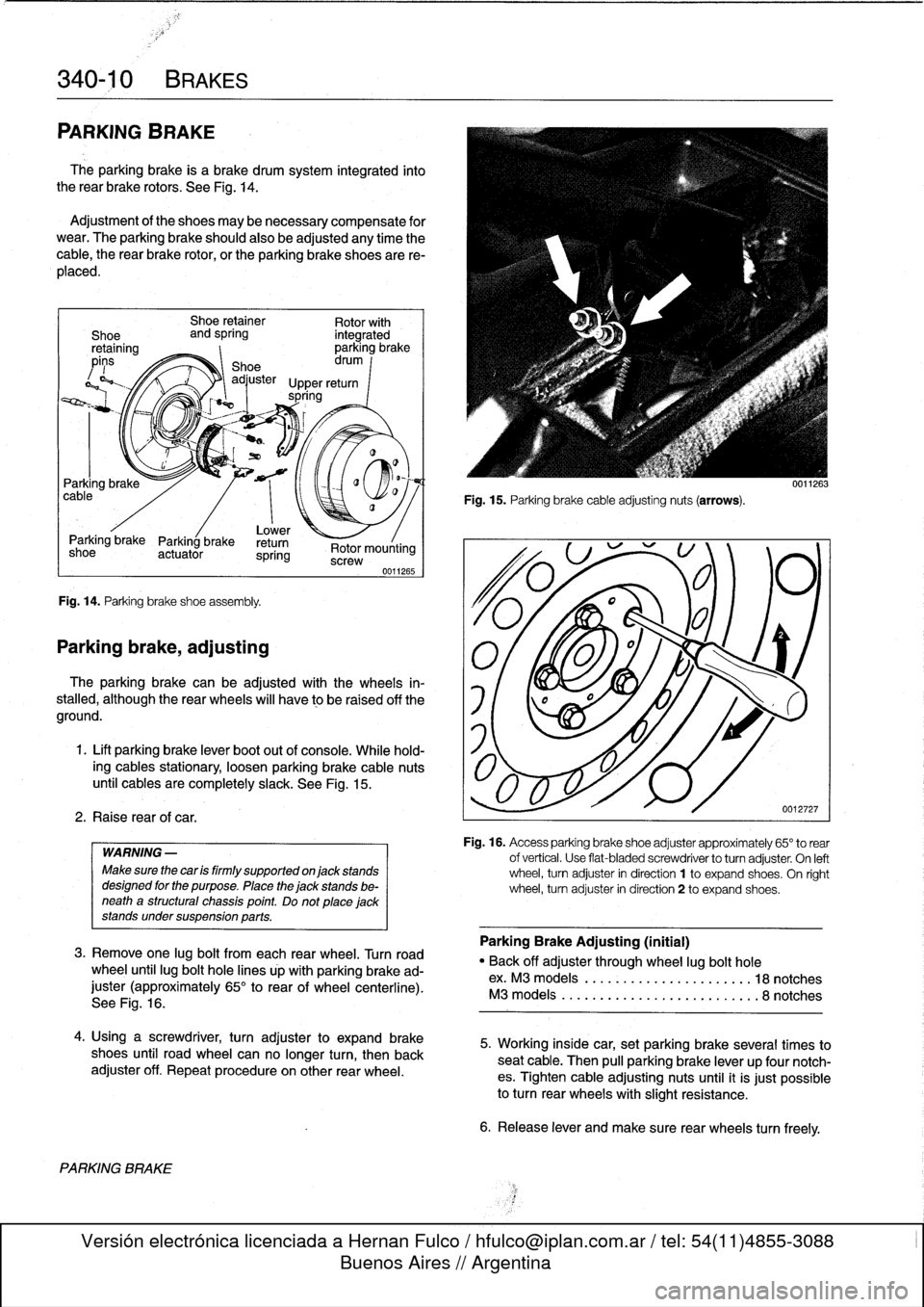
Fig
.
14
.
Parking
brake
shoeassembly
.
Parking
brake,
adjusting
2
.
Raise
rearof
car
.
PARKING
BRAKE
Shoe
retainer
Rotor
with
and
spring
integrated
parking
brake
Shoe
drum
I
adjuster
Upper
return
spring
-í
<~
:
:
Rotor
mounting
screw
WARNING
-
Make
sure
the
car
is
firmly
supported
on
jack
stands
designed
for
the
purpose
.
Place
the
jack
stands
be-
neatha
structural
chassis
point
.
Do
not
placejack
stands
undersuspension
parts
.
0011265
3
.
Remove
one
lug
bolt
from
each
rear
wheel
.
Turnroad
wheel
until
lug
bolt
hole
lines
úp
with
parking
brake
ad-
juster
(approximately
65°
to
rear
of
wheel
centerline)
.
See
Fig
.
16
.
4
.
Usinga
screwdriver,
turn
adjusterto
expand
brake
shoes
until
road
wheel
canno
longer
turn,
then
back
adjuster
off
.
Repeatprocedureon
other
rear
wheel
.
Fig
.
15
.
Parking
brake
cable
adjustingnuts
(arrows)
.
The
parking
brake
can
be
adjusted
with
the
wheels
in-
stalled,
although
the
rear
wheels
will
have
to
be
raised
off
the
1
f
l
i\
aground
.
1
.
Lift
parking
brake
lever
boot
out
of
console
.
While
hold-
ing
cables
stationary,
loosen
parking
brake
cable
nuts
until
cablesare
completely
slack
.
See
Fig
.
15
.
0011263
0012727
Fig
.
16
.
Access
parking
brake
shoe
adjuster
approxímately
65°
to
rear
of
vertical
.
Use
flat-bladed
screwdriver
to
turnadjuster
.
On
left
wheel,
turn
adjuster
in
direction
1
to
expand
shoes
.
On
ríght
wheel,
turn
adjuster
in
direction
2
to
expand
shoes
.
Parking
Brake
Adjusting
(initial)
"
Back
off
adjuster
through
wheel
lug
bolt
hole
ex
.
M3
models
.........
..
...
...
.
...
.
18notches
M3
models
............
.
.....
..
..
..
.
.
8notches
5
.
Working
inside
car,
set
parking
brake
several
times
to
seat
cable
.
Then
pull
parking
brake
lever
up
four
notch-
es
.
Tighten
cable
adjusting
nuts
until
it
is
just
possible
to
turnrear
wheels
with
slight
resistance
.
6
.
Release
lever
and
make
sure
rear
wheels
turn
freely
.
Page 301 of 759
7
.
Turn
on
ignition
.
Check
that
light
comes
on
as
soonas
4
.
Remove
parkíng
brake
shoes
as
described
above
.
lever
is
pulled
up
.
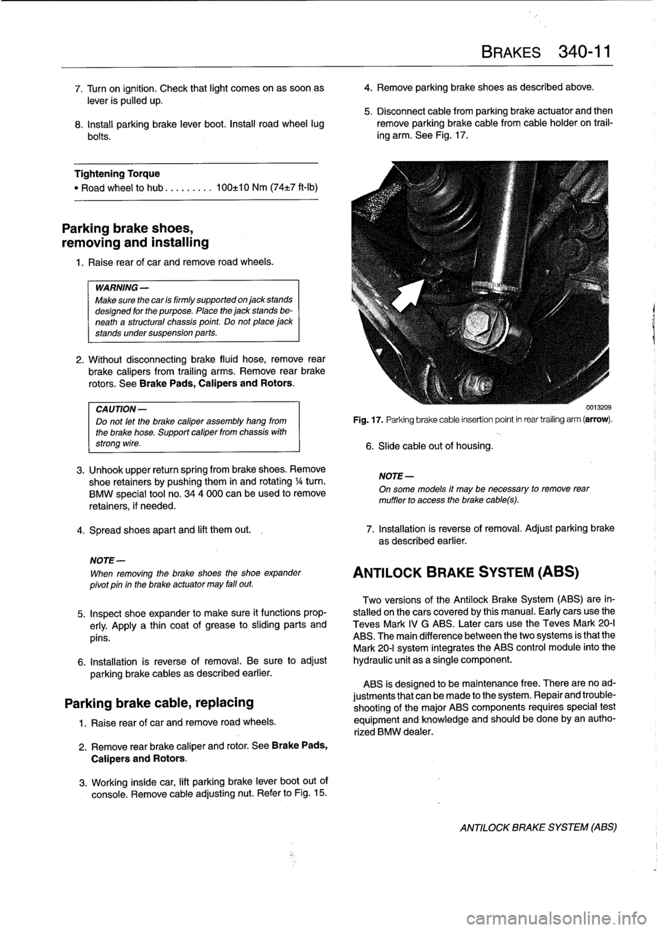
5
.
Disconnect
cable
from
parking
brake
actuator
and
then
8
.
Install
parking
brake
lever
boot
.
Install
road
wheel
lug
remove
parking
brakecable
from
cable
holder
on
trail-
bolts
.
ing
arm
.
See
Fig
.
17
.
Tightening
Torque
"
Road
wheel
to
hub
.
..
......
100±10
Nm
(74±7
ft-Ib)
Parking
brake
shoes,
removing
and
installing
1.
Raise
rear
of
car
andremove
road
wheels
.
WARNING
-
Make
sure
the
car
is
firmly
supportedon
jack
stands
designed
for
the
purpose
.
Place
the
jack
stands
be-
neath
a
structural
chassis
point
.
Do
not
place
jack
stands
undersuspension
parts
.
2
.
Without
disconnecting
brake
fluid
hose,
remove
rear
brake
calipers
from
trailing
arms
.
Remove
rear
brake
rotors
.
See
Brake
Pads,
Calipers
and
Rotors
.
CA
UTION-
Do
not
let
the
brake
caliper
assembly
hang
from
the
brake
hose
.
Support
caliper
from
chassis
with
strong
wire
.
3
.
Unhook
upper
return
spring
from
brake
shoes
.
Remove
shoe
retainers
bypushing
them
in
and
rotating
1
/4turn
.
BMW
special
tool
no
.
344
000
can
beused
to
remove
retainers,
if
needed
.
4
.
Spread
shoes
apart
and
lift
them
out
.
7
.
Installation
is
reverse
of
removal
.
Adjust
parking
brake
as
described
earlier
.
NOTE-
When
removing
the
brake
shoes
the
shoe
expander
pivot
pin
in
the
brake
actuator
may
fall
out
.
Two
versions
of
the
Antilock
Brake
System
(ABS)
are
in-
5
.
Inspect
shoe
expander
to
make
sure
it
functions
prop-
stalled
onthe
cars
coveredby
this
manual
.
Early
cars
use
the
erly
.
Apply
a
thin
coat
of
grease
tosliding
parts
and
Teves
Mark
IV
G
ABS
.
Later
cars
use
the
Teves
Mark
20-I
pins
.
ABS
.
The
main
difference
between
the
two
systems
is
that
the
Mark
20-I
system
integrates
the
ABS
control
module
into
the
6
.
Installation
is
reverse
of
removal
.
Be
sure
to
adjust
hydraulic
unit
as
a
single
component
.
parking
brake
cables
as
described
earlier
.
ABS
is
designed
to
be
maintenance
free
.
There
are
noad
Parking
brake
cable,
replacing
justments
that
canbe
made
to
the
system
.
Repair
and
trouble-
shooting
of
the
major
ABS
components
requires
special
test
1
.
Raise
rear
of
car
and
remove
road
wheels
.
equipment
and
knowiedge
and
should
be
done
by
an
autho-
rized
BMW
dealer
.
2
.
Remove
rear
brake
caliper
and
rotor
.
See
Brake
Pads,
Calipers
and
Rotors
.
3
.
Working
inside
car,
lift
parking
brake
lever
boot
out
of
console
.
Remove
cable
adjusting
nut
.
Refer
to
Fig
.
15
.
Fig
.
17
.
Parking
brake
cable
insertion
point
in
rear
trailing
arm
(arrow)
.
6
.
Slide
cable
out
of
housing
.
NOTE
-
BRAKES
340-
1
1
On
some
models
it
may
be
necessary
to
remove
rear
muffler
to
access
the
brake
cabes)
.
ANTILOCK
BRAKE
SYSTEM
(ABS)
0013209
ANTILOCK
BRAKE
SYSTEM
(ABS)
Page 329 of 759
BMW
emblem,
removing
and
installing
The
procedure
given
below
applies
to
both
front
and
rear
emblems
.
1
.
Wrap
and
of
a
screwdriver
with
tape
.
CAUTION-
Protect
hood
paint
by
coveringarea
aroundem-
blem
with
tape
.
2
.
Carefully
pryout
emblem
.
See
Fig
.
15
.
UVI1'¿.
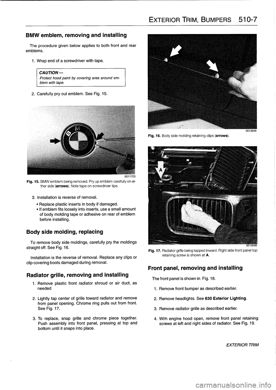
Fig
.
15
.
BMW
emblem
being
removed
.
Pry
up
emblem
carefully
on
ei-
ther
side
(arrows)
.
Note
tape
on
screwdriver
tips
.
3
.
Installation
is
reverse
of
removal
.
"
Replace
plastic
inserts
in
body
if
damaged
.
"
If
emblem
fits
loosely
intoinserts,
use
a
small
amount
of
bodymoldingtape
or
adhesiva
on
rear
of
emblem
before
installing
.
Body
side
molding,
replacing
To
remove
body
side
moldings,
carefully
pry
the
moldings
straight
off
.
See
Fig
.
16
.
Installation
is
the
reverse
of
removal
.
Replace
any
clips
or
clip
covering
boots
damaged
during
removal
.
Radiator
grille,
removing
and
installing
1
.
Remove
plastic
front
radiator
shroud
or
air
duct,
as
needed
2
.
Lightly
tap
center
of
grilla
toward
radiator
andremove
from
panel
opening
.
Chrome
ring
pulís
out
from
front
.
See
Fig
.
17
.
3
.
To
replace,
snap
grille
andchrome
piece
together
.
Push
assembly
into
front
panel,
pressing
at
top
and
bottom
until
it
snaps
into
place
.
EXTERIOR
TRIM,
BUMPERS
510-7
Fig
.
16
.
Body
sida
molding
retainingclips
(arrows)
.
-
0013048
Fig
.
17
.
Radiator
grille
being
tapped
inward
.
Right
side
front
panel
top
retaining
screw
is
shown
at
A
.
Front
panel,
removing
and
installing
The
front
panel
is
shown
in
Fig
.
18
.
1
.
Remove
front
bumper
as
described
earlier
.
2
.
Remove
headlights
.
See
630
Exterior
Lighting
.
3
.
Remove
radiator
grille
as
described
earlier
.
4
.
With
engine
hood
open,
remove
front
panel
retaining
screws
at
left
and
right
sides
of
radiator
.
See
Fig
.
19
.
EXTERIOR
TRIM
Page 345 of 759
GENERAL
This
repair
group
covers
interior
trim
removal
and
installa-
tion
procedures
.
Forremoval
and
installation
of
interior
switches,
including
interior
lighting
equipment,
see
612
Switches
and
Electrical
Accessories
.
Most
of
the
interior
trim
and
finish
paneis
are
clipped
or
screwed
into
place
.
Many
of
the
trim
retaining
clips
arede-
signed
to
be
used
only
once
.
When
removing
trim
that
is
held
in
place
with
clips,
it
is
a
good
idea
lo
have
spareson
hand
be-
fore
beginningthejob
.
CENTER
CONSOLE
The
front
section
center
console
houses
the
Multi-Informa-
tion
Display
(MID)
module,the
front
ashtray
and
cigarette
lighter
;
shifter
lever,
power
window
switches
and
the
hazard
warning
switch
.
The
rear
center
console
section
houses
the
ashtray(s)
and
covers
the
emergency
brakecable
ends
.
Center
console,
removing
and
installing
1
.
Disconnect
negative
(-)
cable
from
battery
and
cover
terminal
with
insulating
material
.
CA
UTION-
Prior
to
disconnectiog
the
battery,
read
the
battery
disconnection
cautionsgiven
at
the
front
of
this
manual
onpage
viii
.
2
.
Remove
shifter
boot
or
selectorlever
cover
.
See250
Gearshift
t-inkage
.
3
.
Remove
rear
ashtray
retaining
screws
totake
out
ash-
tray
.
Remove
rear
console
retaining
screwunder
ash-
tray
.
513
Interior
Tri
m
INTERIORTRIM
513-1
GENERAL
..
.
.....
.
.
.
.
.
.
.
.
.
.
.
......
.
.
.
513-1
DASHBOARD
.....
.
.
.
.
.
.
.
.
.
.
.
.
.
.
...
.
:
.
.513-2
Glove
compartment,removing
and
installing
.
.513-2
CENTER
CONSOLE
.
.
.
.
.
.
.
.
.
.
.........
513-1
Lower
left
dash
panel,
Center
console,
removing
and
installing
.....
513-1
removing
and
installing
.
.
.
.
.
.
.
.
.
.
.....
.
.
513-2
Dashboard,removing
and
installing
.
.
.
.
...
.
.513-3
4
.
Remove
Multi-Information
Display
module
.
See620
In-
struments
.
5
.
Remove
hazardwarning
switch
and
power
window
switches
bypushing
up
and
out
from
below
.
6
.
Remove
lower
left
dashboard
panel
and
glove
compart-
ment
as
described
later
in
this
repair
group
.
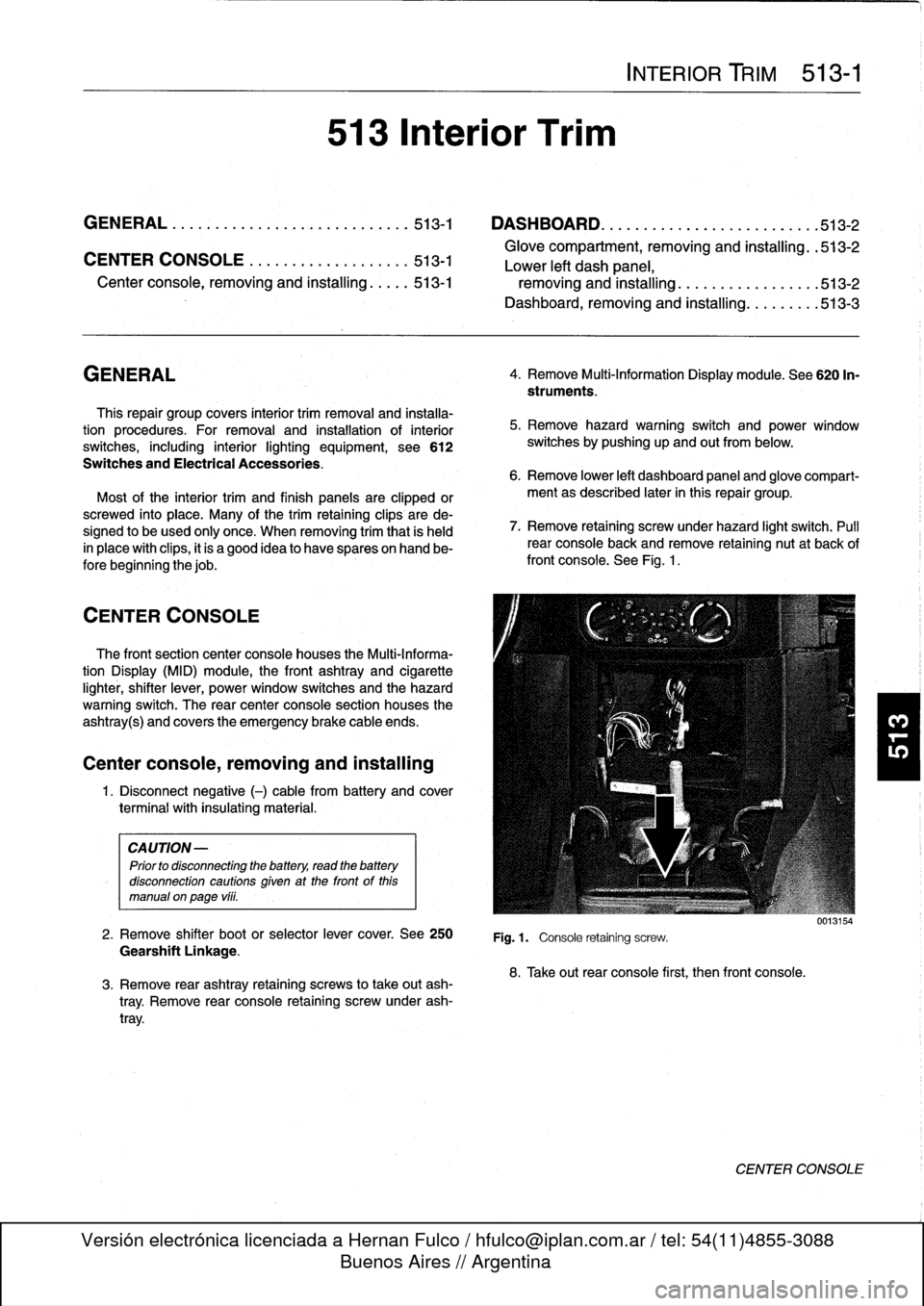
7
.
Remove
retaining
screwunder
hazard
light
switch
.
Pull
rear
console
back
and
remove
retaining
nut
at
back
of
front
console
.
See
Fig
.
1
.
Fig
.1.
Console
retaining
screw
.
8
.
Take
out
rear
console
first,
then
front
console
.
0013154
CENTER
CONSOLE
Page 382 of 759
600-2
ELECTRICAL
SYSTEM-GENERAL
CAUTION
-
"
Always
turn
off
the
engine
and
disconnect
the
negative
()
cable
from
the
batterybefore
remov-
ing
any
electrical
components
.
Disconnecting
the
battery
may
erase
fault
code(s)
stored
in
control
module
memory
.
Check
for
fault
codes
using
spe-
cial
BMW
diagnostic
equipment
.
"
Prior
to
disconnecting
the
battery,
read
the
bat-
tery
disconnection
cautions
given
at
the
front
of
this
manual
onpage
viii
.
"
Connect
and
disconnect
ignition
system
wires,
multiple
connectors,
and
ignition
test
equipment
leads
only
while
the
ignition
is
off
.
"
Do
not
disconnect
the
battery
with
engine
run-
ning
.
"
Do
not
quick-charge
the
battery
(for
boost
start-
ing)
for
longer
than
one
minute,
and
do
not
ex-
ceed
16
.5
volts
at
the
battery
with
the
boosting
cables
attached
.
Wait
at
feast
one
minute
before
boosting
the
battery
a
second
time
.
"
Do
not
usea
test
famp
that
has
a
normal
incan-
descent
bulb
to
test
circuits
contafning
electronic
components
.
The
high
electrical
consumptionof
these
test
lamps
may
damage
the
components
.
"
Do
not
use
an
analog
meter
.
Use
onfy
a
digital
multimeter
.
"
Many
of
the
solid-state
modules
are
static
sensi-
tive
.
Static
discharge
will
permanently
damage
them
.
Always
handle
the
modules
using
proper
static
prevention
equipment
and
techniques
.
"
To
avoid
damaging
harness
connectors
or
relay
panel
sockets,
use
jumper
wires
with
flat-blade
connectors
that
are
the
same
size
as
the
connec-
tor
or
relay
terminals
.
"
Always
switch
a
digital
multimeter
to
the
appropri-
ate
function
and
range
before
making
test
con-
nections
.
"
Do
not
tryto
start
the
engine
of
a
carwhich
has
been
heated
above176°F
(80°C),
(for
example,
in
a
paint
dryingbooth)
.
Allow
it
to
cool
to
normal
temperature
.
"
Disconnect
the
battery
before
dolng
any
electric
welding
on
the
car
.
"
Do
not
wash
the
engine
while
it
is
runnfng,
or
any-
time
the
ignition
is
switched
on
.
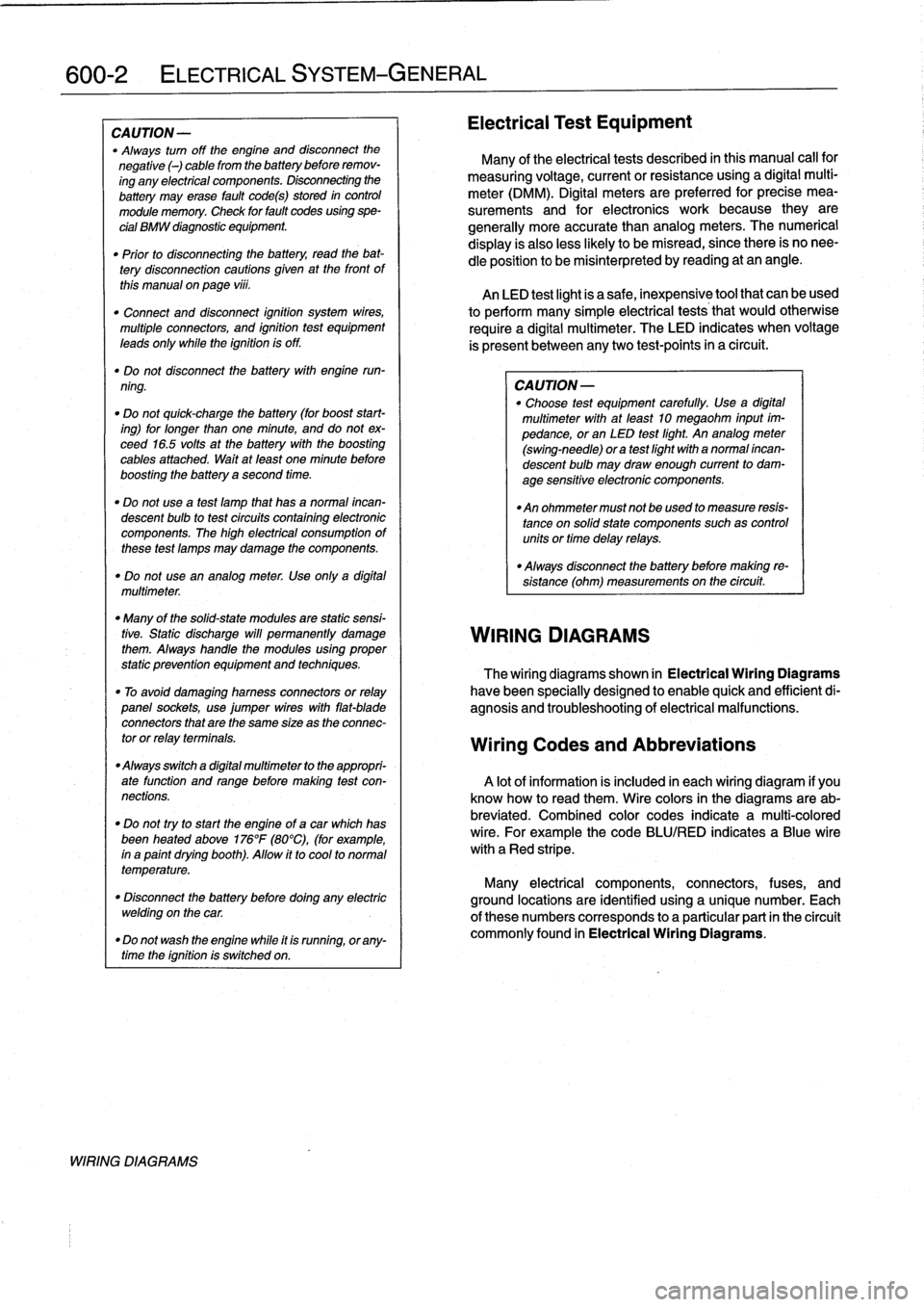
WIRING
DIAGRAMS
Electrical
Test
Equipment
Many
of
the
electrical
tests
described
in
this
manual
call
for
measuring
voltage,
currentorresistanceusing
a
digital
multi-
meter
(DMM)
.
Digital
meters
are
preferred
for
precise
mea-
surements
and
for
electronics
work
because
they
are
generally
more
accuratethan
analog
meters
.
The
numerical
display
is
alsoless
likely
to
be
misread,
since
there
is
no
nee-
dle
position
to
be
misinterpreted
by
reading
at
an
angle
.
An
LED
test
light
is
a
safe,
inexpensive
tool
that
can
be
used
to
perform
many
simple
electrical
tests
that
would
otherwise
require
a
digital
multimeter
.
The
LED
indicates
when
voltage
is
present
between
anytwo
test-points
in
a
circuit
.
CA
UTION-
"
Choose
test
equipment
carefully
.
Use
a
digital
multimeter
with
at
leadt
10
megaohm
input
im-
pedance,or
an
LED
test
light
.
An
analog
meter
(swing-need1e)
ora
test
light
with
a
normal
incan-
descent
bulb
may
draw
enough
current
to
dam-
age
sensitive
electronic
components
.
"
An
ohmmeter
must
not
beused
to
measure
resis-
tance
on
solidstate
components
suchas
controlunits
or
time
delay
relays
.
"
Always
disconnect
the
battery
before
making
re-
sístance
(ohm)
measurements
on
the
circuit
.
WIRING
DIAGRAMS
The
wiring
diagrams
shown
in
Electrical
Wiring
Diagrams
have
been
specially
designed
to
enable
quick
and
efficientdi-
agnosis
and
troubleshooting
of
electrical
malfunctions
.
Wiring
Codes
and
Abbreviations
A
lot
of
information
is
included
in
each
wiring
diagram
if
you
know
how
to
read
them
.
Wire
colors
in
the
diagrams
are
ab-
breviated
.
Combined
color
codes
indicate
a
multi-colored
wire
.
For
example
the
code
BLU/RED
indicates
a
Blue
wire
with
a
Red
stripe
.
Many
electrical
components,
connectors,
fuses,
and
ground
locations
are
identified
using
a
unique
number
.
Each
of
there
numbers
corresponds
to
a
particular
part
in
the
circuit
commonly
found
in
Electrical
Wiring
Diagrams
.
Page 433 of 759
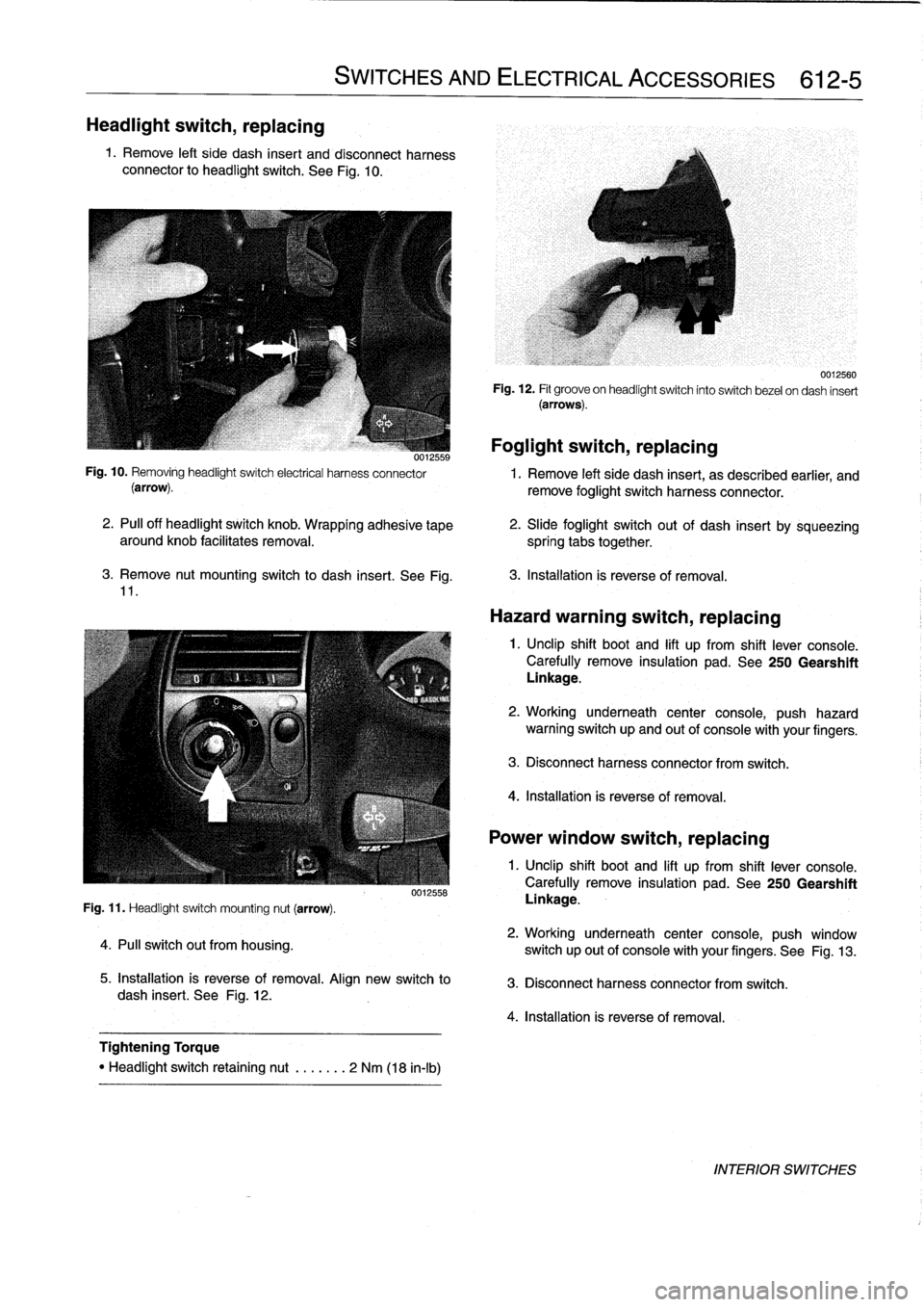
Headlight
switch,
replacing
1
.
Remove
left
side
dash
insert
and
disconnect
harness
connector
to
headlight
switch
.
See
Fig
.
10
.
3
.
Remove
nut
mounting
switch
to
dash
insert
.
See
Fig
.
11
.
Fig
.
11
.
Headlight
switch
mounting
nut
(arrow)
.
4
.
Pull
switch
out
from
housing
.
SWITCHES
AND
ELECTRICAL
ACCESSORIES
612-5
0012558
5
.
Installation
is
reverse
of
removal
.
Align
new
switch
to
dash
insert
.
See
Fig
.
12
.
Tightening
Torque
"
Headlight
switch
retaining
nut
.
......
2
Nm
(18
in-lb)
Foglight
switch,
replacing
0012559
Fig
.
10
.
Removing
headlightswitch
electrical
harness
connector
1
.
Remove
left
side
dash
insert,
as
described
earlier,
and
(arrow)
.
remove
foglight
switch
harness
connector
.
2
.
PA
off
headlight
switch
knob
.
Wrapping
adhesive
tape
aroundknob
facilitates
removal
.
spring
tabs
together
.
0012560
Fig
.
12
.
Fit
groove
on
headlightswitch
into
switch
bezel
ondash
insert
(arrows)
.
2
.
Slide
foglight
switch
out
of
dash
insert
by
sqúeezing
3
.
Installation
is
reverse
of
removal
.
Hazard
warning
switch,
replacing
1
.
Unclip
shift
boot
and
lift
up
from
shift
lever
console
.
Carefully
remove
insulation
pad
.
See
250
Gearshift
Linkage
.
2
.
Working
underneath
center
console,
push
hazard
warning
switch
up
and
out
of
console
with
your
fingers
.
3
.
Disconnect
harness
connector
from
switch
.
4
.
Installation
is
reverse
of
removal
.
Power
window
switch,
replacing
1
.
Unclip
shift
boot
and
lift
up
from
shift
lever
console
.
Carefully
remove
insulation
pad
.
See250
Gearshift
Linkage
.
2
.
Working
underneath
center
console,
push
window
switch
up
out
of
console
with
your
fingers
.
See
Fig
.
13
.
3
.
Disconnect
harness
connector
from
switch
.
4
.
Installation
is
reverse
of
removal
.
INTERIOR
SWITCHES
Page 755 of 759
6
INDEX
Ignition
system
general
information
120-1basictroubleshooting
principies
120-3camshaft
position
(CMP)
sensor
120-
6
camshaft
positíon
(CMP)
sensor,
replacing
(4-cylinder
engine)
120-6camshaft
position
(CMP)
sensor,
replacing
(6-cylinder
engines)
120-7
checking
for
spark
120-3
crankshaftposition/rpm
sensor
120-5
crankshaft
position/rpm
sensor,
testing/replacing
(front
mounted
sensor)
120-6
crankshaft
positíon/rpm
sensor,
testing
(rear
mounted
sensor)
120-6
disabling
ignition
system120-2
ignition
coil,
testing
and
replacing
(4-
cylinder
engines)
120-3
ignition
coil,
testing
and
replacing
(6-
cylinder
engines)
120-4
ignítion
firing
order
120-7
ignition
system
diagnostics
120-3
ignition
system
schematics
120-7
ignition
system
service
120-3knock
sensors,
replacing
120-7warnings
and
cautions
120-2
Inspectíon
I
and
Inspection
II
See
Maintenanceprogram
Instrumentpanel
See
interior
trim
Instruments
general
information
620-1
instrument
cluster,
removinglinstalling
620-1
instrument
cluster,
self-testing
620-1
instrument
cluster
bulbs,
replacing
620-2
multi-information
display
(MID),
620-4
multi-information
display
(MID),
removing/installing
620-4
odometer
coding
plug,
replacing
620-
2
vehicle
speed
sensor,
replacing
620-3
Intake
manifold
4-cylinder
engíne,
removing
113-3
6-cylinder
engine,
removing
113-11
See
alsoCylinder
head
removal
and
installation
Intake
air
temperaturesensor
See
Fuel
injection
Interior
trim
general
information
513-1
center
console,
removing/installing
513-1
dashboard,
removing/installing
513-3
glove
compartment,
removing/
installing
513-2
lower
left
dash
panel,
removing/
installing
513-2
J
Jump
startíng
010-12
K
Knock
sensor
See
Ignition
system
L
Leather
upholstery
See
Maíntenance
program
Leve¡
sender
See
Fuel
pump
Lubrication
system
general
information
119-1
oil
pan,
removing/installing
(4-cylinder
engines)
119-2
oil
pan,
removing/installing
(6-cylinder
engine,
1992models)119-4
oil
pan
119-2
oil
pan,
removing/installing
(6-cylinder
engine,
1993
and
later
models)
119-6
oil
pressure,
checking
119-1
oil
pressure
warningsystem,
testing
119-2
oil
pump
119-8
oil
pump,
removing/installing
(4-cylinder
engine)
119-8
oil
pump,
removing/installing
(6-cylinder
engine)
119-9
troubleshooting
119-1
M
Maíntenance
program
general
information
020-2
accelerator
and
throttle
linkage
020-13
air
filter,
replacing
020-11
automatic
transmission
fluid
020-8
automatic
transmission
service
020-18
battery,
checking
and
cleaning
020-12
battery,
replacing
020-12
BMW
service
indicator
020-2
body
and
hinges,
lubricating
020-19
brake
fluid
020-9
brake
fluid,
replacing
020-17
brake
pad/rotor
wear,
checking
020-17
brake
system,
inspecting
020-17
clutch
fluid,
checking
020-19
cooling
system
service
020-14
drive
axle
joint
boots,
inspecting
020-19
engine
coolant
(anti-freeze)
020-9
engine
drive
belts
020-13
engine
oil,
checking
leve¡
020-9
Maintenance
program
(cont
.)
engine
oil
and
filter,
changing020-9engine
oil
service
020-9
exhaust
system,
inspecting
020-18
exterior
washing020-20
final
drive
gear
oil
020-9
final
drive
oil
level,
checking
020-18
front
suspension
and
steering
linkages,
inspecting
020-18
fuel
filter,
replacing
020-16
fuel
tank
and
fuel
lines,
inspecting
020-19
¡dle
speed
020-12
inspection
I
and
inspection
11
020-2
interior
care020-20
leather
upholstery
and
trim
020-20
maintenance
tables
020-3
manual
transmission
fluid,
checking
and
filling
020-18manual
transmission
fluid
020-8
manual
transmission
service
020-18oxygensensors
020-15
parking
brake,
checking
020-17
polishing
020-20
poly-ribbed
belt,
replacing
020-13
power
steering
fluid
020-9
power
steering
fluid,
checking
leve¡
020-14
rear
suspension,
inspecting
020-18
resetting
service
indicator
020-3
seat
belts
020-20
spark
plugs,
replacing
020-11
special
cleaning
020-20
tires,
checking
inflation
pressure
020-17
tires,
rotating
020-17
v-belt,
replacing
020-13
washing
chassis
020-20waxing020-20
windshield
wiperblade
maintenance
020-19
wheels,
aligníng
020-17
Manual
transmission
See
also
Maintenance
program
See
also
Transmission-general
general
information
230-1
back-up
light
switch,
replacing
230-2
inputshaft
sea¡,
replacing
(transmission
installed)
230-5
output
shaftsea¡,
replacing
(transmission
installed)
230-4
selector
shaft
sea¡,
replacing
(transmission
installed)
230-3
transmission
fluid,
replacing
230-2
transmission
fluidlevel,
checking
230-2
transmission
fluid
service
230-1
transmission
removal
and
installation
230-5
transmission,
removing/installing
230-
6
transmission
service
230-2
Mass
air
flow
sensor
See
Fuel
Injection
Page 756 of 759
N
WARNING
Your
common
sense,
good
judge-
ment,
and
general
alertness
are
cru-
cial
to
safe
and
successful
service
work
.
Before
attempting
any
workonyour
BMW,
read
the
warnings
and
cautions
on
page
vi¡
and
the
copyright
page
at
the
front
of
the
manual
.
Review
these
warningsand
cautions
each
time
you
prepare
to
work
on
your
BMW
.
Please
also
read
any
warnings
and
cautions
that
accom-
pany
the
procedures
in
the
manual
.
Master
cylinder
See
Brakes
See
also
Clutch
Mechanical
troubleshooting
See
Engine-general
Microfilter
See
Air
conditioning
Mirror
See
Exterior
trim,
bumpers
Muffler
See
Exhaustsystem
Multi-information
display
(MID)
See
Instruments
Neutral
safetyswitch
See
Gearshift
linkage
O
Oil,
changing
See
Maintenance
program
Oil
panSee
Lubrication
system
Oil
pressure
See
Lubrication
system
Oil
pump
See
Lubrication
systemOn-board
diagnostics
(OBD)
See
Engine-general
See
alsoFuel
injection
See
also
Ignition
system
On-board
trip
computer
See
Multi-information
display
620-4
Oxygen
sensor
See
Engine-general
See
alsoFuel
injection
See
also
Maintenance
program
P
Parking
brake
See
Brakes
See
also
Maintenance
program
Parts
See
Fundamentals
for
the
do-it-
yourself
owner
Poly-ribbed
belt
See
Maintenance
program
Power
steering
See
Steering
and
wheel
alignment
Power
steering
(luid
See
Maintenance
program
R
Radiator
See
Cooling
system
Radio
general
information
650-1audio
system
650-1
radio
connector
650-6
removing/installing
650-2speakersdoor
panel
speaker,
removing/
installing
650-5
left
footwell
speaker,
removing/
installing
650-3
rear
speaker,
removing/installing
650-5
right
footwell
speaker,
removing/
installing
650-4Rearsuspension
See
also
Maintenance
program
general
information
330-1
coil
spring,
removing/installing
330-4
CV
boot,
replacing
330-8
drive
axle,
removing/installing
330-6
drive
axles
330-6
final
drive
carrier
330-12
final
drive
carrier,
removing/installing
330-12
lower
control
arm,
removing/installing
330-12
rear
shock
absorber,
removing/
installing
330-3
rear
suspension
arms
330-9
ride
heíght
330-1
shock
absorbers
and
springs
330-2
trailing
arm,
removing/installing
330-10
trailing
arm
bushing,
replacing
330-11upper
control
arm,
removing/installing
330-12
rear
wheel
bearing,
replacing
330-5
rear
wheel
bearings
330-4
Rear
view
mirror
See
Exterior
trim,
bumpers
Receiver/drivr
See
Air
conditioning
Relays
See
Electrical
component
locations
INDEX
7
Ride
height
See
Front
suspension
or
Rearsuspension
Ring
antenna
See
Central
locking
and
anti-theft
Roof
See
Convertible
top
See
also
Sunroof
Roundel
See
Exterior
trim,
bumpers
S
Seat
belts
general
information
720-1
automatic
front
seat
belt
lock
tensioners
720-2
center
rear
lap-belt,
removing/
installing
720-5
front
seat
beltreel,
removing/installing
720-3
mechanical
spring
tensioner,
disarming
720-2
rear
seat
belt,
removing/installing
(fixed
seat
back
models)
720-4
rear
seat
belt,
removing/installing
(fold-down
seat
back
models)
720-5Seats
general
information
520-1
front
seats520-1
manual
front
seat
assembly
520-3
power
front
seat
assembly
520-4
removing/installing
520-1
rear
seats
520-5
rear
seat
cushion
and
backrest,
removing/installing
(fixed
seat
backmodels)
520-5
rear
seat
cushion
and
backrest,
removing/installing
(fold-down
seat
back
models)520-5
rear
seat
backrest
side
section,
removing/installing
(fold-down
seat
back
models)520-6
Shiftinterlock
See
Gearshift
linkage
Shiftlever
See
Gearshift
linkage
Shíftlock
See
Gearshift
linkage
Shock
absorber
See
Front
suspension
See
also
Rear
suspension
Side-impact
airbag
See
Airbag
system
(SRS)
Slave
cylinder
See
Clutch
Service
indicator
See
Maintenanceprogram
Solenoid
See
Battery,
starter,
alternator
Spark
See
Ignition
system
Spark
plugs
See
Maintenance
program