warning light BMW M3 1992 E36 Repair Manual
[x] Cancel search | Manufacturer: BMW, Model Year: 1992, Model line: M3, Model: BMW M3 1992 E36Pages: 759
Page 335 of 759
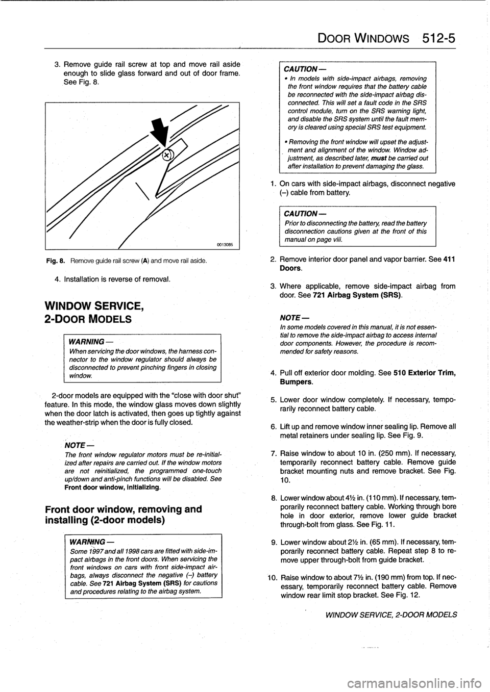
3
.
Remove
guide
rail
screw
at
top
and
move
rail
aside
enough
to
slide
glass
forward
and
out
of
door
frame
.
See
Fig
.
8
.
4
.
Installation
is
reverse
of
removal
.
WINDOW
SERVICE,
2-DOOR
MODELS
WARNING
-
When
servicing
the
door
windows,
the
hamess
con-
nector
to
the
window
regulator
shouldalwaysbe
disconnectod
to
prevent
pinching
fingers
in
closing
window
.
2-door
models
are
equipped
with
the
"close
with
door
shut"
feature
.
In
this
rriode,
the
window
glass
moves
down
slightly
when
the
door
latch
is
activated,
then
goes
up
tightly
against
the
weather-strip
when
the
door
is
fully
closed
.
Front
door
window,
removing
and
installing
(2-door
models)
WARIWNG
-
Some
1997and
a111998
cars
are
fitted
with
side-im-
pact
airbags
in
the
front
doors
.
When
servicing
the
front
windows
on
cars
with
front
side-impact
air-
bags,
always
disconnect
the
negative
(-)
battery
cable
.
See
721
Airbag
System(SRS)
for
cautions
and
procedures
relating
to
the
airbag
system
.
DOOR
WINDOWs
512-
5
CAUTION-
"In
models
with
side-impact
airbags,
removing
the
front
window
requires
fhat
the
battery
cable
be
reconnected
with
the
side-impact
airbag
dis-
connected
.
This
will
set
a
fault
code
in
the
SRS
control
module,
turn
on
the
SRS
warning
light,
and
disable
the
SRS
system
until
the
fault
mem-
ory
is
cleared
using
special
SRS
test
equipment
.
"
Removing
the
front
window
will
upset
the
adjust-
ment
and
alignment
of
the
window
.
Window
ad-justment,
as
described
later,
must
be
carried
out
after
installation
to
prevent
damaging
the
glass
.
1.
On
carswith
side-impact
airbags,
disconnect
negative
(-)
cable
from
battery
.
CAUTION-
Prior
to
disconnectiog
the
battery,
read
the
battery
disconnection
cautions
given
at
the
front
of
this
manual
on
page
viii
.
Fig
.
8
.
Remove
guide
rail
screw
(A)
and
move
rail
aside
.
2
.
Remove
interior
door
panel
and
vapor
barrier
.
See
411
Doors
.
3
.
Where
applicable,
remove
side-impact
airbag
from
door
.
See
721
Airbag
System
(SRS)
.
NOTE-
In
some
models
covered
in
this
manual,
it
is
notessen-
tial
to
remove
the
side-impact
airbag
lo
access
intemal
door
components
.
However,
the
procedure
is
recom-
mended
for
safety
reasons
.
4
.
Pull
off
exterior
doormolding
.
See
510
Exterior
Trim,
Bumpers
.
5
.
Lower
door
window
completely
If
necessary,
tempo-
rarily
reconnect
battery
cable
.
6
.
Lift
up
and
remove
window
innersealing
lip
.
Remove
all
metal
retainers
under
sealing
lip
.
See
Fig
.
9
.
NOTE
-
The
front
window
regulator
motors
must
be
re-initial-
7
.
Raise
window
to
about10
in
.
(250
mm)
.
If
necessary,
ized
after
repairs
are
carried
out
.
If
the
window
motors
temporarily
reconnect
battery
cable
.
Remove
guide
arenot
reinitialized,
the
programmed
one-touch
bracket
mounting
nuts
and
remove
bracket
.
See
Fig
.
up/down
and
anti-pinch
functions
will
be
disabled
.
See
10,
Front
doorwindow,
initializing
.
8
.
Lower
window
about
4'/2
in
.
(110mm)
.
If
necessary,
tem-
porarily
reconnect
batterycable
.
Working
through
bore
hole
in
door
exterior,
remove
lower
guide
bracket
through-bolt
from
glass
.
See
Fig
.
11
.
9
.
Lower
window
about
2'/2
in
.
(65
mm)
.
If
necessary,
tem-
porarily
reconnect
battery
cable
.
Repeat
step
8
to
re-
move
upper
through-bolt
from
guide
bracket
.
10
.
Raise
window
to
about
7
1
/2in
.
(190
mm)
from
top
.
If
nec-
essary,
temporarily
reconnect
batterycable
.
Remove
window
rear
limit
stop
bracket
.
See
Fig
.
12
.
WINDOW
SERVICE,
2-DOOR
MODELS
Page 337 of 759
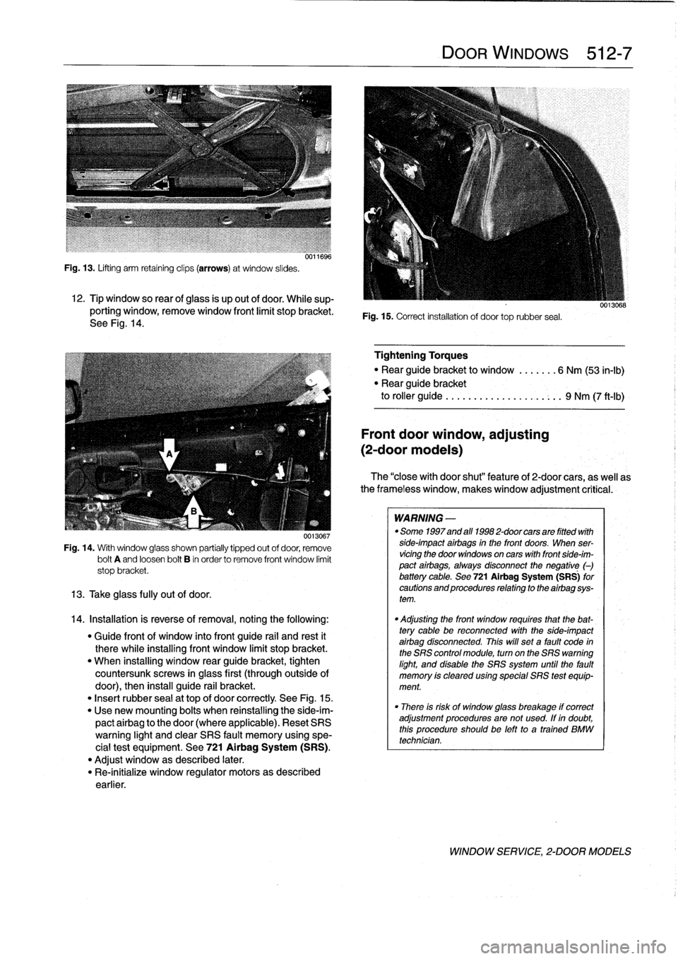
Fig
.
13
.
Lifting
arm
retaining
clips
(arrows)
at
window
slides
.
12
.
Tip
window
so
rear
ofglass
is
up
out
of
door
.
While
sup-
porting
window,
remove
window
front
limit
stopbracket
.
See
Fig
.
14
.
0013067
Fig
.
14
.
With
window
glass
shown
partially
tipped
out
of
door,
remove
bolt
A
and
loosen
bolt
B
in
order
to
remove
front
window
limit
stop
bracket
.
13
.
Take
glass
fully
out
of
door
.
14
.
Installation
is
reverse
of
removal,notingthe
following
:
"
Guide
front
of
window
into
front
guide
rail
and
rest
it
therewhile
installing
front
window
limit
stop
bracket
.
"
When
installing
window
rear
guide
bracket,
tighten
countersunk
screws
in
glass
first
(throughoutside
of
door),
then
install
guide
rail
bracket
.
"
Insert
rubber
sea¡
at
top
of
door
correctly
See
Fig
.
15
.
"
Use
new
mounting
bolts
when
reinstalling
the
side-im-
pactairbag
to
the
door
(where
applicable)
.
Reset
SRS
warning
light
and
clear
SRS
fault
memory
using
spe-
cial
test
equipment
.
See
721
Airbag
System
(SRS)
.
"
Adjust
window
as
described
later
.
"
Re-inítialize
window
regulator
motors
as
described
earlier
.
DOOR
WINDOWS
512-
7
Fig
.
15
.
Correct
installation
of
door
toprubber
seal
.
Tightening
Torques
"
Rear
guide
bracket
to
window
.......
6
Nm
(53
in-lb)
"
Rear
guide
bracket
to
roller
guide
..
.
...
...............
9
Nm
(7
ft-Ib)
Front
door
window,
adjusting
(2-door
modeis)
The
"closewith
door
shut"
feature
of
2-door
cars,
as
well
as
the
frameless
window,
makeswindow
adjustment
critical
:
WARNING
-
"
Some
1997
and
afl
1998
2-door
cars
are
fitted
with
side-impact
airbags
in
the
front
doors
.
When
ser-
vicingthe
door
windows
on
cars
with
front
side-im-
pact
airbags,
always
disconnect
the
negative
(-)
battery
cable
.
See
721Airbag
System
(SRS)
for
cautions
and
procedures
relating
to
the
airbag
sys-
tem
.
"
Adjusting
the
front
window
requires
that
the
bat-
tery
cable
be
reconnected
with
the
side-impact
airbag
disconnected
.
This
will
set
a
fault
code
in
the
SRS
control
module,
turn
on
the
SRS
warning
light,
and
disable
the
SRS
system
until
the
fault
memory
is
cleared
using
special
SRS
test
equip-
ment
.
"
There
is
risk
of
window
glass
breakage
if
correct
adjustment
proceduresare
not
used
.
If
in
doubt,
this
procedureshouldbe
left
to
a
trained
BMW
technician
.
WINDOW
SERVICE,
2-DOOR
MODELS
Page 340 of 759
512-
1
0
DOOR
WINDOWS
0013078
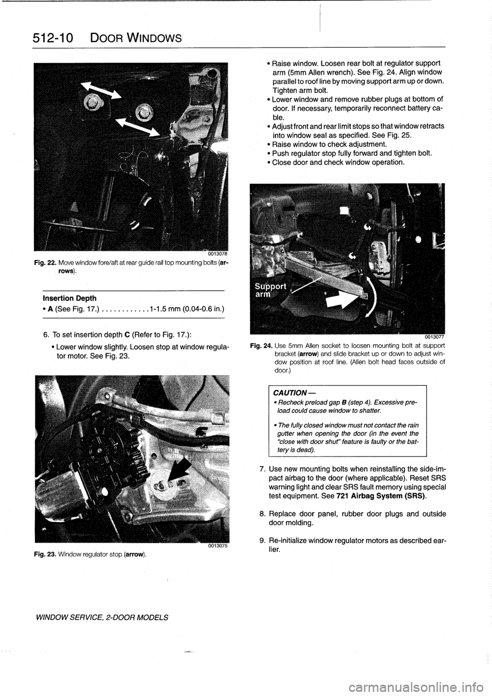
Fig
.
22
.
Move
window
fore/aftatrear
guide
rail
top
mounting
bolts
(ar-
rows)
.
Insertion
Depth
"
A
(See
Fig
.
17
.)
.
..........
.1-1
.5
mm
(0
.04-0
.6
in
.)
6
.
To
set
Insertion
depth
C
(Refer
to
Fig
.
17
.)
:
"
Lower
window
slightly
.
Loosen
stop
at
window
regula-
tor
motor
.
See
Fig
.
23
.
Fig
.
23
.
Window
regulator
stop
(arrow)
.
WINDOW
SERVICE,
2-DOOR
MODELS
0013075
"
Raise
window
.
Loosen
rear
boltat
regulator
support
arm
(5mm
Allen
wrench)
.
See
Fig
.
24
.
Align
window
parallelto
roof
line
by
moving
support
arm
up
or
clown
.
Tighten
arm
bolt
.
"
Lower
window
and
remove
rubber
plugs
at
bottom
of
door
.
If
necessary,temporarily
reconnect
battery
ca-
ble
.
"
Adjust
front
and
rear
limit
stops
so
that
window
retracts
into
window
seal
as
specified
.
See
Fig
.
25
.
"
Raise
window
to
check
adjustment
.
"
Push
regulator
stop
fully
forward
and
tighten
bolt
.
"
Closedoor
and
check
window
operation
.
0013077
Fig
.
24
.
Use
5mm
Afen
socket
to
loosen
mounting
boltat
support
bracket(arrow)
and
slide
bracket
up
or
clown
to
adjust
win-
dow
position
at
roof
line
.
(Allen
bolt
head
faces
outside
of
door
.)
CAUTION
-
"
Recheck
preload
gap
B
(step
4)
.
Excessive
pre-
load
could
cause
window
to
shatter
.
"
The
fully
closed
window
must
not
contact
the
rain
gutter
when
opening
the
door
(in
the
event
the
"close
with
door
shut"
feature
is
faulty
or
the
bat-tery
is
dead)
.
7
.
Usenew
mounting
bolts
when
reinstalling
the
side-im-
pact
airbag
to
the
door
(where
applicable)
.
Reset
SRS
warning
light
and
clear
SRS
fault
memory
using
special
test
equipment
.
See
721
Airbag
System
(SRS)
.
8
.
Replace
door
panel,
rubber
door
plugs
and
outside
doormolding
.
9
.
Re-initialize
window
regulator
motors
as
described
ear-
lier
.
Page 345 of 759
GENERAL
This
repair
group
covers
interior
trim
removal
and
installa-
tion
procedures
.
Forremoval
and
installation
of
interior
switches,
including
interior
lighting
equipment,
see
612
Switches
and
Electrical
Accessories
.
Most
of
the
interior
trim
and
finish
paneis
are
clipped
or
screwed
into
place
.
Many
of
the
trim
retaining
clips
arede-
signed
to
be
used
only
once
.
When
removing
trim
that
is
held
in
place
with
clips,
it
is
a
good
idea
lo
have
spareson
hand
be-
fore
beginningthejob
.
CENTER
CONSOLE
The
front
section
center
console
houses
the
Multi-Informa-
tion
Display
(MID)
module,the
front
ashtray
and
cigarette
lighter
;
shifter
lever,
power
window
switches
and
the
hazard
warning
switch
.
The
rear
center
console
section
houses
the
ashtray(s)
and
covers
the
emergency
brakecable
ends
.
Center
console,
removing
and
installing
1
.
Disconnect
negative
(-)
cable
from
battery
and
cover
terminal
with
insulating
material
.
CA
UTION-
Prior
to
disconnectiog
the
battery,
read
the
battery
disconnection
cautionsgiven
at
the
front
of
this
manual
onpage
viii
.
2
.
Remove
shifter
boot
or
selectorlever
cover
.
See250
Gearshift
t-inkage
.
3
.
Remove
rear
ashtray
retaining
screws
totake
out
ash-
tray
.
Remove
rear
console
retaining
screwunder
ash-
tray
.
513
Interior
Tri
m
INTERIORTRIM
513-1
GENERAL
..
.
.....
.
.
.
.
.
.
.
.
.
.
.
......
.
.
.
513-1
DASHBOARD
.....
.
.
.
.
.
.
.
.
.
.
.
.
.
.
...
.
:
.
.513-2
Glove
compartment,removing
and
installing
.
.513-2
CENTER
CONSOLE
.
.
.
.
.
.
.
.
.
.
.........
513-1
Lower
left
dash
panel,
Center
console,
removing
and
installing
.....
513-1
removing
and
installing
.
.
.
.
.
.
.
.
.
.
.....
.
.
513-2
Dashboard,removing
and
installing
.
.
.
.
...
.
.513-3
4
.
Remove
Multi-Information
Display
module
.
See620
In-
struments
.
5
.
Remove
hazardwarning
switch
and
power
window
switches
bypushing
up
and
out
from
below
.
6
.
Remove
lower
left
dashboard
panel
and
glove
compart-
ment
as
described
later
in
this
repair
group
.
7
.
Remove
retaining
screwunder
hazard
light
switch
.
Pull
rear
console
back
and
remove
retaining
nut
at
back
of
front
console
.
See
Fig
.
1
.
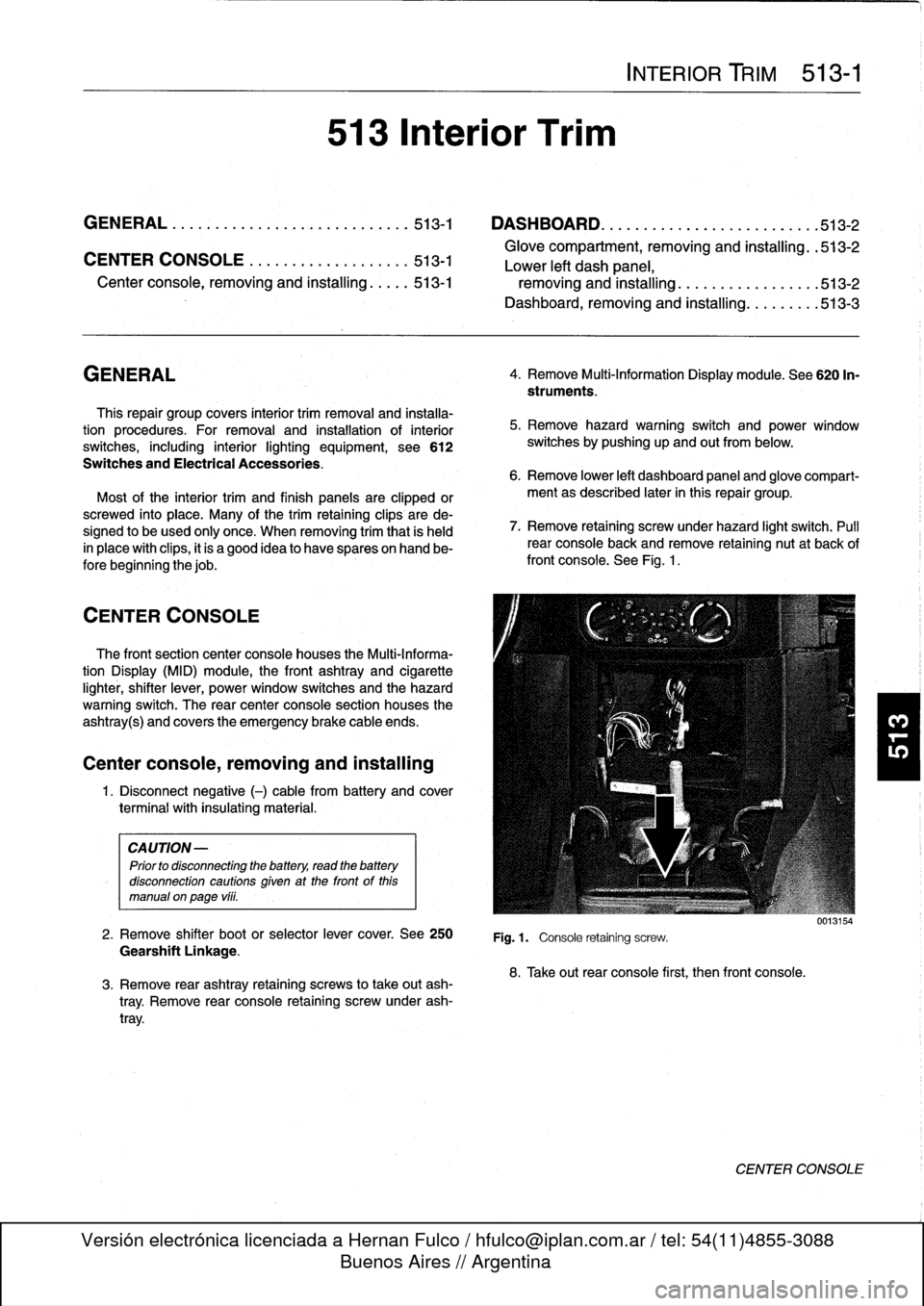
Fig
.1.
Console
retaining
screw
.
8
.
Take
out
rear
console
first,
then
front
console
.
0013154
CENTER
CONSOLE
Page 347 of 759
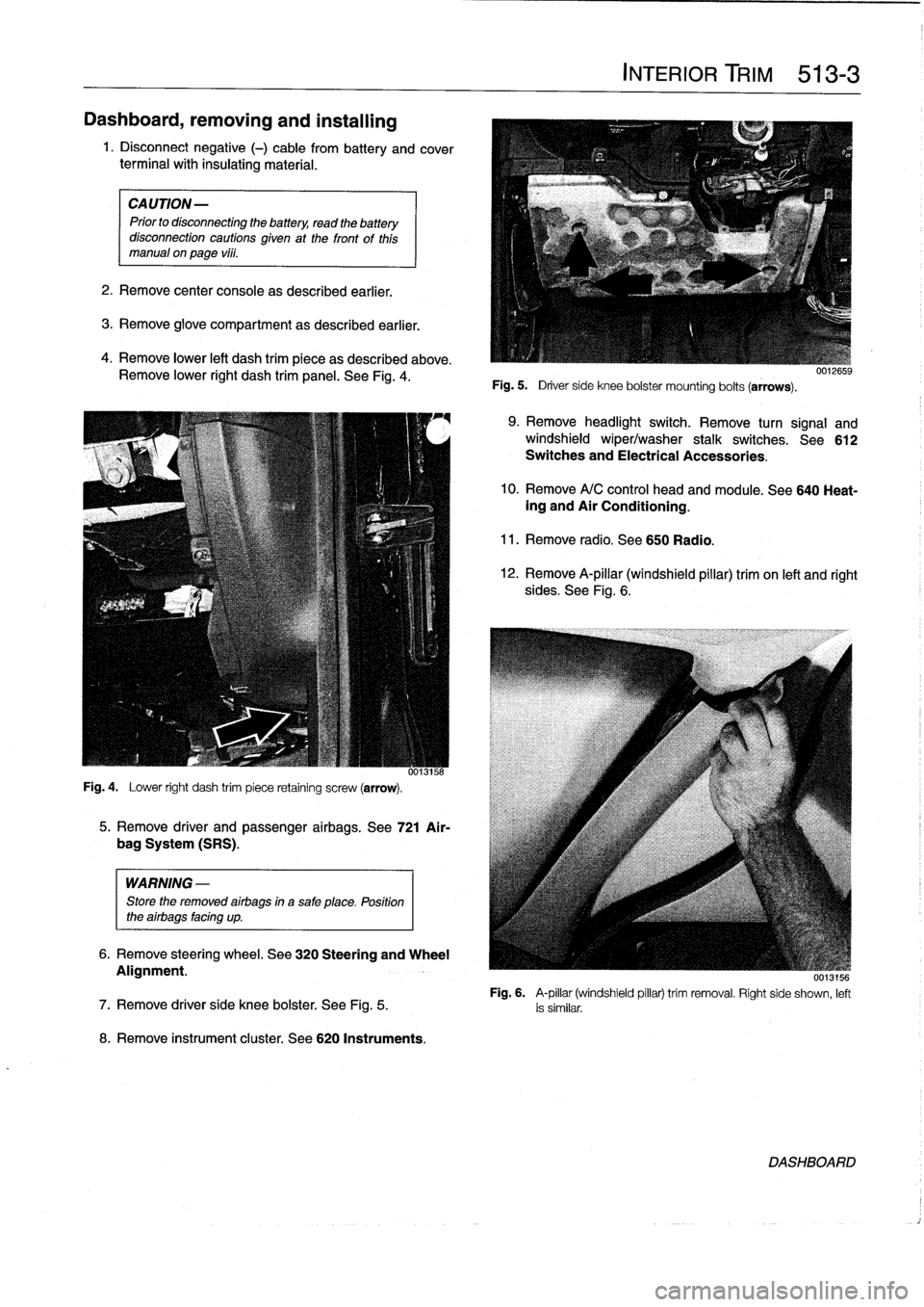
Dashboard,
removing
and
installing
1
.
Disconnect
negative
(-)
cable
from
battery
and
cover
terminal
with
insulating
material
.
CAUTION-
Prior
to
disconnectiog
the
battery,
read
the
battery
disconnection
cautionsgiven
at
the
front
of
this
manual
onpage
vi¡¡
.
2
.
Remove
center
console
as
described
earlier
.
3
.
Remove
glove
compartment
as
described
earlier
.
4
.
Remove
lower
left
dash
trim
piece
as
described
above
.
Remove
lower
right
dash
trim
panel
.
See
Fig
.
4
.
Fig
.
4
.
Lower
right
dash
trim
piece
retaining
screw
(arrow)
.
WARNING
-
Store
the
removed
airbags
in
a
safe
place
.
Position
the
airbags
facing
up
.
8
.
Remove
instrument
cluster
.
See
620
Instruments
.
5
.
Remove
driver
and
passenger
airbags
.
See
721
Air-
bag
System
(SRS)
.
6
.
Remove
steering
wheel
.
See
320
Steering
and
Wheel
Alignment
.
INTERIOR
TRIM
513-
3
Fig
.
5
.
Driver
side
knee
bolster
mounting
bolts
(arrows)
.
9
.
Remove
headlight
switch
.
Remove
turn
signal
and
windshield
wiper/washer
stalk
switches
.
See612
Switches
and
Electrical
Accessories
.
10
.
Remove
A/C
control
head
and
module
.
See
640
Heat-ing
and
Air
Conditioning
.
11
.
Remove
radio
.
See650
Radio
.
12
.
Remove
A-pillar
(windshield
pillar)
trim
on
left
and
right
sides
.
See
Fig
.
6
.
UU13156
Fig
.
6
.
A-pillar
(windshield
pillar)
trim
removal
.
Right
side
shown,
left
7
.
Remove
driver
side
knee
bolster
.
See
Fig
.
5
.
is
similar
.
DASHBOARD
Page 348 of 759
513-
4
INTERIOR
TRIM
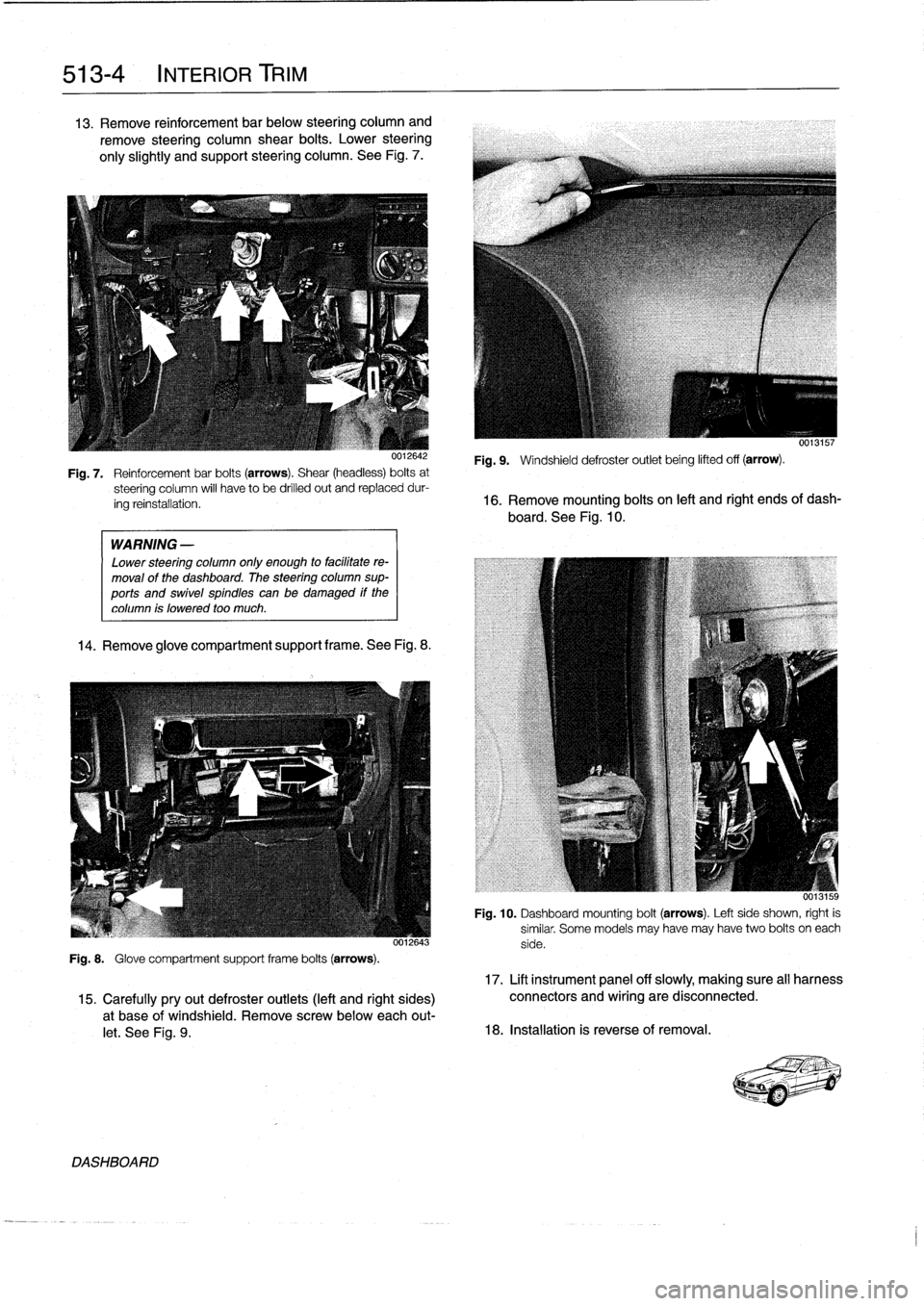
13
.
Remove
reinforcement
bar
below
steering
column
and
remove
steering
column
shear
bolts
.
Lower
steering
only
slightly
and
support
steering
column
.
See
Fig
.
7
.
WARNING
-
Lower
steering
column
only
enough
to
facilitate
re-
moval
of
the
dashboard
.
The
steering
column
sup-
ports
and
swivel
spindles
canbe
damaged
if
the
column
is
lowered
too
much
.
14
.
Remove
glove
compartment
support
frame
.See
Fig
.
8
.
0012643
Fig
.
8
.
Glove
compartment
support
frame
bolts
(arrows)
.
DASHBOARD
0013157
Fig
.
9
.
Windshield
defroster
outlet
being
lifted
off
(arrow)
.
Fig
.
7
.
Reinforcementbar
bolts
(arrows)
.
Shear
(headless)
bolts
at
steering
column
will
have
to
be
drilled
out
and
replaceddur-
ing
reinstallation
.
16
.
Remove
mounting
bolts
on
left
and
right
ends
of
dash-
board
.
See
Fig
.
10
.
Fig
.
10
.
Dashboard
mounting
bolt
(arrows)
.
Left
side
shown,
right
is
similar
.
Some
models
may
have
may
have
two
bolts
oneach
side
.
17
.
Lift
instrument
panel
off
slowly,
making
sure
all
harness
15
.
Carefullypryout
defroster
outlets
(left
and
right
sides)
connectors
and
wiring
are
disconnected
.
a
t
base
of
windshield
.
Remove
screwbelow
each
out-
let
.
See
Fig
.
9
.
18
.
Installation
is
reverse
of
removal
.
Page 351 of 759
![BMW M3 1992 E36 Repair Manual
Front
door
handle,
removing
and
installing
1
.
Closedoor
window
completely
.
2
.
Remove
front
door
panel
and
vapor
barrier
asde-
scribed
in
411
Doors
.
WARNING
-
Some
1997
and
al]
1998
cars
are
f BMW M3 1992 E36 Repair Manual
Front
door
handle,
removing
and
installing
1
.
Closedoor
window
completely
.
2
.
Remove
front
door
panel
and
vapor
barrier
asde-
scribed
in
411
Doors
.
WARNING
-
Some
1997
and
al]
1998
cars
are
f](/img/1/2800/w960_2800-350.png)
Front
door
handle,
removing
and
installing
1
.
Closedoor
window
completely
.
2
.
Remove
front
door
panel
and
vapor
barrier
asde-
scribed
in
411
Doors
.
WARNING
-
Some
1997
and
al]
1998
cars
are
fitted
with
side-im-
pact
airbags
in
the
front
doors
.
When
servicing
the
door
handles
on
cars
with
front
side-impact
airbags,
always
disconnect
the
negative
(-)
battery
terminal
.
See
721
Airbag
System
(SRS)
for
cautions
and
pro-
cedures
relatíng
to
the
airbag
system
.
3
.
On
carswíth
side-impact
airbags,
disconnect
negative
(-)
cable
from
battery,
then
remove
airbag
module
.
CAUTION-
Prior
to
disconnecting
the
battery,
read
the
battery
disconnection
cautions
given
at
the
front
of
thís
manual
onpage
vi¡¡
.
NOTE-
In
some
models
covered
inthis
manual,
it
is
not
essen-
tial
to
remove
the
side-impact
airbag
to
access
internal
door
components
.
However,
the
procedure
is
recom-
mended
for
safety
reasons
.
4
.
Remove
door
lock
as
described
earlier
.
5
.
Remove
window
as
described
in
512
Door
Windows
.
CA
UTION-
On
models
with
side-impact
airbags,
removinglin-
stalling
the
front
window
requires
that
the
battery
cable
bereconnected
wíth
the
side-impact
airbag
disconnected
.
This
will
seta
fault
code
in
the
SRS
control
module,
turn
on
the
SRS
warning
light,
and
disable
the
SRS
system
until
the
fault
memo-
ry
is
cleared
usíng
special
SRS
test
equipment
.
6
.
Pry
out
access
plug
in
end
of
door
.
Use
screwdriver
through
access
hole
to
slide
exteriortrim
locking
plate
into
released
position
.
See
Fig
.
5
.
Remove
doorhandle
exterior
trim
piece
.
7
.
Working
inside
door,
remove
locking
clip
for
doorhan-
dle
retaining
pin
and
push
pin
out
.
8
.
Working
inside
door,
disconnect
electrical
harness
con-
nector
at
door
handle
.
Twist
plastic
connector
bracket
to
remove
from
door
handle
.
CENTRAL
LOCKING
AND
ANTI-THEFT
515-
3
0011681
Fig
.
5
.
Insert
screwdriver
into
access
hole
and
push
lockingplate
forward
(arrow)
to
release
exterior
handle
trim
.
uu11682
Fig
.
6
.
Door
handle
retaining
pin(A)
and
lock
collar
nut
(B)
.
Door
handle
trim
shown
removed
.
10
.
Remove
door
handle
fromdoor
by
angling
out
of
door
cavity
.
Removed
door
handle
assembly
is
shown
in
Fig
.
7
.
0012684
Fig
.
7
.
Door
handle
harnessconnector
(A)
;
retaining
pin
Iocking
clip
9
.
Working
at
door
exterior,
remove
handle
collar
nut
(B)
;
exterior
trim
Iocking
plate
(C)
.
Handleassembly
shown
re-
while
supporting
handle
.
See
Fig
.
6
.
moved
from
door
.
DOOR
HANDLES
AND
LOCKS
Page 352 of 759
515-4
CENTRAL
LOCKING
AND
ANTI-THEFT
11
.
Installation
is
reverse
of
removal
.
Keep
in
mind
the
fol-
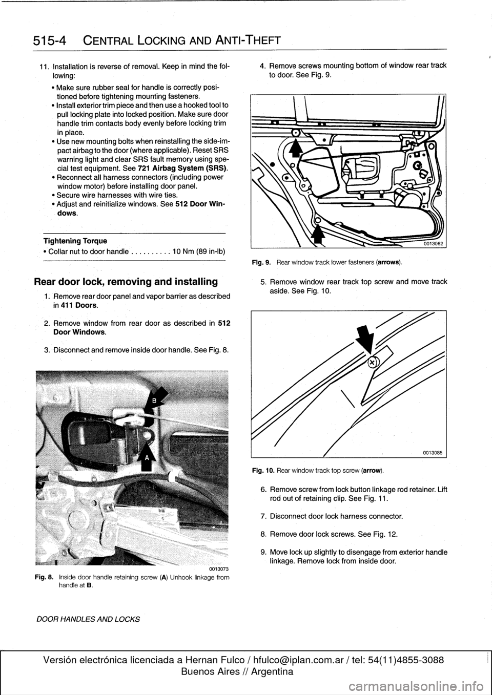
4
.
Remove
screws
mounting
bottom
of
window
rear
track
lowing
:
to
door
.
See
Fig
.
9
.
"
Make
sure
rubber
seal
for
handle
is
correctly
posi-
tionedbefore
tightening
mounting
fasteners
.
"
Install
exteriortrim
piece
and
then
use
a
hooked
tool
to
pull
locking
plate
into
locked
position
.
Make
sure
door
handle
trim
contacts
body
evenly
before
locking
trim
in
place
.
"
Use
new
mounting
bolts
when
reinstalling
the
side-im-
pactairbag
to
the
door(where
applicable)
.
Reset
SRS
warning
light
and
clear
SRS
fault
memory
using
spe-
cial
test
equipment
.
See
721
Airbag
System
(SRS)
.
"
Reconnect
al¡
harness
connectors
(including
power
window
motor)before
installing
door
panel
.
"
Secure
wire
harnesses
withwire
ties
.
"
Adjust
and
reinitialize
windows
.
See
512
Door
Win-
dows
.
Tightening
Torque
"
Collar
nut
to
doorhandle
..........
10
Nm
(89
in-lb)
1.
Remove
rear
door
panel
and
vapor
barrier
as
described
in
411
Doors
.
2
.
Remove
window
from
rear
dooras
described
in
512
Door
Windows
.
3
.
Disconnect
andremove
inside
door
handle
.
See
Fig
.
8
.
0013073
Fig
.
8
.
Inside
door
handle
retaining
screw
(A)
Unhook
linkage
from
handle
at
B
.
DOOR
HANDLES
AND
LOCKS
Fig
.
9
.
Rear
window
track
lower
fasteners
(arrows)
.
Reardoor
lock,
removing
and
installing
5
.
Remove
window
rear
track
top
screw
and
move
track
aside
.
See
Fig
.
10
.
Fig
.
10
.
Rear
window
track
top
screw
(arrow)
.
6
.
Remove
screw
from
lock
button
linkage
rod
retainer
.
Lift
rod
out
of
retaining
clip
.
See
Fig
.
11
.
7
.
Disconnect
door
lock
harnessconnector
.
8
.
Remove
door
lock
screws
.
See
Fig
.
12
.
0013085
9
.
Move
lock
upslightly
to
disengage
from
exterior
handle
linkage
.
Remove
lock
from
inside
door
.
Page 355 of 759
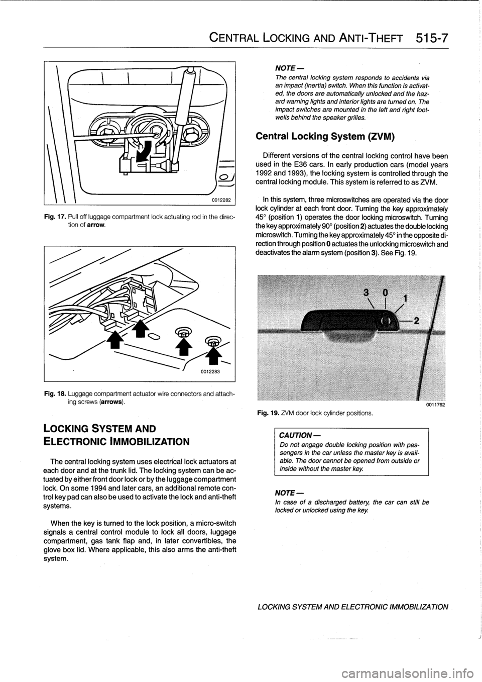
002262
In
this
system,
three
microswitches
are
operated
via
the
door
lock
cylinder
at
each
front
door
.
Turning
the
key
approximately
Fig
.
17
.
Pufl
off
luggage
compartment
lock
actuating
rod
in
the
direc-
45°
(position
1)
operates
the
door
locking
microswitch
.
Tuming
tionof
arrow
.
the
key
approximately
90°
(position2)
actuates
the
double
locking
microswitch
.
Tuming
the
key
approximately
45°
in
the
opposite
di-
rection
through
position
0
actuates
the
unlocking
microswitch
and
deactivates
the
alarm
system
(position3)
.
See
Fig
.
19
.
Fig
.
18
.
Luggage
compartment
actuatorwire
connectors
and
attach-
ing
screws
(arrows)
.
LOCKING
SYSTEM
AND
ELECTRONIC
IMMOBILIZATION
The
central
locking
system
uses
electrical
lock
actuators
at
each
door
and
at
the
trunk
lid
.
The
locking
system
can
be
ac-
tuated
by
either
front
door
lock
or
by
the
luggage
compartment
lock
.
Onsome
1994
and
later
cars,
an
additional
remote
con-
trol
keypadcan
also
be
used
to
activate
the
lock
and
anti-theft
systems
.
When
the
key
is
tuned
to
the
lock
position,
a
micro-switch
signals
a
central
control
module
to
lock
all
doors,
luggage
compartment,
gas
tank
flap
and,
in
later
convertibles,
the
glove
box
lid
.
Where
applicable,
this
also
arms
the
anti-theft
system
.
CENTRAL
LOCKING
AND
ANTI-THEFT
515-7
NOTE-
The
central
locking
system
responds
to
accidents
vía
animpact
(inertia)
switch
.
When
this
function
ís
activat-
ed,
the
doors
are
automatically
unlocked
and
the
haz-
ard
warning
lights
and
interiorlights
are
turned
on
.
The
impact
switches
are
mounted
in
the
left
and
right
foot-
wells
behind
the
speaker
grilles
.
Central
Locking
System
(ZVM)
Different
versions
of
the
central
locking
control
havebeen
used
in
the
E36
cars
.
In
early
production
cars
(model
years
1992
and
1993),
the
locking
system
is
controlled
through
the
central
locking
module
.
This
system
is
referred
to
as
ZVM
.
Fig
.
19
.
ZVM
door
lock
cylinderpositíons
.
CAUTION-
Do
not
engage
double
locking
position
with
pas-
sengers
in
the
car
unless
the
master
key
isavail-
able
.
The
door
cannotbe
opened
from
outside
orinside
without
the
master
key
.
NOTE-
In
case
of
a
discharged
battery,
the
car
can
still
be
locked
orunlocked
using
the
key
.
0011762
LOCKING
SYSTEM
AND
ELECTRONIC
IMMOBILIZATION
Page 379 of 759
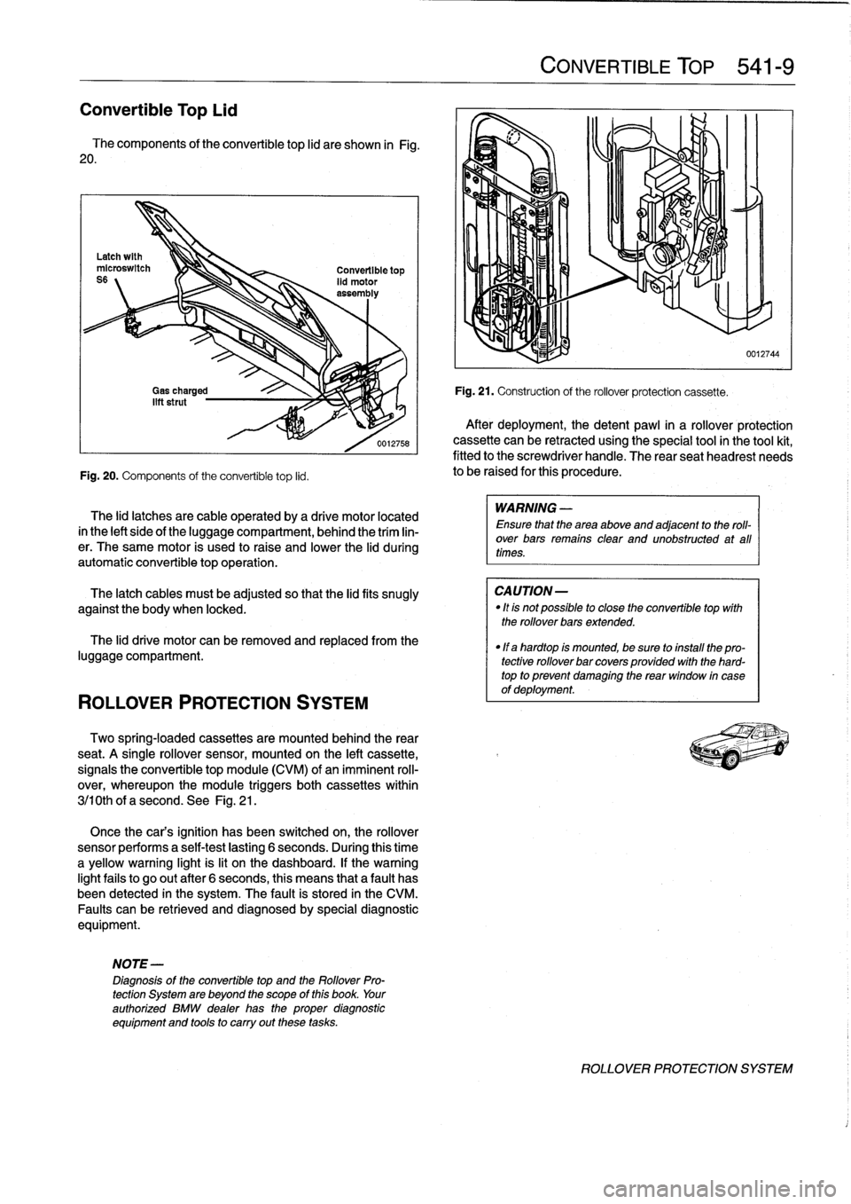
Convertible
Top
Lid
The
components
of
the
convertible
top
lid
are
shown
in
Fig
.
20
.
Fig
.
20
.
Components
of
the
convertible
top
lid
.
ROLLOVER
PROTECTION
SYSTEM
The
lid
latches
are
cable
operated
by
a
drive
motor
located
in
the
left
sideof
the
luggagecompartment,
behind
the
trim
lin-
er
.
The
same
motor
is
used
to
raise
and
lower
the
lid
during
automatic
convertible
topoperation
.
The
latch
cables
must
be
adjusted
so
that
the
lidfits
snugly
against
the
body
when
locked
.
The
lid
drive
motor
can
be
removed
and
replaced
from
the
luggage
compartment
.
Two
spring-locaed
cassettes
are
mounted
behind
the
rear
seat
.
A
single
rollover
sensor,
mounted
on
the
left
cassette,
signals
the
convertible
top
module
(CVM)
of
animminent
roll-
over,
whereupon
the
module
triggers
both
cassettes
within
3j10th
of
a
second
.
See
Fig
.
21
.
Once
the
cars
ignition
has
been
switched
on,
the
rollover
sensor
performs
a
self-test
lasting
6
seconds
.
During
this
time
a
yellow
warning
light
is
lit
on
the
dashboard
.
If
thewarning
lightfails
to
go
out
after
6
seconds,
this
means
that
a
fault
has
been
detected
in
the
system
.
The
fault
is
stored
in
the
CM
Faults
canbe
retrieved
and
diagnosedby
special
diagnostic
equipment
.
NOTE-
Diagnosis
of
the
convertible
top
and
the
Rollover
Pro-
tection
System
are
beyond
the
scope
of
this
book
.
Your
authorized
BMW
dealer
has
the
proper
diagnostic
equipment
and
tools
to
carry
out
these
tasks
.
CONVERTIBLE
TOP
541-
9
Fig
.
21
.
Construction
of
the
rollover
protection
cassette
.
After
deployment,
thedetent
pawl
in
a
rollover
protection
cassette
can
be
retracted
using
the
special
tool
in
the
tool
kit,
fitted
to
the
screwdriver
handle
.
The
rear
seatheadrest
needs
to
be
raised
for
this
procedure
.
WARNING
-
Ensure
that
the
area
above
and
adjacent
to
the
roll-
over
bars
remains
clear
and
unobstructed
at
all
times
.
CAUTION-
"
Itis
not
possible
to
close
the
convertible
top
with
the
rollover
bars
extended
.
"
If
a
hardtop
is
mounted,
be
sure
to
install
the
pro-
tective
rollover
bar
covers
provided
with
the
hard-
top
to
prevent
damaglng
the
rear
window
in
case
of
deployment
.
0012744
ROLLOVER
PROTECTION
SYSTEM