indicator BMW M3 1993 E36 User Guide
[x] Cancel search | Manufacturer: BMW, Model Year: 1993, Model line: M3, Model: BMW M3 1993 E36Pages: 759
Page 174 of 759
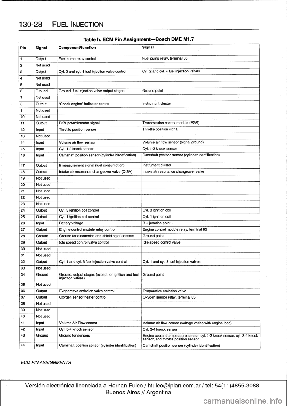
130-
2
8
FUEL
INJECTION
Tableh
.
ECM
Pin
Assignment-Bosch
DME
M1
.7
Pin
Signal
Componenttfunction
Signal
1
Output
Fuel
pump
relay
control
Fuel
pump
relay,
terminal
85
2
Not
used
3
Output
Cyl
.
2
and
cyl
.
4
fuel
injection
valve
control
Cyl
.
2
and
cyl
.
4
fuel
injection
valves
4
Not
used
5
Not
used
6
Ground
Ground,
fuel
injection
valveoutputstages
Ground
point
7
Not
used
8
Output
"Check
engine"
indicator
control
Instrument
cluster
9
Not
used
10
Not
used
11
Output
DKV
potentiometer
signal
Transmission
control
module
(EGS)
12
Input
Throttleposition
sensor
Throttleposition
Signal
13
Not
used
14
Input
Volume
air
flow
sensor
Volume
air
flow
sensor
(signal
ground)
15
Input
Cyl
.
1-2
knock
sensor
Cyl
.
1-2
knock
sensor
16
Input
Camshaft
position
sensor
(cylinder
identification)
Camshaft
position
sensor
(cylinder
identification)
17
Output
ti
measurement
signal
(fuel
consumption)
Instrument
cluster
18
Output
Intakeair
resonance
changeover
valve
(DISA)
Intake
air
resonance
changeover
valve
19
-
Not
used
20
Not
used
21
Not
used
22
Not
used
23
Not
used
24
Output
Cyl
.
3
ignition
coil
control
Cyl
.
3
ignition
coil
25
Output
Cyl
.
1
ignition
coil
control
Cyl
.
1
ignition
coil
26
Input
Battery
voltage
B
+junction
point
27
Output
Engine
control
module
relay
control
Engine
control
module
relay,
terminal
85
28
Ground
Ground
for
electronics
and
shielding
of
sensors
Ground
point
29
Output
Idle
speed
control
valve
control
Idle
speed
control
valve
30
Not
used
31
Not
used
32
Output
Cyl
.
1
and
cyl
.
3
fuel
injection
valve
control
Cyl
.
1
and
cyl
.
3
fuel
injection
valves
33
Not
used
34
Ground
Ground,
output
stages
(except
for
ignition
and
fuel
Ground
point
injection
valves)
35
Not
used
36
Output
Evaporative
emissionvalve
control
Evaporative
emission
valve
37
Output
Oxygen
sensor
heater
control
Oxygen
sensor
relay,
terminal
85
38
Not
used
39
Not
used
40
I
Not
used
41
I
Input
,
Volume
Air
Flow
sensor
Volume
air
flow
sensor
(voltage
varies
with
engine
load)
42
1
Input
1
Cyl
.
3-4
knock
sensor
1
Cyl
.
3-4
knock
sensor
43
Ground
Ground
for
sensors
Engine
coolant
temperature
sensor,
cyl
.
1-2
knock
sensor,
cyl
.
3-4
knock
sensor,
and
throttle
position
sensor
44
1
Input
1
Camshaft
position
sensor
(cylinder
identification)
1
Camshaft
position
sensor
(cylinder
identification)
ECM
PIN
ASSIGNMENTS
Page 229 of 759
AUTOMATIC
TRANSMISSION
240-1
240
Automatic
Transmission
GENERAL
.....
.
.
.
.
.
.
.
.
.
.
.
.
.
.........
.
240-1
TRANSMISSION
REMOVAL
AND
INSTALLATION
..................
.
.
.
.
.240-4
TRANSMISSION
SERVICE
.
.
.
.
.
.......
.
240-1
Transmission,
removing
and
installing
....
.
.
.240-4
ATF
leve¡,
checking
..
.
.
.
.
.
.
.
.
.
..........
240-1
ATF,
draining
and
filling
.
.
.
.
.
.
.
..........
240-2
TABLE
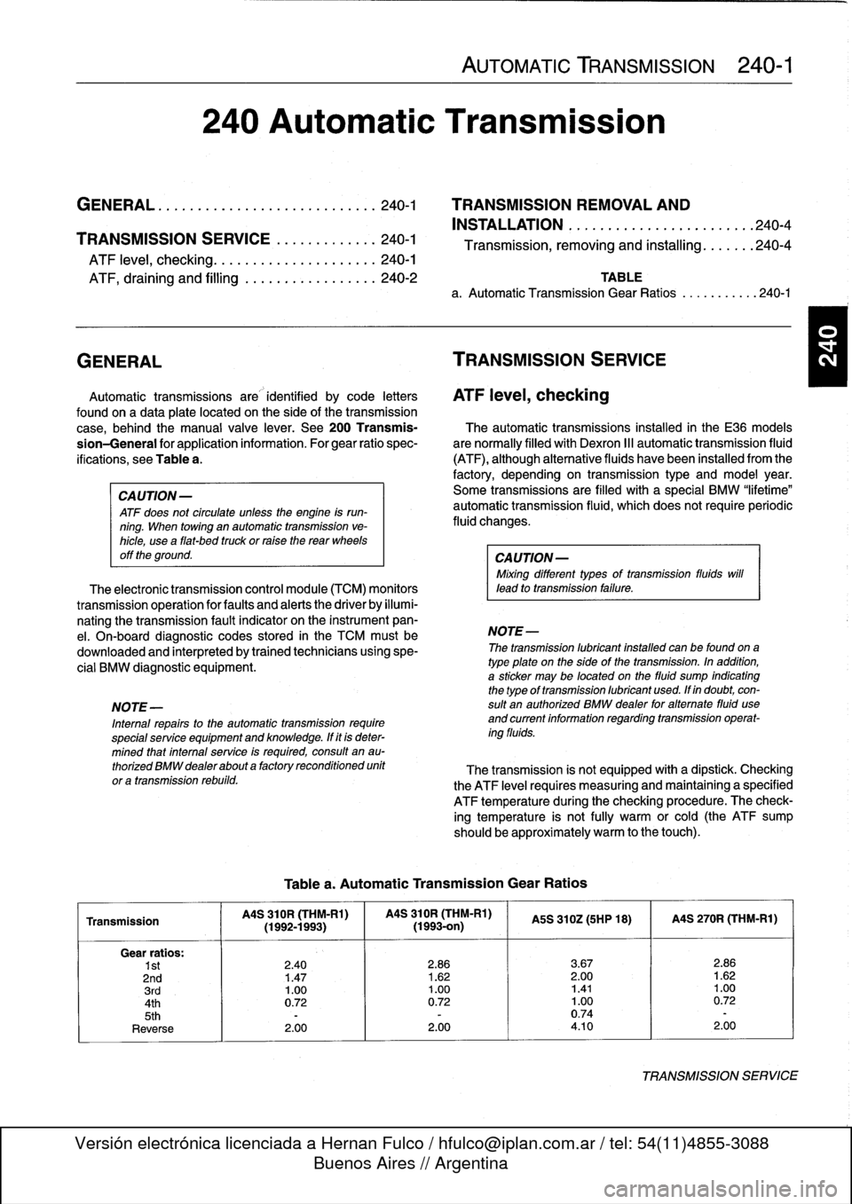
a
.
Automatic
Transmission
Gear
Ratios
.......
..
.
.
240-1
GENERAL
TRANSMISSION
SERVICE
lo
Automatic
transmissions
are
identified
by
code
letters
ATF
leve¡,
checking
foundon
a
data
plate
located
on
the
sideof
thetransmission
case,
behind
the
manual
valve
lever
.
See
200Transmis-
The
automatic
transmissions
installed
in
the
E36
models
sion-General
for
application
information
.
Forgear
ratio
spec-
are
normally
filled
with
Dexron
III
automatic
transmission
fluid
ifications,
see
Table
a
.
(ATF),
although
alternative
fluids
have
been
installed
from
the
factory,
depending
on
transmission
type
and
model
year
.
CAUTION-
Some
transmíssions
are
filled
with
a
special
BMW
"lifetime"
ATF
does
not
circulate
unless
the
engine
is
run-
automatic
transmission
fluid,
which
does
not
require
periodic
ning
.
When
towing
an
automafic
transmission
ve-
fluid
changes
.
hicle,
usea
flat-bed
truck
or
ralse
the
rear
wheels
off
the
ground
.
CAUTION-
Mixing
different
types
of
transmission
fluids
will
The
electronic
transmission
control
module
(TCM)
monitors
lead
to
transmission
failure
.
transmissionoperation
for
faults
and
alerts
the
driver
by
illumi-
nating
the
transmission
fault
indicator
on
the
instrument
pan-
el
.
On-board
diagnostic
codes
stored
in
the
TCM
mustbe
NOTE-
downloaded
and
interpreted
by
trained
technicians
using
spe-
The
transmission
lubricant
instafed
can
be
foundona
cial
BMW
diagnostic
equipment
.
type
plate
on
the
side
of
the
transmission
.
In
addition,
a
sticker
may
be
located
on
the
fluid
sump
indicatingthe
typeof
transmission
lubricant
used
.
Ifin
doubt,
con
NOTE-
sult
an
authorized
BMW
dealer
for
altemate
fluid
use
Internal
repairs
to
the
automatic
transmission
require
and
current
information
regardingtransmission
operat-
special
service
equipment
and
knowledge
.
If
it
is
deter-
ing
fluids
.
mined
thatinterna¡
service
is
required,
consult
en
au-
thorízedBMWdealerabouta
factoryreconditioned
unit
The
transmission
is
not
equipped
with
a
dipstick
.
Checking
or
a
transmission
rebuild
.
the
ATF
leve¡
requires
measuring
and
maintaining
a
specified
ATF
temperature
during
the
checking
procedure
.
The
check-
ing
temperature
is
not
fully
warm
orcold
(the
ATF
sump
should
be
approximately
warm
to
the
touch)
.
Table
a
.
Automatic
Transmission
Gear
Ratios
Transmission
MS
310R
(THM-R1)
MS
310R
(THM-Rl)
MS
310Z(5HP
18)
I
MS
270R
(THM-R1)
(1992-1993)(1993-on)
Gear
ratios
:
1st
2
.40
2
.86
3
.67
2
.86
2nd
1
.47
1
.62
2
.00
1
.62
3rd
1
.00
1
.00
1.41
1
.00
4th
0
.72
0
.72
1
.00
0
.72
5th
-
-
0
.74
-
Reverse
2
.00
2
.00
4
.10
2
.00
TRANSMISSIONSERVICE
Page 249 of 759
SUSPENSION,
STEERING
ANDBRAKES-GENERAL
300-1
300
Suspension,
Steering
and
Brakes-General
GENERAL
.....
.
....
.
.....
.
.
.
........
.300-1
M3
SUSPENSION
AND
BRAKES
.......
.
...
300-7
Front
Suspension
..........
.
.
.
...
.
.....
300-1
Steering
...
.
.
.
.
.
....
.
.
.
...
.
.
.
...
.
...
.
.
300-2
SUSPENSION
AND
STEERING
Rear
Suspension
....
.
.
.
...
.
.
.
...
.
.....
300-2
TROUBLESHOOTING
..
.
.
.
.............
300-7
Brakes
.
.
.
.
.
.
.
.
....
.
...........
.
.
.
.
.
.
300-2
Tires
and
wheeis
.
................
.
.
.
.
.
.
300-2
TABLE
a
.
AST
Indicator
Lamp
Function
..
..
.
..
.
.........
300-5
INTEGRATED
SYSTEMS
.........
.
.
.
.
.
.
300-2
b
.
Suspension
and
Steering
Troubleshooting
......
.300-8
Antilock
Brake
System
(ABS)
.......
.
.
.
.
.
.
300-2
Al¡
Season
Traction
(AST)
.........
.
.
.
.
.
.
300-4
GENERAL
Front
Suspension
This
section
covers
general
information
for
front
and
rear
The
lower
control
arms
connect
the
front
suspension
struts
suspension,
the
steering
system,
and
the
brakíng
and
traction
to
mounting
points
on
the
subframe
crossmember
and
the
control
systems
.
body
.
See
Fig
.
2
.
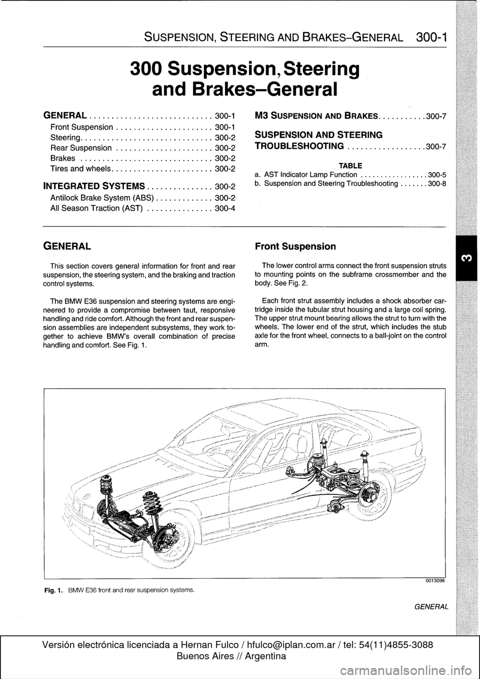
The
BMW
E36
suspension
and
steering
systems
are
engi-
neered
to
provide
a
compromise
between
taut,
responsive
handling
and
ride
comfort
.
Although
the
front
and
rear
suspen-
sion
assemblies
are
independent
subsystems,
they
work
to-
gether
to
achieve
BMW's
overall
combination
of
precise
handling
and
comfort
.
See
Fig
.
1
.
Fig
.
1
.
BMW
E36
front
and
rear
suspension
systems
.
Each
front
strut
assembly
includes
a
shock
absorber
car-
tridgeinside
the
tubular
strut
housing
and
a
large
coil
spring
.
The
upper
strut
mount
bearing
allows
the
strutto
turnwith
the
wheels
.
The
lower
end
of
the
strut,
which
includes
the
stub
axle
for
the
front
wheel,
connects
to
a
ball-joint
on
the
control
arm
.
0013098
GENERAL
Page 253 of 759
NOTE-
The
traction
control
system
referred
to
as
AST
(all
sea-
son
traction)
may
also
be
referred
to
as
ASC
(Automat-
ic
Stability
Control)
and
ASC+T
(Automatic
Stability
Control+Traction)
.
The
AST
system
improves
traction
by
electronically
apply-
ing
the
rear
brakes
when
therear
drive
wheels
are
spinning
at
a
faster
rate
than
the
front
wheels
.
The
combined
ABS/AST
control
module,
operating
through
the
ABS
hydraulic
control
unit,
modulates
braking
force
at
therear
wheels
.
In
addition,
AST
uses
retarded
ignition
timing
and
an
auxil-iary
engine
throttle
plate
to
reduceengine
torque
and
maintain
vehicle
stability
.
The
auxiliary
throttle
plate
is
held
open
by
spring
pressure
.
The
AST
system
actívates
the
auxiliary
throttie
position
motor
(ADS)
to
cose
the
AST
throttle
as
needed
.
This
reduces
the
volume
of
engine
intake
air
.
Due
to
the
throttle
closing
very
rapidly
during
AST
operationthe
driver
cannot
increase
theengine
power
output
regardless
of
how
far
theaccelerator
pedal
is
pushed
to
the
floor
.
The
auxiliary
throttle
plate
is
placed
ahead
of
the
conven-
tional
throttle
plate
in
the
throttle
body
.
Traction
control
also
comes
into
operationduringdecelera-
tion
.
Decelerating
on
snowy
or
icy
road
surfaces
can
lead
to
rear
wheel
slip
.
If
a
rear
wheel
startsto
drag
or
lock
up
when
the
throttle
is
closed
rapidly
orduringdownshifting,the
AST
system
can
limit
the
problem
by
advancing
the
ignition
timing
.
A
switch
on
the
center
console
is
used
to
togglethe
AST
on
or
off
.
The
AST
system
is
designed
to
be
maintenance
free
.
There
are
no
adjustments
that
can
be
made
.
Repair
and
trouble-
shooting
of
the
AST
system
requires
special
test
equipment
andknowledgeand
should
be
performed
only
by
an
autho-
rized
BMW
dealer
.
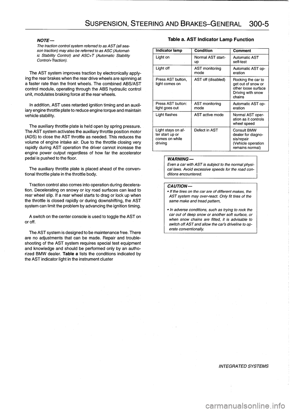
Table
a
lists
theconditions
indicated
by
the
AST
indicator
light
in
the
instrument
cluster
SUSPENSION,
STEERING
AND
BRAKES-GENERAL
300-5
Tablea
.
AST
Indicator
Lamp
Function
Indicator
lamp
1
Condition
1
Comment
Light
on
Normal
AST
start-
Automatic
AST
up
self-test
Light
off
AST
monitoring
Automatic
AST
op-
mode
eration
Press
AST
button,
AST
off
(disabled)
Rocking
the
car
tolight
comes
on
getout
of
snow
or
other
loose
surface
Driving
with
snow
chains
Press
AST
button
:
AST
monitoring
Automatic
AST
op-
light
goes
out
I
mode
eration
Light
flashes
AST
active
mode
I
Normal
AST
oper-
ation
as
it
controls
wheel
speed
Light
stays
on
af-
Defect
in
AST
Consult
BMW
ter
start
up
or
dealer
for
diagno-
comes
on
while
sis/repair
driving
(Vehicle
operation
remains
normal)
WARNING
-
Even
a
car
with
AST
is
subject
to
the
normal
physi-
cal
laws
.
Avoid
excessive
speeds
for
the
road
con-
ditions
encountered
.
CAUTION-
"
If
the
tires
on
the
carare
of
different
makes,
the
AST
system
may
over-react
.
Only
fit
tires
of
the
same
make
and
tread
pattem,
"In
adverse
conditions,
such
as
trying
to
rock
the
car
outof
deep
snow
or
another
soft
surface,
or
when
snow
chainsare
fitted,
it
is
advisable
to
switch
off
AST
and
allow
the
cars
driveline
to
op-
erate
conventionally
.
INTEGRATED
SYSTEMS
Page 254 of 759
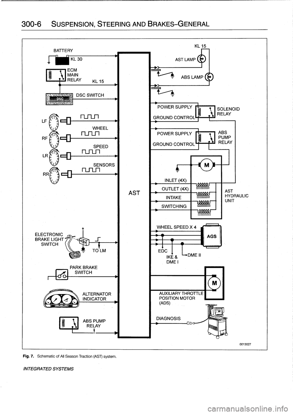
300-6
SUSPENSION,
STEERING
AND
BRAKES-GENERAL
BATTE
RY
KL
30
ECM
MAIN
C~
RELAY
KL
15
DSC
SWITCH
LF1
;1~lZZ~
nSLn
l'
z
sJ
WHEEL
RF
c_
.
LR
r_
.
>
RR
ELECTRONIC
BRAKE
LIGHT
SWITCH
SPEED
SENSORS
Fig
.
7
.
Schematic
of
AII
Season
Traction
(AST)
system
.
INTEGRATED
SYSTEMS
EDC
POWER
SUPPLY
SOLENOID
RELAY
GROUND
CONTROL
POWER
SUPPLY
I'
1
ABS
PUMP
GROUND
CONTROLÍ
F
f
iJ
RELAY
INLET
(4X)
wxxuw
OUTLET
(4X)
-=-=--
AST
AST
INTAKE
IHYDRAULIC
-
=-
SWITCHING
=---
!
99001
!J
WHEEL
SPEED
X
4
DME
II
000001
-
f
1
UNIT
AGS
IKE
&
DMEI
PARK
BREVE
771
SWITCH
M
ALTERNATOR
AUXILIARY
THROTTLE
r
`
INDICATOR
POSITION
MOTOR
(ADS)
ABSPUMP
DIAGNOSIS
RELAY
lu~~~b
0013027
Page 295 of 759
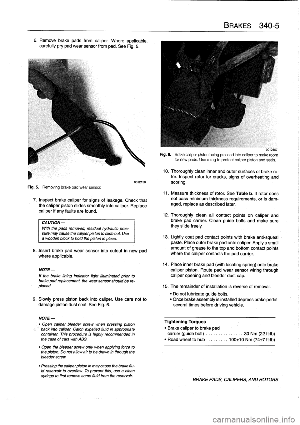
6
.
Remove
brake
pads
from
caliper
.
Where
applicable,
carefully
pry
pad
wear
sensor
from
pad
.
See
Fig
.
5
.
Fig
.
5
.
Removing
brake
pad
wear
sensor
.
7
.
Inspect
brake
caliper
for
signs
of
leakage
.
Check
that
the
caliper
piston
slides
smoothly
into
caliper
.
Replace
caliper
if
any
faults
are
found
.
CAUTION-
With
the
pads
removed,
residual
hydreulic
pres-
sure
may
cause
the
caliper
piston
to
slide
out
.
Use
a
wooden
block
to
hold
the
piston
in
place
.
8
.
fnsert
brake
pad
wear
sensor
into
cutout
in
new
pad
where
applicable
.
14
.
Place
inner
brake
pad
(with
locating
spring)
ontobrake
NOTE-
caliper
piston
.
Route
pad
wear
sensor
wiring
through
lf
the
brake
lining
indicator
light
illuminated
prior
to
caliper
opening
and
bleeder
dust
cap
.
brake
pad
replacement,
the
wear
sensor
should
be
re-
placed
.
15
.
The
remainder
of
installation
is
reverse
of
removal
.
"
Do
not
lubricate
guide
boits
.
9
.
Slowly
press
piston
back
into
caliper
.
Use
cace
not
to
"
Once
brake
assembly
is
installed
depress
brakepedal
damage
piston
dust
sea¡
.
See
Fig
.
6
.
severa¡
times
before
driving
vehicle
.
NOTE-
"
Open
caliper
bleeder
screw
when
pressing
piston
Tightening
Torques
back
into
caliper
.
Catch
expelled
fluidin
appropriate
"
Brake
caliper
to
brake
pad
container
.
This
procedure
is
highly
recommended
in
carrier
(guide
bolt)
..........
...
.
.
30
Nm
(22
ft-Ib)
the
case
of
cars
with
ABS
.
"
Road
wheel
to
hub
.....
.
..
100±10
Nm
(74±7
ft-Ib)
"
Open
the
bleeder
screw
only
when
applying
force
to
the
piston
.
Do
not
allow
airto
be
drawn
in
through
the
bleeder
screw
.
"
Pressing
the
caliper
piston
in
may
cause
the
brake
flu-
id
reservoir
to
overflow
.
To
prevent
this,
use
a
clean
syringe
to
first
remove
some
fluid
from
the
reservoir
.
BRAKES
340-
5
0012157
Fig
.
6
.
Brake
caliper
piston
being
pressed
into
caliper
to
make
room
for
new
pads
.
Usea
rag
toprotect
caliper
piston
and
seals
.
10
.
Thoroughly
clean
inner
and
outer
surfaces
of
brake
ro-
tor
.
Inspect
rotor
for
cracks,
signs
of
overheating
and
0012156
scoring
.
11
.
Measure
thickness
of
rotor
.
See
Table
b
.
If
rotor
does
not
pass
minimum
thickness
requirements,
or
is
dam-
aged,
replace
as
described
later
.
12
.
Thoroughly
clean
all
contact
points
on
caliper
and
brake
pad
carrier
.
Clean
guide
bolts
and
make
surethey
slide
freely
13
.
Lightly
coat
pad
contact
points
with
brake
anti-squeal
paste
.
Place
outer
brake
pad
onto
caliper
.
Applya
small
amount
of
grease
to
thetop
and
bottom
contact
points
where
the
caliper
contacts
the
pad
carrier
.
BRAKE
PADS,CALIPERS,
ANDROTORS
Page 306 of 759
400-
4
BODY-GENERAL
INTERIOR
EQUIPMENT
E36
interiors
have
a
unique
character,
with
a
combínation
of
sporty
features
and
innovative
design
.
Al¡
body
versions
were
made
in
a
wide
choice
of
interior
and
exterior
colors
.
New
colors
with
matching
leather
and/or
fabric
upholstery
were
in-
troduced
for
each
model
year,
including
light-alloy
wheels
in
new
designs
.
Driving
comfort
is
enhanced
by
power
steering,
tilt
steering
wheel
(optional),
height-adjustable
front
seats,
and
electrical-
ly
adjustable
and
heated
rear-view
mirrors
.
Inside
thecar
there
are
reading
lights
at
four
seating
positions
.
Seats
and
Seat
Belts
NOTE-
Theseat
base
usedon
cars
with
pyrotechnic
seatbelt
Anatom¡cal
ly-correct
seats
are
constructed
from
polyure-
tensioners
is
not
interchangeable
with
the
earlier
seat
thane
foam
containing
areas
or
"zones"
of
different
firmness
.
base
.
The
seat
bases
have
steel
springs
for
added
support
and
strength
.
The
power
seats
are
provided
with
conveniently
lo-
Instruments
and
Controls
cated
switches
along
the
outside
edge
of
the
seat
.
Heated
seats
are
an
option
in
all
models
.
See
520
Seats
for
more
de-
Everything
in
the
interior
passenger
compartment
essential
tails
.
to
the
driver
is
logically
grouped
and
easy
to
reach
.
Al¡
instru-
ments
and
controls
havebeen
arranged
ergonomically
and
The
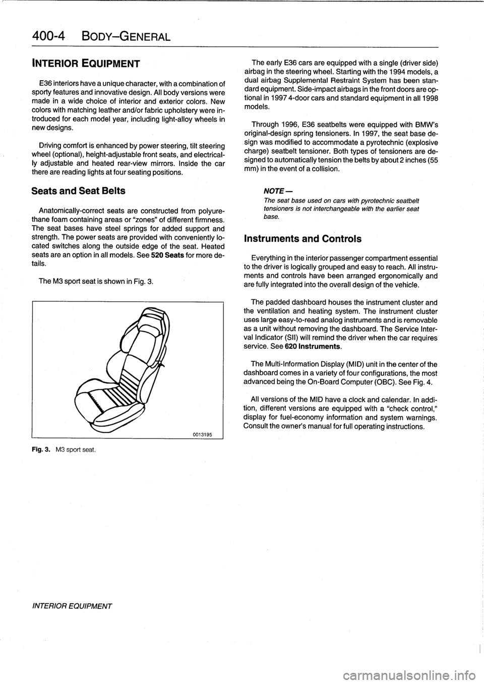
M3
sport
seat
is
shown
in
Fig
.
3
.
are
fully
integrated
into
the
overall
design
of
the
vehicle
.
Fig
.
3
.
M3
sport
seat
.
INTERIOR
EQUIPMENT
0013195
The
early
E36
cars
areequipped
with
a
single
(driver
side)
airbag
in
the
steering
wheel
.
Startingwith
the
1994
models,
a
dual
airbag
Supplemental
Restraint
System
has
been
stan-
dard
equipment
.
Side-impact
airbags
in
the
front
doors
are
op-
tional
in
1997
4-door
cars
and
standard
equipment
in
all
1998
models
.
Through
1996,
E36
seatbelts
were
equipped
with
BMW's
original-designspring
tensioners
.
In
1997,
the
seat
base
de-
sign
was
modified
to
accommodate
a
pyrotechnic
(explosive
charge)
seatbelt
tensioner
.
Both
types
of
tensioners
arede-
signed
to
automatically
tension
the
belts
by
about2
inches(55
mm)
in
the
event
of
a
collision
.
The
padded
dashboard
houses
the
instrument
cluster
and
the
ventilation
and
heating
system
.
The
instrument
cluster
uses
large
easy-to-read
analog
instruments
and
is
removable
as
a
unit
without
removing
the
dashboard
.
The
Service
Inter-
val
Indicator
(SII)
will
remind
the
driver
when
thecar
requires
service
.
See
620
Instruments
.
The
Multi-Information
Display
(MID)
unit
in
thecenter
of
the
dashboard
comes
in
a
variety
of
four
configurations,
the
most
advanced
being
the
On-Board
Computer
(OBC)
.
See
Fig
.
4
.
Al¡
versions
of
the
MID
have
a
clock
and
calendar
.
In
addi-
tion,
different
versions
areequipped
with
a
"check
control,"
display
for
fuel-economy
information
and
system
warnings
.
Consult
the
owner's
manual
for
fui¡
operating
instructions
.
Page 430 of 759
612-2
SWITCHES
AND
ELECTRICAL
ACCESSORIES
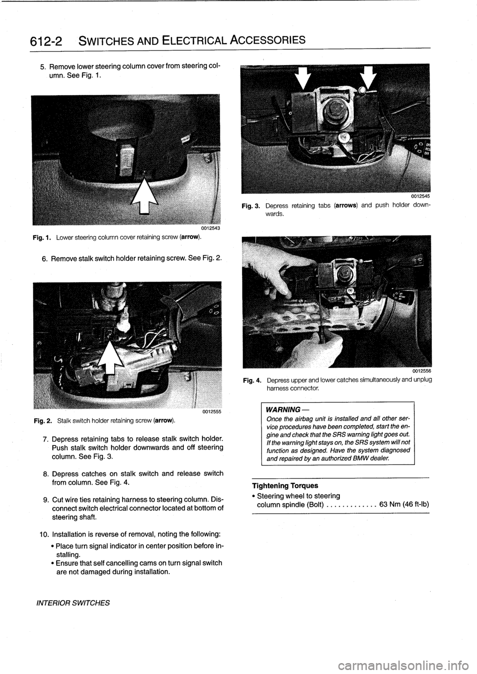
5
.
Remove
lower
steering
column
cover
from
steering
col-
umn
.
See
Fig
.
1
.
uu12543
Fig
.
1
.
Lower
steering
column
cover
retaining
screw
(arrow)
.
6
.
Remove
stalk
switch
holder
retaining
screw
.
See
Fig
.
2
.
Fig
.
2
.
Stalk
switch
holder
retaining
screw
(arrow)
.
0012555
7
.
Depress
retaining
tabs
to
release
stalk
switchholder
.
Push
stalk
switchholder
downwards
and
off
steering
column
.
See
Fig
.
3
.
8
.
Depress
catches
on
stalk
switch
and
release
switch
from
columna
See
Fig
.
4
.
9
.
Cut
wíre
ties
retaining
harness
to
steering
column
.
Dis-
connect
switch
electrical
connector
located
at
bottom
of
steeringshaft
.
10
.
Installation
is
reverse
of
removal,
noting
the
following
:
"
Place
turn
signal
indicator
in
center
position
before
in-
stalling
.
"
Ensure
that
self
cancelling
cams
on
turn
signal
switch
are
not
damaged
during
installation
.
INTERIOR
SWITCHES
WARNING
-
Once
theairbag
unit
is
installed
and
all
other
ser-
vice
procedures
havebeen
completed,
start
theen-
gine
and
check
that
the
SRS
warning
light
goes
out
.
If
the
warning
light
stays
on,
the
SRS
system
will
not
function
as
designed
.
Have
the
system
diagnosed
and
repaired
by
an
authorized
BMW
dealer
.
0012545
Fig
.
3
.
Depress
retaining
tabs
(arrows)
and
push
holder
down-
wards
.
0012556
Fig
.
4
.
Depress
upper
and
lower
catches
simultaneously
and
unplug
harnessconnector
.
Tightening
Torques
"
Steering
wheel
to
steering
column
spindle
(Bolt)
...
.
.
.
..
.....
63
Nm
(46
ft-lb)
Page 477 of 759
721
Airbag
System
(SRS)
Airbag
Systems
.......
.
...
.
.
.
.
.
....
.
.
.
.
721-1
AIRBAG
SENSORS
AND
ELECTRONICS
721-2
SRS
Warning
Light
and
Fault
Display
.
.
.
.
.
..
721-2
Airbagcontact
ring,
replacing
........
.
.
.
.
.
721-3
Airbag
crash
sensor,replacing
..
.
....
.
...
.
721-4
ZAE
control
module,
replacing
.
.
.
.........
721-5
GENERAL
This
repair
group
covers
only
removal
and
installation
of
air-
bag
components
.
Airbag
system
repair
and
fault
diagnosis
is
not
covered
here
.
Diagnostics,
component
testing,
and
airbag
system
repair
should
be
carried
out
by
trained
BMW
service
technicians
.
NOTE-
Special
test
equipment
is
required
to
retrieve
SRS
fault
codes,
diagnose
system
faults,
and
resetltum
off
the
SRS
indicator
light
.
The
SRS
indicator
light
will
remain
on
until
any
problem
has
been
corrected
and
the
fault
memory
has
been
cleared
.
When
servicing
cars
equipped
with
SRS,
the
precautions
on
this
page
mustbeobserved
to
prevent
personal
injury
.
Airbag
Systems
The
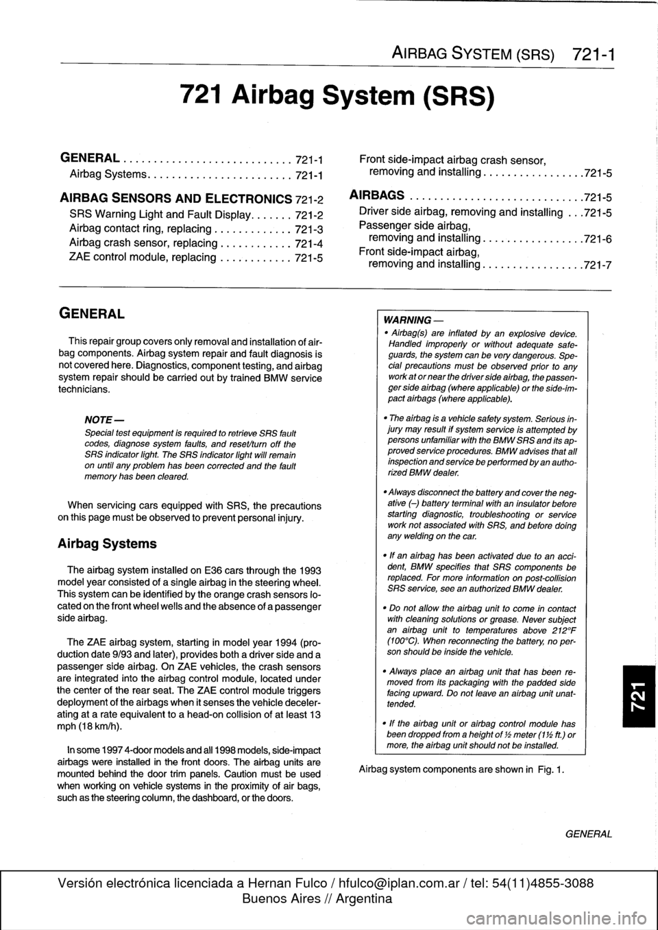
airbag
system
installed
on
E36
cars
through
the
1993
model
year
consisted
of
a
single
airbag
in
the
steering
wheel
.
This
systemcan
be
identified
by
the
orange
crash
sensors
lo-
cated
on
the
front
wheel
wells
and
the
absence
of
a
passenger
side
airbag
.
The
ZAE
airbag
system,
starting
in
model
year
1994
(pro-
duction
date9/93
and
later),
provides
both
a
driver
side
and
a
passenger
sideairbag
.
On
ZAE
vehicles,
the
crash
sensorsare
integrated
into
the
airbag
control
module,
located
under
thecenter
of
the
rear
seat
.
The
ZAE
control
module
triggers
deployment
of
the
airbags
When
it
sensos
the
vehicle
deceler-
ating
at
a
rate
equivalent
to
a
head-on
collisionof
at
least
13
mph
(18
km/h)
.
In
some
1997
4-door
models
and
all
1998
models,
side-impact
airbags
were
installed
in
the
front
doors
.
The
airbag
units
are
mounted
behindthe
door
trim
panels
.
Caution
mustbeused
when
working
on
vehicle
systems
in
the
proximity
of
air
bags,
such
as
the
steering
column,
the
dashboard,
or
the
doors
.
AIRBAG
SYSTEM
(SRS)
721-1
GENERAL
.
.
.
.
.
.
.
.
.
.
.......
.
......
.
.
.
.
721-1
Front
side-impact
airbag
crash
sensor,
removing
and
installing
....
.
.....
.
.....
.
721-5
AIRBAGS
..............
.
.
.
.
.
.
.
.
.
.
.
.
.
.
.
721-5
Driver
side
airbag,
removing
and
installing
.
.
.
721-5
Passenger
side
airbag,
removing
and
installing
..............
.
.
.721-6
Front
side-impact
airbag,
removing
and
installing
.
.
.
.
.
.
.
.
.
.
......
.721-7
WARNING
-
"
Airbag(s)
are
inflated
byan
explosive
device
.
Handled
improperly
or
without
adequate
safe-
guards,
the
System
can
be
very
dangerous
.
Spe-
cial
precautions
must
be
observed
prior
to
any
work
ator
near
the
driverside
airbag,
the
passen-
ger
side
airbag
(where
applicable)
or
the
side-im-
pact
airbags
(where
applicable)
.
"
The
airbag
is
a
vehicle
safety
system
.
Serious
in-
jury
may
result
if
System
service
is
attempted
by
persons
unfamiliar
with
the
BMW
SRS
and
its
ap-
proved
service
procedures
.
BMW
advises
that
all
inspection
and
service
be
performed
by
an
autho-
rized
BMW
dealer
.
"
Always
disconnect
the
battery
and
cover
the
neg-
ative
()
battery
terminal
with
an
insulator
before
startingdiagnostic,
troubleshooting
or
service
worknot
associated
with
SRS,
and
before
doing
any
welding
on
the
car
.
"
If
an
airbag
has
been
activated
due
to
an
acci-dent,
BMW
specifies
that
SRS
components
be
replaced
.
For
more
information
on
post-collision
SRS
service,
see
an
authorized
BMW
dealer
.
"
Do
not
allow
the
airbag
unit
to
come
in
contact
with
cleaning
solutions
orgrease
.
Never
subject
an
airbag
unit
to
temperatures
aboye
212°F
(100°C)
.
When
reconnecting
the
battery,
no
per-
son
should
be
inside
the
vehicle
.
"
Always
place
an
airbag
unitthat
has
been
re-
moved
from
its
packaging
with
the
padded
sidefacing
upward
.
Do
not
leave
an
airbag
unlt
unat-
tended
.
"
!f
the
airbag
unit
or
airbag
control
modulehas
been
dropped
froma
height
of
!
1
2
meter
(1
Y2
ft.)
ormore,
theairbag
unit
should
not
be
installed
.
Aírbag
system
components
are
shown
in
Fig
.
1.
GENERAL
Page 478 of 759
721-2
AIRBAG
SYSTEM
(SRS)
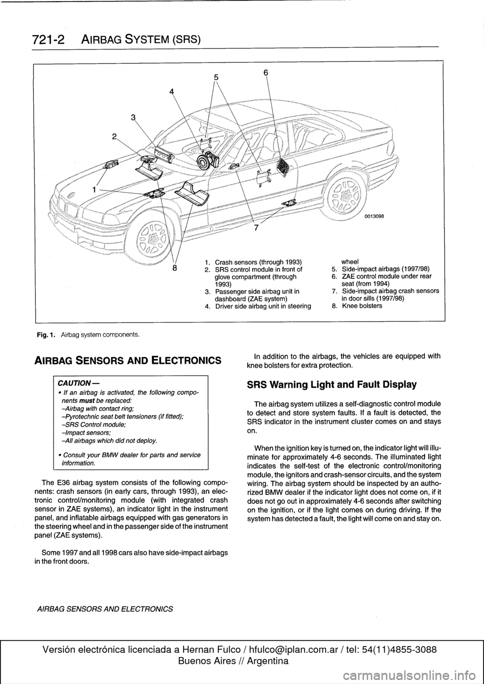
Fig
.
1
.
Airbag
system
components
.
AIRBAG
SENSORSAND
ELECTRONICS
CA
UTION-
"
If
an
airbag
is
activated,
the
following
compo-
nents
must
be
replaced
:
Airbag
with
contact
ring
;
-Pyrotechnic
seat
belt
tensioners
(if
fitted)
;
-SRS
Control
module
;
-Impact
sensors
;
All
airbags
which
did
not
deploy
.
"
Consult
your
BMW
dealer
for
parts
and
service
information
.
TheE36
airbag
system
consists
of
the
following
compo-
nents
:
crash
sensors
(in
earlycars,
through
1993),
an
elec-
tronic
control/monitoring
module
(with
integrated
crash
sensor
in
ZAE
systems),
an
indicator
light
in
the
instrument
panel,
and
inflatable
airbags
equipped
with
gas
generators
in
the
steering
wheel
and
in
the
passenger
side
of
the
instrument
panel
(ZAE
systems)
.
Some
1997
and
al¡
1998
carsalso
have
side-impact
airbags
in
the
front
doors
.
AIRBAG
SENSORS
AND
ELECTRONICS
1.
Crash
sensors
(through
1993)
wheel
2
.
SRS
control
module
in
front
of
5
.
Side-impact
airbags
(1997/98)
glove
compartment
(through
6
.
ZAE
control
module
under
rear
1993)
seat
(from
1994)
3
.
Passenger
side
airbag
unit
in
7
.
Side-impact
airbag
crash
sensors
dashboard
(ZAE
system)
in
door
silis
(1997/98)
4
.
Driver
side
airbag
unitin
steering
8
.
Knee
bolsters
In
addition
to
the
airbags,
the
vehicles
are
equipped
wíth
knee
bolsters
for
extra
protection
.
SRS
Warning
Light
and
Fault
Display
The
airbag
system
utilizes
a
self-diagnostic
control
module
to
detect
and
store
system
faults
.
If
a
fault
is
detected,
the
SRS
indicator
in
the
instrument
cluster
comes
on
and
stays
on
.
When
the
ignition
key
is
tumed
on,
the
indicator
light
will
illu-
minate
for
approximately
4-6
seconds
.
The
illuminated
light
indicates
the
self-testof
the
electronic
control/monitoring
module,
the
ignítors
and
crash-sensorcircuits,
and
the
system
wiring
.
The
airbag
system
should
be
inspected
byan
autho-
rized
BMW
dealer
if
the
indicator
light
does
not
come
on,
ifit
does
not
go
out
in
approximately
4-6
seconds
after
switching
onthe
ignition,
or
if
the
light
comes
on
during
driving
.
If
the
system
has
detected
a
fault,
the
light
will
come
on
and
stay
on
.