fuel filter BMW M3 1993 E36 Owner's Manual
[x] Cancel search | Manufacturer: BMW, Model Year: 1993, Model line: M3, Model: BMW M3 1993 E36Pages: 759
Page 185 of 759
160
Fuel
Tank
and
Fuel
Pump
GENERAL
.
.
.
.
.
.
...........
.
....
.
.
.
.
.
.
160-1
Operating
fuel
pump
for
tests
.
.
.
.
.
.
.......
.160-6
Fuel
Pump
Electrical
Tests
.
.
.
.
.
.
.
...
.
.
.
.
.
160-7
FUEL
TANK
AND
LINES
..
.
.
.
..........
160-2
Fuel
pump
electrical
circuit,
testing.
...
.
.
.
.
.
160-7
Fuel
tank,
draining
..
.
.
.
.
.
.
.
.
.
..........
160-2
Fuel
pump
power
consumption,
testing
.
.
.
.
.
.
160-7
Fuel
tank,
removing
and
installing
.........
160-3
Fuel
Delivery
Tests
....
.
.
.
...
.
.....
.
.
.
..
160-8
Fuel
Tank
Evaporative
Control
System
.....
160-4
Relieving
fuel
pressure
and
connecting
fuel
pressure
gauge
..
.
...........
.
.
.
..
160-8
FUEL
LEVEL
SENDERS
.
.
.
.
.
.......
.
.
.
160-4
System
pressure,
testing
.................
160-9
Fuel
level
senders,
testing
.
.
.
.
.
.......
.
.
.
160-5
Fuel
delivery
volume,
testing
.............
160-10
Fuel
leve¡
sender
and
fuel
pump
(right
side),
emoving
and
installing
.
.
.
.
.
.
160-5
TABLES
Fuel
leve¡
sender
(left
side),
a
.
FuelLeve¡
Sender
Resistances
...........
.
.
..
.160-5
removing
and
installing
.........
.
.
.
.
.
.
.
160-6
b
.
Fuel
Pump
Current
...
.................
..
...
160-8
c
.
Fuel
Pressure
Specifications
..............
.
..
160-10
FUEL
PUMP
.
.
.
................
.
.
.
.
.
.
.
160-6
d
.
Fuel
Pump
Delivery
Specifications
.........
.
..
160-10
Fuel
Pump
Fuse
and
Relay
.
.
.
....
.
.
.
.
.
.
.
160-6
GENERAL
This
repair
group
covers
service
information
specifically
for
The
cautions
and
warnings
on
this
page
should
beob
the
fuel
supply
system
.
Information
on
the
fue¡
injection
sys-
served
when
servicing
the
fuel
system
.
tem
is
covered
in
130
Fuel
Injection
.
NOTE-
Fue¡
filter
replacement
is
covered
in
020
Maintenance
Program
.
WARNING
-
"
The
fuel
system
is
designed
to
retain
pressure
even
when
the
ignition
isoff
.
When
working
with
the
fuel
system,
loosen
the
fuel
lines
slowly
toal-
low
residual
fuel
pressure
to
dissipate
gradually
.
Avoid
spraying
fuel
.
"
Before
beginning
any
work
on
the
fuel
system,
place
a
tire
extinguisher
in
the
vicinity
of
the
work
area
.
"
Fuel
is
highly
flammable
.
When
working
around
fuel,
do
not
disconnect
any
wires
that
could
cause
electrical
sparks
.
Do
not
smoke
or
work
near
heaters
or
other
tire
hazards
.
"
Always
unscrew
the
fuel
tank
cap
to
release
pres-
sure
in
the
tank
before
working
on
the
tank
or
fines
.
"
Do
not
use
a
work
light
near
any
fuel
.
Fuel
may
spray
onto
the
hot
bulb
causing
a
tire
.
"
Make
sure
the
work
area
is
properly
ventifated
.
FUEL
TANK
AND
FUEL
PUMP
160-1
CAUTION-
"
Prior
to
disconnecting
the
battery,
read
the
bat-tery
disconnection
cautions
given
at
the
front
of
this
manual
onpage
viü
.
"
Before
making
any
electrical
tests
with
the
ignition
tumed
on,
disable
the
ignition
system
as
de-
scribed
in
120
Ignition
System
.
Be
sure
the
bat-tery
is
disconnected
when
replacing
components
.
"
To
prevent
damage
to
the
ignition
system
or
the
electronic
fuel
system
components,
including
the
control
unit,
aiways
connect
and
disconnect
wires
and
test
equipment
with
the
ignition
off
.
"
Cleanliness
is
essential
when
working
with
the
fuel
system
.
Thoroughly
clean
the
fuel
fine
unionsbefore
disconnecting
any
of
the
fines
.
"
Use
only
clean
tools
.
Keep
removed
parts
clean
and
sealed
or
covered
with
a
clean,
lint-free
cloth,
especially
if
completion
of
the
repair
is
delayed
.
"
Do
not
move
the
car
while
the
fuel
system
is
open
.
"
Avoid
using
high
pressure
compressed
air
to
blow
out
fines
and
componente
.
High
pressure
can
rupture
infernal
seals
and
gaskets
.
"
Always
replace
seals
and
O-rings
.
GENERAL
Page 192 of 759
160-
8
FUEL
TANK
AND
FUEL
PUMP
UU131
tst5
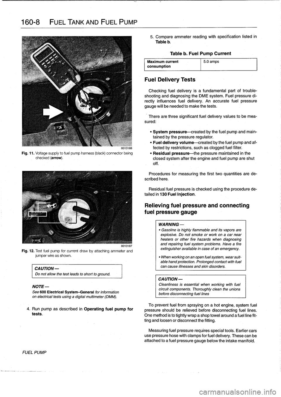
Fig
.
11
.
Voltage
supply
to
fuel
pump
harness
(black)
connector
being
checked
(arrow)
.
00131ts7
Fig
.
12
.
Test
fuel
pump
for
current
draw
by
attadhing
ammeter
andjumper
wire
as
shown
.
CAUTION-
Do
not
allow
the
test
leads
to
short
to
ground
.
NOTE-
See
600
Electrical
System-General
for
information
on
electricaltests
using
a
digital
multimeter
(DMM)
.
4
.
Run
pump
as
described
in
Operating
fuel
pump
for
tests
.
FUEL
PUMP
5
.
Compare
ammeter
reading
with
specification
listed
in
Table
b
.
Maximum
current
5
.0
amps
consumption
FuelDelivery
Tests
Table
b
.
Fuel
Pump
Current
Checking
fuel
delivery
is
a
fundamental
part
of
trouble-
shooting
and
diagnosing
the
DME
system
.
Fuelpressure
di-
rectly
influences
fuel
delivery
.
An
accurate
fuel
pressure
gauge
will
be
needed
to
make
the
tests
.
There
arethree
significant
fuel
delivery
values
to
bemea-
sured
:
"
System
pressure-created
by
the
fuel
pump
and
main-
tained
by
the
pressure
regulator
.
"
Fuel
delivery
volume-created
by
the
fuel
pump
and
af-
fected
by
restrictions,
suchas
clogged
fuel
filter
.
"
Residual
pressure-the
pressure
maintained
in
the
closed
system
after
the
engine
and
fuel
pump
areshut
off
.
Procedures
for
measuring
the
first
two
quantities
arede-
scribed
here
.
Residual
fuel
pressure
is
checked
using
the
procedurede-
tailed
in
130
Fuel
Injection
.
Relieving
fuel
pressure
and
connecting
fuel
pressure
gauge
WARNING
-
"
Gasoline
is
highly
flammable
and
its
vaporsare
explosive
.
Do
not
smoke
or
work
ona
car
near
heaters
or
other
fire
hazards
when
diagnosing
and
repairing
fuel
system
problems
.
Have
a
fire
extinguisher
available
in
case
of
an
emergency
.
"
When
working
onan
open
fuel
system,
wear
suit-
able
hand
protection
.
Prolonged
contact
with
fuel
can
cause
iflnesses
and
skin
disorders
.
CA
UTION-
Cleanliness
is
essential
when
working
withfuel
circuit
components
.
Thoroughly
clean
the
unionsbefore
disconnecting
fuel
fines
To
prevent
fuel
from
spraying
on
a
hotengine,
system
fuel
pressure
should
be
relieved
before
disconnecting
fuel
lines
.
One
method
is
to
tightly
wrap
a
shop
towel
around
a
fuel
line
fit-
ting
and
loosen
or
disconnect
the
fitting
.
Measuring
fuel
pressure
requires
special
tools
.
Earlier
cars
use
pressure
hose
with
clamps
for
fuel
delivery
.
These
can
be
attached
to
a
fuel
pressure
gauge
below
the
intake
manifold
.
Page 194 of 759
160-
1
0
FUEL
TANK
AND
FUEL
PUMP
3
.
Operate
fuel
pump
as
described
earlier
under
Operat-
ing
fuel
pump
for
tests
.
Check
that
fuel
pressure
cor-
responds
to
specifications
listed
in
Table
c
.
"
If
system
pressure
is
low,
repeat
test
whilegradually
pinching
off
return
hose
.
Pressure
should
rise
rapidly
.
If
not,fuel
pump
is
most
likely
faulty
.
"
If
system
pressure
is
too
high,
check
return
line
from
pressure
regulator
to
tank
.
Check
for
kinks
in
hose
.
Blow
compressed
air
through
line
to
check
for
block-
ages
.
If
no
faulty
canbe
found,
pressure
regulator
is
most
likely
faulty
.
See
130
Fuel
Injection
for
testing
and
replacementprocedures
.
Table
c
.
Fuel
Pressure
Specifications
Engine
1
Fuel
pressure
4-cylinder
M42/M44
3
.0
:e
0
.06
bar(43
.5
±0
.9
psi)
6-cylinder
M50/S50US
3
.0
:j-
0
.06bar(43
.5
t0
.9
psi)
M52/S52US
3
.5
t
0
.06
bar
(51
t0
.9psi)
CA
UTION-
Do
not
use
compressed
air
above
40
psi
to
blow
out
fines
or
components
.
Interna¡
damage
to
com-
ponents
may
result
.
4
.
When
finished,
disconnect
pressure
gauge
.
FUEL
PUMP
Fuel
delivery
volume,
testing
1
.
Disconnect
return
line
from
fuel
rail
in
engine
compart-
ment
.
2
.
Connect
a
length
of
hose
to
fitting
on
fuel
rail
and
place
open
end
of
hose
in
a
suitable
container
for
catching
fuel
(2-quart
capacity)
.
3
.
Run
fuel
pump
for
exactly
30
seconds
as
described
earlier
under
Operating
fuel
pump
for
tests
and
mea-
sure
fuel
collected
.
Refer
to
Table
d
.
WARNING-
Table
d
.
Fuel
Pump
Delivery
Specifications
Fuel
under
pressure
is
present
duringthe
test
.
Use
I
Engine
Delivery
rate
(30
seconds
@
12V)
hose
clamps
at
all
connections
.
4-cylinder
M42/M44
0
.875
fter
(0
.93
qt)
6-cylinder
M50/S50US
0
.875
fter(0
.93
qt)
M52/S52US
~
1
.12
liter
(1
.16
qt)
4
.
When
finished
testing,
reconnect
fuel
line
.
Tighten
all
hose
clamps
.
NOTE-
It
is
common
practice
to
replace
the
fuel
filter
any
time
the
fuel
pump
unit
is
replaced
.
Page 447 of 759
GENERAL
E36
cars
are
equipped
with
integrated
automatic
heating
and
air
conditioning
systems
.
Many
of
the
procedures
given
in
this
repair
group
require
that
the
A/C
refrigerant
charge
be
evacuated
using
specialized
equipment
.
See
A/C
System
Warningsand
Cautions
later
in
this
repair
group
.
HEATER
AND
CONTROLS
Blower
motor,
removing
and
installing
NOTE-
On
6-cylinder
cars,
the
plastic
top
enginecover
and
fuel
rail
covermustbe
removed
.
The
fuel
injectorhamess
re-
taining
screws
must
be
removed
and
the
harness
set
aside
.
The
engine
control
module
(ECM)
cover
must
be
removed,
the
control
unit
connectors
unplugged
and
the
harness
pulled
out
of
the
way
.
See
130
Fuel
Injection
.
1
.
Disconnect
negative
(-)
cable
from
battery
.
2
.
Open
hood
.
Unclip
engine
bulkhead
plenum
grille
at
base
of
windshíeld
and
remove
grille
.
See
Fig
.
1
.
HEATING
AND
AIR
CONDITIONING
640-1
640
Heating
and
Air
Conditioning
GENERAL
.
...
.
....
.
.
.
.
.
.
.
.
.
.......
.
.
.
640-1
Heater
andA/C
air
distribution
motor,
replacing(rotary-knob)
.
.
...
.
.
.
.......
.
640-10
HEATER
AND
CONTROLS
.
.....
.
.
.
.
.
.
.640-1
Rear
Window
Defogger
.
.
.
.
.
.
.
.
.
.
...
.
.
.
640-10
Blower
motor,
removing
and
installing
.
.
.
.
.
.
640-1
Rear
Window
Blower
(convertible
models)
.
.640-10
Blowermotor
resistor
pack,
replacing
.
.
.
.
.
.
640-3
AIR
CONDITIONING
.
.
.
.
.
.
.
.
.
.
.
.
.
.
.
.
.
.
640-11
Heater
valve,
replacing
...........
.
.
.
.
.
.
.
640-3
Heater
box,
removing
and
installing
.
.
.
.
.
.
.
.
640-4
A/CSystem
Warnings
and
Cautions
.
.
.
.
.
.
:640-11
Heater
core,
replacing
.....
.
.
:
....
.
.
.
.
.
.
.
640-6
A/C
compressor,
replacing
.
.
::.
:
:
.
.
.
.
.
.
.
.640-12
Heater
core
temperature
sensor,
replacing
.
.
640-7
A/C
Compressor
Clutch
.
.
.
.
.
.
.
:
.
.
.
.
.
.
.
.
.
640-13
Heater
andA/C
Control
Head
.
.
....
.
.....
.
640-7
A/C
condenser,
replacing
.
.
.
.
.
.
.
.
.
.
.
.
.
.
.
.
640-14
Heater
andA/C
control
head,
removing
A/C
receiver/drier,
replacing
.
.
.
.
.
.
.
.
.
.
.
.
.
640-15
and
installing
(rotary-knob)
.
.
....
.
......
640-7
A/C
expansion
valve,
Heater
andA/C
control
head,
removing
removing
and
installing
...
.
.....
.
.
.
.
.
.
.
640-16
and
installing
(digital-display)
.
.....
.
.....
640-8
A/C
evaporator,
removing
and
installing
.
.
..
640-17
Heater
andA/C
control
module,removing
A/C
evaporator
temperature
sensor,
and
installing
(rotary-knob)
.
.
...
.
.
.
.
.
.
.
.
640-8
replacing
.
.
.
.
.
.
..............
.
.
.
.
.
..
640-17
Heater
andA/C
control
module,removing
A/C
microfilter,
replacing
......
.
....
.
.
.
..
640-18
and
installing
(digital-display)
.
...
.
.
.
.
.
...
640-8
Sensor
fan
for
interior
temperature,
TABLES
replacing
.
.
.
....
.
.
.
.
.
.
.
.
.
.
.
.
.
.
.
.
.
.
.
.
640-9
a
.
Blower
Motor
Test
Values
.........
...
.
.
......
640-3
Heater
andA/C
AirDistribution
Motors
.
.
.
.
.
.
640-9
b
.
Heater
Core
Temperature
Sensor
Test
Values
...
.640-7
c
.
Evaporative
Temperature
Sensor
Test
Values
...
640-17
d
.
A/C
System
Fluid
Capacities
(total)
..
..........
640-18
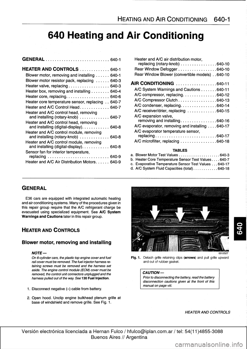
0012527
Fig
.
1
.
Detach
grille
retaining
clips
(arrows)
and
pull
grille
upward
and
out
of
rubbergasket
.
CAUTION-
Prior
to
disconnectiog
the
battery,
read
the
battery
disconnection
cautionsgiven
at
the
front
of
this
manual
onpage
viii
.
HEATER
AND
CONTROLS
Page 523 of 759
LEFT
-
LEFT
I
I
-
RIGHT
-
RIGHT
I
(
)
TAIL
(
)
TAIL
I
I
(
)
TAIL
(
)
TAIL
I
-
LIGHT
-
LIGHT
I
I
LIGHT
-
LIGHT
I
I
II
I
II
I
I
_
I
(
)
BACK-
LEFTUP
(
^
)
BRAKE
I
I
(
^
)
BACK
FIGHT
UP
(
_
)
BRAKE
LIGHT
LIGHT
LIGHT
LIGHT
I
I
II
I
I
______________J
______________J
64882
-
7993
ONLY
ELECTRICAL
WIRING
DIAGRAMSELE-39
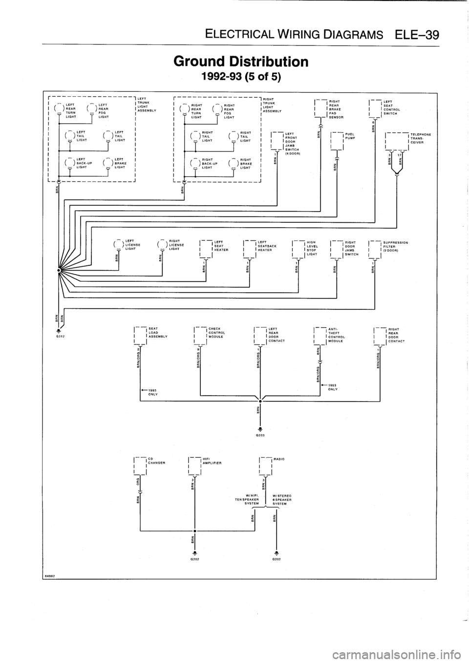
Ground
Distribution
1992-93
(5
of
5)
,LEFT
rFIGHT
I
_
_
LEFT
"~LEFT
(TRUNK
I
TRUNK
I
RIGHT
LEFT
I
G
LIGHT
REAR
REAR
RIGHT
~'
RIGHT
I
I
REAR
I
(SEAT(ASSEMBLY
I
(
)
REAR
(
)
BEAR_
(ASSEMBLY
I
(BRAKE
I
(CONTROL
I
-
TURN
FOG
I
I
TURN
FOG
I
I
(
PAD
I
(
SWITCH
LIGHT
LIGHT
i
i
LIGHT
LIGHT
i
SENSOR
B
()
LEFT
LICENSE
(
)
LICENSE
I
(
SEAT
I
I
SEATBACK
I
(
LEVEL
I
(
DOOR
I
I
FILTER
ESSION
LIGHT
LIGHT
I
(
HEATER
I
l
HEATER
I
V
(
STOP
I
v
(
JAMB
I
v
I
(2DOOR)
I
I
I
__I
I
_
(
LIGHT
I
-(SWITCH
I__I
Y
Y
SEAT
I
CHECK
LEFT
ANTI-
RIGHT
(
I
LOAD
CONTROL
REAR
I
(
THEFT
I
I
REAR
G312
I
I(
ASSEMBLY
I
(
MODULE
I
(
DOOR
I
(
CONTROL
I
(
DOOR
I
-
I
I
_
I
I
_I
CONTACT
I
_I
MODULE
I
_I
CONTACT
CD
HIFI
RADIO
I
(
CHANGER
I
(
AMPLIFIER
i
II
I
I
I
I
I
WIHIFI
.
I
WISTEREO
TENSPEAKER
BSPEAKER
SYSTEMSYSTEM
I
LEFT
FUEL
TELEPHONE
(
FRONT
I
(
PUMP
I---
I
TRANS-
DOOR
I
I
I
I
CEIVER
I
(JAMB
I
I
I
SWITCH
,Y
(4DOOR
I
=
Y
~~Y
Page 527 of 759
ELECTRICAL
WIRING
DIAGRAMSELE-43
r----------_-__--,LEFT
r---__-------~_--,FIGHT
I
-
RIGHT
LIT
LEFT
"-
LEFT
I
IGHT
K
I
_
RIGHT
'
RIGHT
I
'TRUNK
SEMBLY
I
(
REAR
I
(
SEAT
I
(
)
REAR
(
)
REAR
I
gSSEMBLV
I
(
)
REAR
(
)REAR
I
I
(
BRAKE
I
(
CONTROL
AS
I
-
TURN
-
FOG
I
I
-
TURN
-
FOG
I
I
(
PAD
I
-(
SWITCH
I
LIGHT
LIGHT
I
I
LIGHT
LIGHT
I
SENSOR
I
I
I
I
B
LEFT
SEAT
I
(LUMBAR
I
-
LEFT
-
LEFT
_RIGHT
RIGHT
I
I
(
)
TAIL
(
)
SUPPO
TAIL
I
I
(
)
TAIL
(
)
TAIL
I
I
(
LEFT
I
,
FUEL
I
I
MO70RRVALVE
LIGHT
-
LIGHT
i
i
LIGHT
-~
LIGHT
i
I
I
DRM9T
I
(
PUMP
(I9SB)
I
I
I
I
I
v
I
SWITCH
I
T
T
(4
DOOR)
84322
1
G312
_
LEFT
'
LEFT
>
BACK-UP
(
)
BRAKE
LIGHT
LIGHT
G203
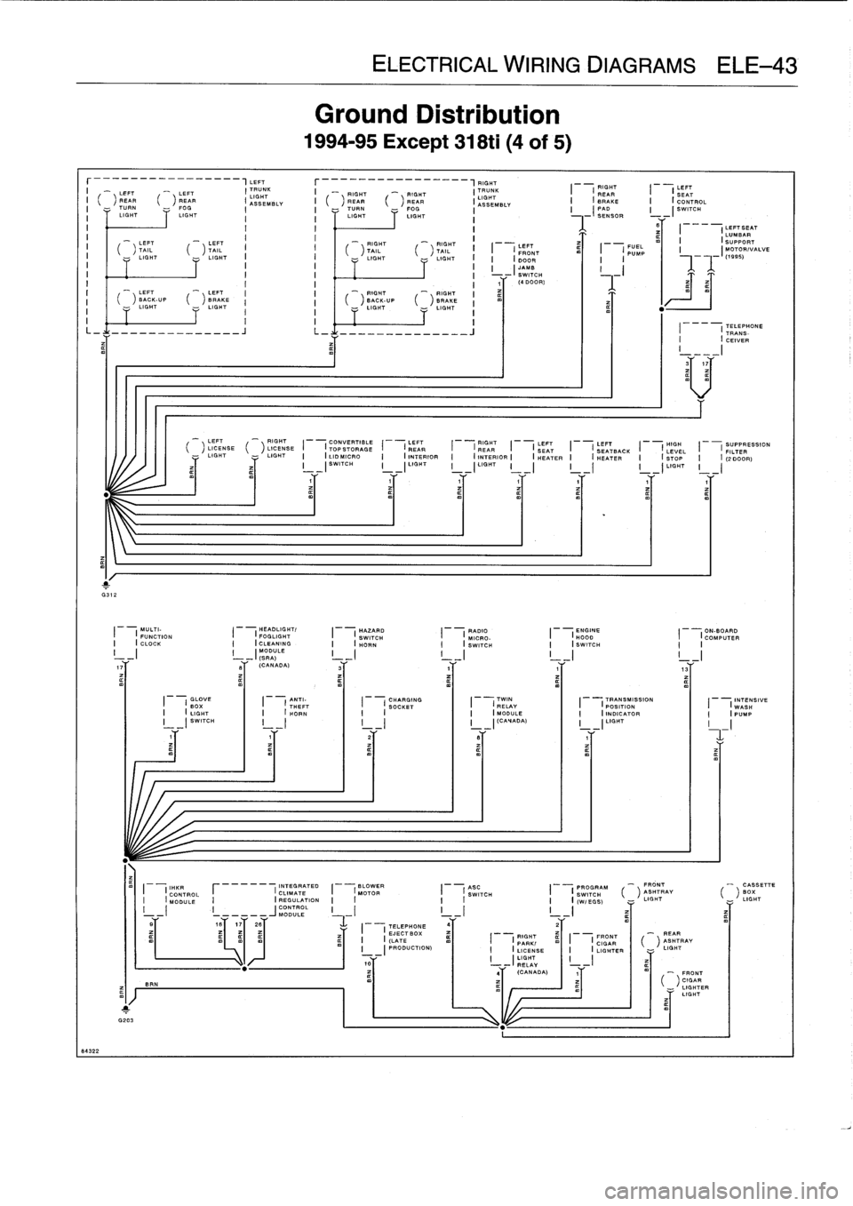
Ground
Distribution
1994-95
Except
318ti
(4
of
5)
'
RIGHT
"'
RIGHT
(
)
BACK-UP
(
>
BRAKE
LIGHT
,,
LIGHT
L_1--------------
J
L-1
--------------
i
I
_I
_I
_I
MODU
(SRA)
LE
I
_I
I
_I
I
_I
I
_I
17T
SY
(CANADA,
3T
Y
IaY
,
1
TELEPHONE
I
---
I
TRANS-CEIVER
I
._I
3T
,
7Y
_LEFT
-
RIGHT
_
CONVERTIBLE
LEFT
_RIGHT
_
LEFT
_
LEFT
_
HIGH
SUPPRESSION
(
)
LICENSE
(
)
LICENSE
I
I
TOPSTORAGE
I
(
REAR
I
(
REAR
I
(
SEAT
I
I
SEATBAIK
I
(
LEVEL
I
(
FILTER
LIGHT
LIGHT
I
I
LID
MICRO
I
(
INTERIOR
I
ANTERIOR
(
Y
(
HEATER
I
Y
(
HEATER
I
v
.
(
STOP
I
v
I
(2
DOOR)
I
I
SWITCH
I
I
LIGHT
I
_
I
LIGHT
_-
I
I
-
I
I
_
I
LIGHT
I-I
Y
YY
MULTI-
HEADLIGHT/
HAZARD
RADIO
ENGINE
ON-BOARD
I
(
FUNCTION
I
I
FOGLIGHT
I
(
SWITCH
I
(
MICRO-
I
I
H000
I
(
COMPUTER
I
I
CLOCK
I
I
CLEANING
I
(
HORN
I
(
SWITCH
I
(
SWITCH
I
I
GLOVE
ANTI-
CHARGING
TWIN
TRANSMISSION
INTENSIVE
I
(
BOX
I
(
THEFT
I
(
SOCKET
I
(
RELAY
I
(
POSITION
I
(
WASH
I
(
LIGHT
I
(
HORN
I
I
I
(
MODULE
I
(
INDICATOR
I
(
PUMP
I
_
(
SWITCH
I
_
I
I
-I
L-1
(CANADA)
I
-(LIGHT_
_
I
I
IT
IT
21'
ST
,Y
IHKR
INTEGRATED
BLOWER
ABC
OGRAM
-
FRONT
-
CASSETTE
CONTROL
I
r
-
CLIMATE
I
(MOTOR
II
I
:PR
ASHTRAY
BOX
SWITCH
SW
I
TCH
(
MODULE
I
(
REGULATION
I
i
I
I
I
(W/EGS)
LIGHT
LIGHT
I
i
-----JMODULE
L
I
I
I
I
I
`7'
I
1617
26
I
(TELEPHONE
4
"I
4
_
4
EJECTBOX
RIGHT
FRONT
REAR
I
(
(LATE
I
(
PARK(
I
(
CIGAR
(
)
ASHTRAY
-(
PRODUCTION)
I
(
LICENSE
I
(
LIGHTER
-
LIGHT
I
I
LIGHT
-
I
RELAY
4
(CANADA)
1
FRONT
BRN
(
^
)
CIGAR
LIGHTER
LIGHT
Page 533 of 759
TELEPHONE
CONVERTIBLE
RIGHT
REAR
CENTRAL
RIGHT
DRIVERS
___
I
I
_
__
_
_
___
_7RAN5-
I
I
TOpSTORAGE
I
I
BRAKEPAD
I
(
LOCKING
(
)LICENSE
I
II
I
CEIVER
I
LID
MICRO
I
I
SENSOR
I
(
SWITCH
LIGHT
SEAT
[-
,
RIGHT
-(
(1996)
I
(
__
I
I
I
_I__
I
(
SWATCH
SWITCH
31'
17Y
LUGGAGE
COMPARTMENT
TELEPHONECONNECTOR
(1997)
DRIVERS
1
-
1
FUEL
I
IJAMB
I
I
IPUMP
I
_I
SWITCH
I
I
_I
F__
f
____
_
_-_---
------
1997WITH
m
I
ALL
CONVERTIBLE
OTHERS
CONVERTIBLE
LEFT
I
I
REAR
I
I
TOP
I
I
REAR
WINDOW
I
(CONTROL
i
(INTERIOR
I
(BLOWER
-
I
MODULE_
I
-
I
LIGHT
I
-I
SWITCH
Y
V
1
SUPPRESSION
RIGHT
LEFT
-
LEFT
I
I
RAR
I
I
(
FILTER
I
(
REAR
~
i
h
)
TAIL
(
)
TAIL
I
(
REAR
I
(
WINDOW
I
I
(2
DOOR)
I
(
I
LIGHT
LIGHT
(
INTERIOR
m
I
(
BLOWER
LIGHT
I
I
LIGHT
INTERIOR
-
-I
1
2
_
(
HARD
1
2
I
DRIVERS
LEFT
I
-
LEFT
^'
LEFT
I(
SEAT
m
I
(
REAR
BACK-UP
BRAKE(CONNECTOR(
I
I
DRIGHT
Z
EFOGGEfl
I
(REAR
I
(
HEATER
I
(
INTERIOR
I
-
LIGHT
-
LIGHT
II
_I
I
I
I
(DOOR
I
_
I
I
-
(
LIGHT
I
I
I
m
I
y,
-I
(1
BR~1
cT
1
2
L_
I
IT-PD
ml
-
iCONNECTOR1
I
I
1
G312
0312
(CONVERTIBLE)
MULTI-
HEADLIGHT/
HAZARD
RADIO
ENGINE
TRANSMISSION
I
(
FUNCTION
I
I
FOGLIGHT
I
I
I
I
FINAL
B
LOWER
I
I
CLOCK
I
(
CLEANING
SWITCH
SWITCH
I
(
SHOWIODTC
I
(
INDICATOR
I
I
I
I
I
I
I
(
I
(
H
I
(
I
(
STAGE
MOTOR
UNIT
III
I
I
I
MO
1996)
LE
_
_
_
_
__
_
I_
_
I
I
I
_
_(1996)
I
I
I
(
LIGHT
I
-I
I
I
17
g~
(CANADA)
gY
17
1T
tY
Gy
I
I
~j
AUTOMATIC
I
(CLIMATE
CENTER
I
(CONTROL
GLOVE
SERVOTRONIC
CHARGING
ON-BOARD
INTENSIVE
-
I
MODULE
I
(
BOX
I
(
CONTROL
I
(
SOCKET
CONSOLE
m
I
(COMPUTER
m
I
IWgSH
I
_
I
(LIGHT
mI
I
(
MODULE
mI
I
I
MI
TELEPHONE
II
(()
II
I
1996
PUMP
1997
W/IHKA
InOR
ALL1996
_-__41,
_
-F_---_-0-9-_----f--f----0--0_----_f-f--_----___-----
I
-
(
(1997)
I
-(
(1997)
I
_
I
AS
C
FRONT
I
I
SWITCH
I
I
CIGAR
I
I
I
I
LIGHTER
I
_I
_I
I
_I
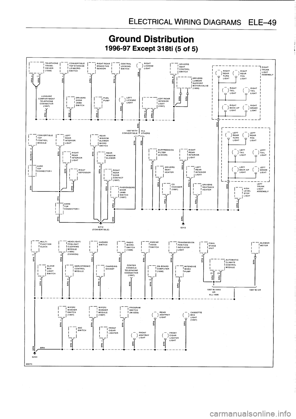
Ground
Distribution
1996-97
Except
318ti
(5
of
5)
-
LEFT
LICENSE
-
LIGHT
ELECTRICAL
WIRING
DIAGRAMS
ELE-49
I
DRIVERS
LEFT
PASSENGERS
I
OHANGER
I
ISEATBACK
HIGH
TRUNK
I
(
DOOR
I
(
(1997)
I
(
HEATER
I
I
LIGHT
I
i
I
I
I
II
I
LEVEL
JAMB
ASSEMBLY
I
SWITCH
I
I
LIGHT
WIPER/
WIPER/
PROGRAM
I
(
WASHER
I
(
WASHER
I
(
SWITCH
I
(
SWITCH
I
(
MODULE
I
I
(W/EGS)
-
FIGHT
"'
RIGHT
ITRUNK
REARTURN
-
~FOGR
iASSEMBLY
~I
I
I
DRIVERS
I
LIGHT
LIGHT
LUMBAR
II
(SUPPORT
I
II
MOTOR/VALVE
I
_
I
\
(1996)
i
-~
RIGHT
~--'
T
A
IL
I
\
FRONT
-,
FRONT
LGGAF
HTAY
I
-'LIGHTER
LIGHT
-
REAR
-
CASSETTE
_
LIGHT
RAY
6
GHT
Y
Y
(1997)
mI
SRN
1
G203
69073
-
RIGHT
RIGHT
BACK-UP
(
)
BRAKE
LIGHT
-
LIGHT
L_-~
-
___________J
r
-
Y
I
(
)
REAR
(
)
REAR
I
-
TURN
FOG
I
LIGHTLIGHT
I
Page 537 of 759
RIGHT
FUEL
RIGHTREAR
CENTRAL
LEFTREAR
DRIVER'S
---
(
FEAR
I
(
PUMP
I
I
BRAKE
PAD
I
(
LOCKING
I---
(
INTERIOR
I---
(
SEAT
INTERIOR
(
I
I
(
SENSOR
I
(
SWITCH
I
(
LIGHT
I
(
LUMBAR
(
LIGHT
I
I
I
I
I_
_
_
I
_
_
I
I
(
SUPPORT
v
o
I
~
~
eT
,T
,T
3/~
MOTORIVALVE
LUGGAGE
COMPARTMENT
TELEPHONE
CONNECTOR
I
I
DRIVER'S
DOOR
I
(JAMB
I
_I
SWITCH
I
-
LEFT
-
LEFT
CONVERTIBLE
LEFT
FEAR
CONVE
WIT
R
H
TIBLE
OT
A
HLEL
RS
_
_
CD
I
(
)
FEAR
(
)
REAR
I
(
TOP
I
FEAR
I
(
WINDOW
I
(CHANGER
I
T
TURN
--
FOG
I
CONTROL
I
(
INTERIOR
I
(
BLOWER
I
I
LIGHT
LIGHT
I
(
MODULE
I(
LIGHT
I
I
WORD
m
m
_
_
SW
-
H
I
I
-
LEFT
_
LEFT
I1
REAR
CONVERTIBLE
RIGHT_
_
_
_
_
_
I
(
)
TAIL
(
)
TAIL
II
I
(
DEFOGGER
I
I
TOP
STORAGE
I
(REAR
I
-
LIGHT
-
LIGHT
I
I
I
v
(LID
MICRO
I
v
(INTERIOR
I
I
SWITCH
I
_(
LIGHT
I
I
-
-
-
I
I1
1
2
I
-
LEFT
UP
-
LEFT
HARD
RIGHT
PASSENGER'S
FILTER
SID
.
DRIVER'
ACK-
BRAKE
S
I
(
(
I
I
(
TOP
I
(
REAR
I
(
DOOR
I
(
m
I
I
EATBACK
I
LIGHT
LIGHT
II
ICONNECTORI
I
I
(INTERIOR(
ml
I
IJgMB
I
I(2DOOR)
HI
(EATER
I
I
I_
I
I
I
(
LIGHT
I
I
I
_(
SWITCH
I
_I
I
I
-I
I
L_1
---J
10441
5
(HARD
TOP
ICONNECTOR1
_1
MULTI-
HAZARD
ENGINE
TRANSMISSION
FINAL
AUTOMATIC
BLOWER
(
FUNCTION
I
(
SWITCH
I
(
HOOD
I
(
POSITION
(
STAGE
I
(
CLIMATE
I
(
MOTOR
(
CLOCK
I
I
I
(
SWITCH
I
(
INDICATOR
I
(
UNIT
I
(
CONTROL
I
I
mI
/
1
G203
BRN
GLOVE
I
CHARGING
BIGHT
I
'
SOCKET
I-_I
I
_I
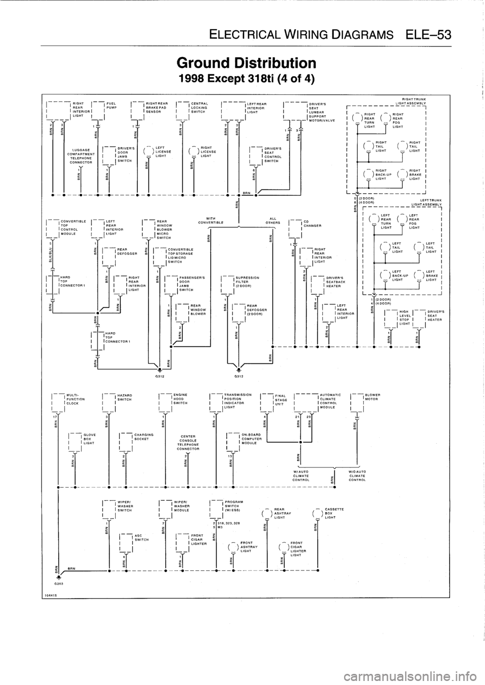
Ground
Distribution
1998Except
318ti
(4
of
4)
LEFT
-
RIGHT
LICENSE
(
)
LICENSE
LIGHT
-
LIGHT
1
FEAR
PEAR
I
I
WINDOW
I
I
DEFOGGER
I
I
BLOWER
I
I
(2
DOOR)
~%___'j
__\I/
G312
G312
CENTER
CONSOLE
TELEPHONE
CONNECTOR
I
I
WIPER/
I
(
WIPER/
I
(
PROGRAMWASHER
WASHER
SWITCH
I
(SWITCH
I
(
MODULE
I
I(WIEGS)
-
REAR
-
CASSETTE
II
II
II
('T
RAV
(B
_
__
LIGH_'IGHT
71
521
318,
323,
328
v3
ELECTRICAL
WIRING
DIAGRAMS
ELE-53
I
I
DRIVER'S
SEAT
I
(CONTROL
_I
SWITCH
ASO
FRONT
I
I
SWITCH
I
I
CIGAR
I
I
I
(
LIGHTER
-
FRONT
FRONT
ASHTRAY
CGAR
L
GHT
LIGHTER
LIGHT
I-
LEFT
FEAR
I
INTERIOR
I
-
I
LIGHT
RIGHTTRUNK
-_------_IGH-T_SSE=BL=
I
-
RIGHT
"~
RIGHT
I
(
)
REAR
(
)REAR
I
TURN
FOG
I
LIGHTLIGHT
RIGHT
~'
gIGHT
I
TAIL
(
)
TAIL
LIGHT
-
LIGHT
I
I
_
RIGHT
-
RIGHT
(
)
BACK-UP
(
)BRAKE
I
I
LIGHT
I
I
I
L_
___J
"T2
DEEP)
LEFTTRUNK
LIGHT
_
__
_
_
_
_
__
¢~
LIGHTASSEMBLV
a
r__
(2
DOOR)
(4
DOOR)
I
I
1
I
HIGH
DRIVER'S
I
LEVEL
1
SEAT
I
I
STOP
I
HEATER
I
-)
LIGHT
I
-
I
Page 540 of 759
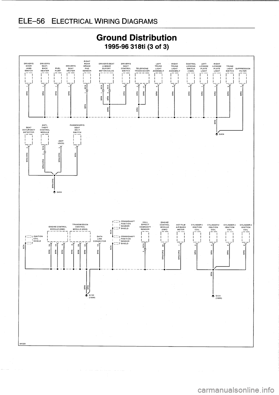
ELE-56
ELECTRICAL
WIRING
DIAGRAMS
ANTI-
PASSENGER'S
SEAT
THEFT
SEAT
OCCUPANCY
CONTROL
BELT
DETECTOR
MODULE
SWITCH
84320
RIGHT
DRIVER'S
DRIVER'S
REAR
DRIVER'S
SEAT
DRIVER'S
LEFT
RIGHT
CENTRAL
LEFT
RIGHT
DOOR
SEAT-
DRIVER'S
BRAKE
LUMBAR
SEAT
TRUNKTRUNK
LOCKINGLICENSE
LICENSE
TRUNK
JAMB
BACK
FUEL
SEAT
PAD
SUPORT
CONTROL
TELEPHONE
LIGHT
LIGHT
SWITCH
PLATEPLATE
LIGHT
SUPPRESSION
SWITCH
HEATER
PUMP
HEATER
SENSOR
MOTOR/VALVE
SWITCH
TRANSCEIVER
ASSEMBLY
ASSEMBLY
(1995)
LIGHT
LIGHT
SWITCH
FILTER
F
-
1
--,
1
-
7
I
_-
I
F
-
F
-,
1
-
7F
-
F
-
F
-
I
--,
1
--,
1
-
7
I
I
I
~
I
I
I
I
,
I
,
I
~
I
I
I
I
I
I
I
,
I
,
I
I
I
I
I
I
I
L
-I
L
-I
I
I
L
-I
L
-I
L
-I
L
-I
!
_I
L
-I
L
-I
(NOT
USED)
1
G404
1
G103
(1998)
Ground
Distribution
1995-96
318ti
(3
of
3)
Z
G404
CRANKSHAFT
HALL
ENGINE
TRANSMISSION
POSITION
EFFECT
CONTROL
HOTFILM
CYLINDER
1
CYLINDER2
CYLINDER
3
CYLINDER4
ENGINECONTROL
CONTROL
SENSOR
CAMSHAFT
MODULE
AIR
MASS
IGNITION
IGNITION
IGNITION
IGNITION
MODULE(DME)
MODULE(EGS)
-
j
SHIELD
SENSOR
,~
(DME)
METER
COILCOIL
COILCOIL
----
r
I
I
-
I
I
i
I
i
IGNITION
I
I
I
DATA
CRANKSHAFT
I
COIL
LINK
POSITION
I
IIII
I,
SHIELDL
CONNECTOR
SHIELD
SENSOR
I
I
I
III
I
III
I
II
I
__
_Y
_TY
SE
mY
Y
~Y
=Y
<___
_
~-
1"
=(
Y
T
Y
Y
1
G131
(1996)
Page 543 of 759
RIGHT
DRIVER'S
DRIVER'S
REAR
HIGH
REAR
LEFT
RIGHT
LEFT
RIGHT
DOOR
SEAT-
DRIVER'S
BRAKE
LEVEL
CENTERTRUNK
TRUNK
CENTRAL
LICENSELICENSE
TRUNK
JAMB
BACK
FUEL
SEAT
PAD
CD
STOP
TELEPHONE
INTERIOR
LIGHT
LIGHT
LOCKING
PLATEPLATE
LIGHT
SUPPRESSION
REAR
SWITCHHEATER
PUMP
HEATER
SENSOR
CHANGER
LIGHT
CONNECTOR
LIGHT
ASSEMBLYASSEMBLY
SWITCH
LIGHTLIGHT
SWITCH
FILTER
DEFOGGER
I
--,
I
i
F-
I
I
_-
I
1
-
7
1
-
7
F
-
,
I
--
,
F
-,
1
--,
I
1
--,
1
-
7
I
-
i
I
-
i
I
i
I
i
I
I
I
I
I
I
I
I
I
I
I
I
I
I
I
I
I
I
I
I
I
I
I
I
I
I
I
I
I
I
I
I
I
II
!
_I
!
_I
!
_I
I
_I
!
_I
!
_I
L-1
L-1
L
-I
L
-I
L-1
L-1
L-1
L-1
!
_I
L-1
Y
Y
-T
r
-r
-T
Y
Y
Y
rY
-T-T
r
Y
=r
ANTI-
PASSENGER'SPASSENGER'S
DRIVER'S
DRIVER'S
ASS
LEFT
RIGHT
SEAT
THEFT
SIDE
SEAT
SEAT
SIDE
A
BS
SLIP
PUMP
FRONT
FRONT
ASSOCCUPANCY
CONTROL
IMPACT
I
BELT
BELT
IMPACT
HYDRAULIC
CONTROL
MOTOR
SPEED
SPEED
CONTROL
DETECTOR
MODULESENSOR
SWITCH
SWITCH
SENSOR
UNIT
MODULE
RELAY
SENSOR
SENSORMODULE
F
-,
I
I
I
I
F
-
I
F-
I
F
-
II
I
I
I
I
I
1
I
I
I
I
II
_I
Y
=1
-T-T
Y
=f
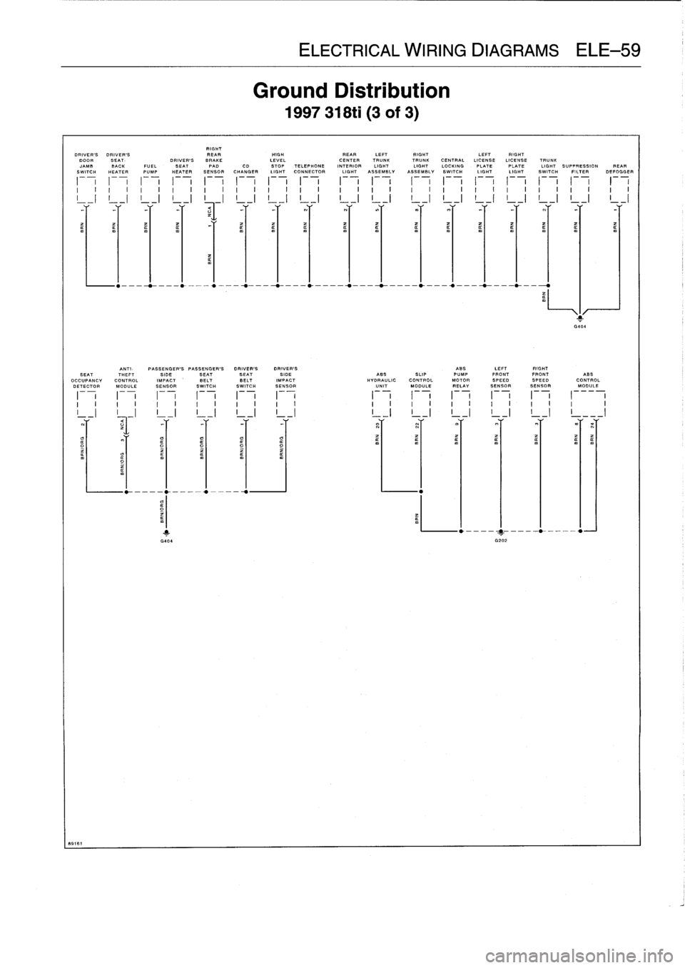
ELECTRICAL
WIRING
DIAGRAMS
ELE-59
Ground
Distribution
1997
318ti
(3of
3)
IIII
F
-,
F
-,
F
-,
I
II
I
I
I
I
I
I
I
I
I
I
I