outside mirror BMW M3 1993 E36 Workshop Manual
[x] Cancel search | Manufacturer: BMW, Model Year: 1993, Model line: M3, Model: BMW M3 1993 E36Pages: 759
Page 306 of 759
400-
4
BODY-GENERAL
INTERIOR
EQUIPMENT
E36
interiors
have
a
unique
character,
with
a
combínation
of
sporty
features
and
innovative
design
.
Al¡
body
versions
were
made
in
a
wide
choice
of
interior
and
exterior
colors
.
New
colors
with
matching
leather
and/or
fabric
upholstery
were
in-
troduced
for
each
model
year,
including
light-alloy
wheels
in
new
designs
.
Driving
comfort
is
enhanced
by
power
steering,
tilt
steering
wheel
(optional),
height-adjustable
front
seats,
and
electrical-
ly
adjustable
and
heated
rear-view
mirrors
.
Inside
thecar
there
are
reading
lights
at
four
seating
positions
.
Seats
and
Seat
Belts
NOTE-
Theseat
base
usedon
cars
with
pyrotechnic
seatbelt
Anatom¡cal
ly-correct
seats
are
constructed
from
polyure-
tensioners
is
not
interchangeable
with
the
earlier
seat
thane
foam
containing
areas
or
"zones"
of
different
firmness
.
base
.
The
seat
bases
have
steel
springs
for
added
support
and
strength
.
The
power
seats
are
provided
with
conveniently
lo-
Instruments
and
Controls
cated
switches
along
the
outside
edge
of
the
seat
.
Heated
seats
are
an
option
in
all
models
.
See
520
Seats
for
more
de-
Everything
in
the
interior
passenger
compartment
essential
tails
.
to
the
driver
is
logically
grouped
and
easy
to
reach
.
Al¡
instru-
ments
and
controls
havebeen
arranged
ergonomically
and
The
M3
sport
seat
is
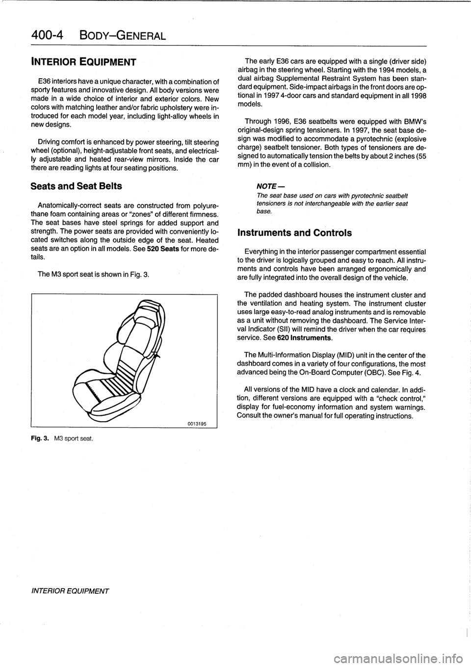
shown
in
Fig
.
3
.
are
fully
integrated
into
the
overall
design
of
the
vehicle
.
Fig
.
3
.
M3
sport
seat
.
INTERIOR
EQUIPMENT
0013195
The
early
E36
cars
areequipped
with
a
single
(driver
side)
airbag
in
the
steering
wheel
.
Startingwith
the
1994
models,
a
dual
airbag
Supplemental
Restraint
System
has
been
stan-
dard
equipment
.
Side-impact
airbags
in
the
front
doors
are
op-
tional
in
1997
4-door
cars
and
standard
equipment
in
all
1998
models
.
Through
1996,
E36
seatbelts
were
equipped
with
BMW's
original-designspring
tensioners
.
In
1997,
the
seat
base
de-
sign
was
modified
to
accommodate
a
pyrotechnic
(explosive
charge)
seatbelt
tensioner
.
Both
types
of
tensioners
arede-
signed
to
automatically
tension
the
belts
by
about2
inches(55
mm)
in
the
event
of
a
collision
.
The
padded
dashboard
houses
the
instrument
cluster
and
the
ventilation
and
heating
system
.
The
instrument
cluster
uses
large
easy-to-read
analog
instruments
and
is
removable
as
a
unit
without
removing
the
dashboard
.
The
Service
Inter-
val
Indicator
(SII)
will
remind
the
driver
when
thecar
requires
service
.
See
620
Instruments
.
The
Multi-Information
Display
(MID)
unit
in
thecenter
of
the
dashboard
comes
in
a
variety
of
four
configurations,
the
most
advanced
being
the
On-Board
Computer
(OBC)
.
See
Fig
.
4
.
Al¡
versions
of
the
MID
have
a
clock
and
calendar
.
In
addi-
tion,
different
versions
areequipped
with
a
"check
control,"
display
for
fuel-economy
information
and
system
warnings
.
Consult
the
owner's
manual
for
fui¡
operating
instructions
.
Page 317 of 759
Door
Hinge
Adjustment
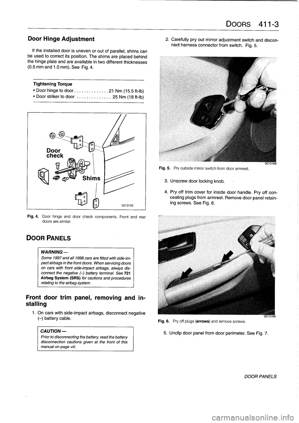
If
the
installed
door
is
uneven
or
out
of
parallel,
shims
can
be
used
to
correct
its
position
.
The
shims
are
placedbehind
the
hinge
plate
and
are
available
in
two
different
thicknesses
(0
.5
mm
and
1
.0
mm)
.
See
Fig
.
4
.
Tightening
Torque
"
Door
hinge
to
door
.............
..
21
Nm
(15
.5
ft-I
b)
"
Door
striker
to
door
...........
...
25
Nm
(18
ft-Ib)
DOOR
PANELS
0
l
o
0013102
Fig
.
4
.
Door
hinge
and
door
check
components
.
Front
and
rear
doors
are
similar
.
WARNING
-
Some
1997
and
all
1998
cars
are
fitted
with
side-im-
pact
airbags
in
the
front
doors
.
When
servicing
doors
on
cars
with
front
side-impact
airbags,
always
dis-
connect
the
negative
()
battery
terminal
.
See
721
Airbag
System
(SRS)
for
cautions
and
procedures
relating
to
the
airbag
system
.
Front
door
trimpanel,
removing
and
in-
stalling
1
.
On
cars
with
side-impact
airbags,
disconnect
negative
(-)
battery
cable
.
CAUTION
-
Prior
to
disconnecting
the
battery,
read
the
battery
disconnection
cautions
given
at
the
front
of
this
manual
on
page
viii
.
Fig
.
5
.
Pry
outside
mirror
switch
from
door
armrest
.
3
.
Unscrew
door
locking
knob
.
Fig
.
6
.
Pry
off
plugs
(arrows)
and
remove
screws
.
DOORS
411-
3
2
.
Carefully
pry
out
mirror
adjustment
switch
and
discon-
nect
harness
connector
from
switch
.
Fig
.
5
.
5
.
Unclip
door
panel
from
door
perimeter
.
See
Fig
.
7
.
0013168
4
.
Pry
off
trim
cover
for
insíde
door
handle
.
Pry
off
con-
cealing
plugs
from
armrest
.
Remove
door
panel
retain-
ing
screws
.
See
Fig
.
6
.
UU13169
DOOR
PANELS
Page 323 of 759
GENERAL
.
.
.
.
.
.
.
.
.
...
.
..
.
...
.
.........
510-1
Front
bumper
impact
absorber,
replacing
....
510-4
Rear
bumper,
removing
and
installing
.....
.510-4
OUTSIDE
REAR
VIEW
MIRRORS
.
...
.
.....
510-1
Rear
bumper
impact
absorber,
replacing
...
.
510-6
Outside
mirrorglass,
replacing
.
.
.........
510-1
Bumper
height,
adjusting
...
.
...
.
...
.
.
.
.
.
510-6
Outside
mirror
housing,
removing
and
installing
....
.
.....
.
.
.
.
.
.
510-1
EXTERIOR
TRIM
...
.
.
.
.
.
.
.
.
.
.
.
...
.
.
.
.
.
510-6
Outside
mirror,
removing
and
installing
.
.
.
.
.
510-2
BMW
embiem,
removing
and
installing
.
.
.
.
.
.
510-7
Body
side
molding,
replacing
.
.
.
.
.
.
.
.
.
.
.
.
.
510-7
BUMPERS
.
.
.
.
.
....
.
.....
.
.....
.
.
.
.
.
.
510-3
Radiator
grille,
removing
and
installing
.
.
.
.
.
.510-7
Front
bumper,
removing
and
installing
.
.
.
.
.
.
510-3
Front
panel,
removing
and
installing
...
.
.
.
.
.
510-7
GENERAL
510
Exterior
Trim,
Bumpers
This
repair
group
includes
repair
information
for
the
outside
rear
view
mirror,
front
and
rear
bumpers,
and
the
easily
re-
movable
exterior
trim
parts
.
OUTSIDE
REAR
VIEW
MIRRORS
The
remove
controlled
mirrors
come
in
two
styles
:
heated
and
unheated
.
Many
of
the
mirror
components
are
separately
available
from
an
authorized
BMW
dealer,
including
the
glass
and
outside
plastic
housing
.
Outside
mirror
glass,
replacing
CAUTION-
Mirror
shouldbe
ator
above
room
temperature
before
removal
.
Otherwise,
small
plastic
parts
or
glass
will
break
.
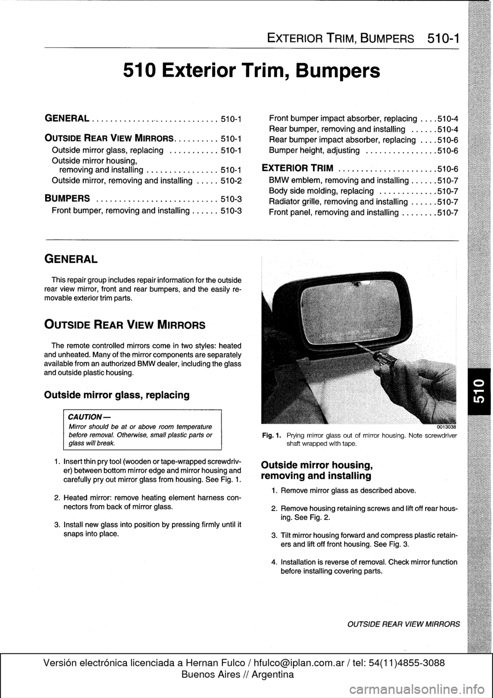
1
.
Insert
thin
pry
tool
(wooden
or
tape-wrapped
screwdriv-
er)
between
bottom
mirror
edge
and
mirror
housing
and
carefully
pry
out
mirror
glass
from
housing
.
See
Fig
.
1
.
2
.
Heated
mirror
:
remove
heating
element
harness
con-
nectors
from
back
of
mirror
glass
.
3
.
Install
new
glass
into
position
by
pressing
firmly
until
it
snaps
into
place
.
EXTERIOR
TRIM,
BUMPERS
510-1
00130
..
Fig
.1
.
Prying
mirror
glass
out
of
mirror
housing
.
Note
screwdriver
shaft
wrapped
with
tape
.
Outside
mirror
housing,
removing
and
installing
1
.
Remove
mirror
glass
as
described
above
.
2
.
Remove
housing
retaining
screws
and
lift
off
rear
hous-
ing
.
See
Fig
.
2
.
3
.
Tilt
mirror
housing
forward
and
compress
plastic
retain-
ers
and
lift
off
front
housing
.
See
Fig
.
3
.
4
.
Installation
is
reverse
of
removal
.
Check
mirror
function
before
installing
covering
parts
.
OUTSIDE
REAR
VIEW
MIRRORS
Page 324 of 759
510-2
EXTERIOR
TRIIVI,
BUMPERS
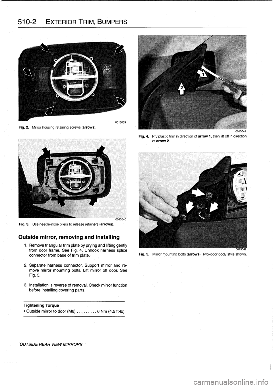
Fig
.
2
.
Mirror
housing
retaining
screws
(arrows)
.
Fig
.
3
.
Use
need1e-nose
pliers
to
release
retainers
(arrows)
.
Outside
mirror,
removing
and
installing
0013039
0013040
1
.
Remove
triangular
trim
plate
by
prying
and
lifting
gently
fromdoor
frame
.
See
Fig
.
4
.
Unhook
harness
splice
connector
from
base
of
trim
píate
.
2
.
Separate
harness
connector
.
Support
mirror
and
re-
move
mirror
mounting
bolts
.
Lift
mirror
off
door
.
See
Fig
.
5
.
3
.
Installation
is
reverse
of
removal
.
Check
mirror
function
before
installing
covering
parts
.
Tightening
Torque
"
Outside
mirror
to
door(M6)
..
.
..
.
..
.
6
Nm
(4
.5
ft-Ib)
OUTSIDE
REAR
VIEW
MIRRORS
0013041
Fig
.
4
.
Pry
plastictrim
in
direction
of
arrow
1,
then
lift
off
in
direction
of
arrow
2
.
0013042
Fig
.
5
.
Mirror
mounting
bolts
(arrows)
.
Two-door
body
style
shown
.
Page 429 of 759
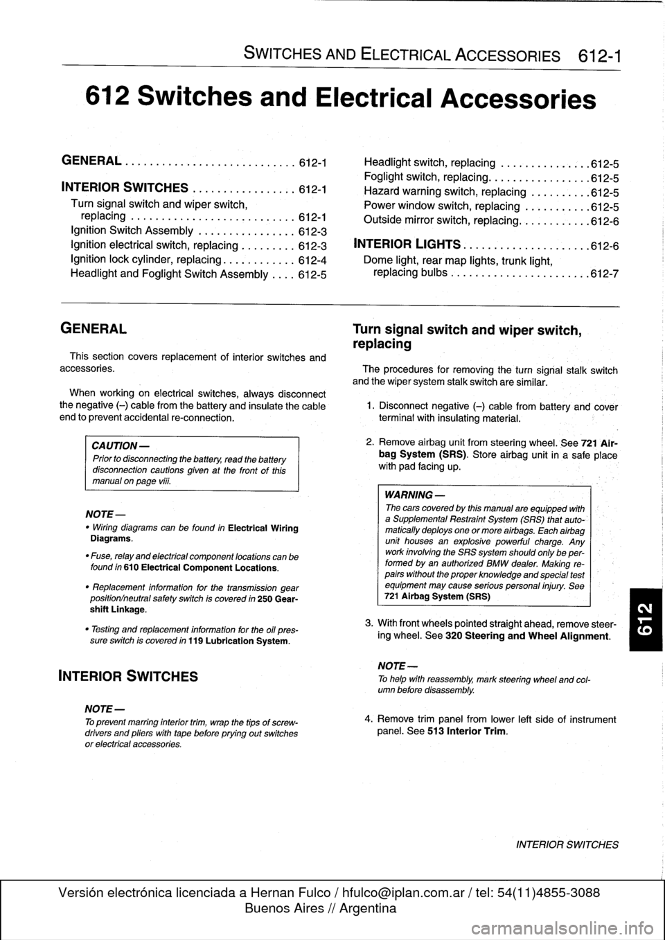
612
Switches
and
Electrical
Accessories
GENERAL
.
.
.
.
.
.
.
.
.
...
.
.
.
.
.
...
.
......
.612-1
Headlight
switch,
replacing
..
.
...
.
.
.
.
.
.
.
.
.
612-5
Foglight
switch,
replacing
....
.
.
.
.
.
.
.
.
.
.
.
.
.
612-5
INTERIOR
SWITCHES
.
.
...
.
.
.
.
.
.
.
.....
612-1
Hazard
warning
switch,
replacing
.
.
.
.
.
.
.
.
.
.612-5
Turn
signal
switch
and
wiper
switch,
Powerwindow
switch,
replacing
.
.
.
...
.
.
.
.
.
612-5
replacing
.
.
.
.
.
.
.
...
.
.
.
.....
.
....
.
.
.
.
612-1
Outside
mirrorswitch,
replacing
.
.
.
.
.....
.
.
.612-6
Ignition
Switch
Assembly
.
.
.
.
.
.
.
.
....
.
...
612-3
Ignition
electrical
switch,
replacing
.
...
.
....
612-3
INTERIOR
LIGHTS
.
.
................
.
..
612-6
Ignition
lock
cylinder,
replacing
.
.
.
.
.....
.
..
612-4
Dome
light,
rear
map
lights,
trunk
light,
Headlight
and
Foglight
Switch
Assembly
.
.
.
.
612-5
replacing
bulbs
.
......
.
.
.
.
.
.
.
.
.
.....
.
.612-7
GENERAL
Turn
signal
switch
and
wiper
switch,
replacing
Thissection
covers
replacement
of
interior
switches
and
accessories
.
The
procedures
for
removing
the
turn
signal
stalk
switch
and
the
wiper
system
stalk
switchare
similar
.
When
working
on
electrical
switches,
always
disconnect
the
negative
(-)
cable
from
the
battery
and
insulate
the
cable
end
to
prevent
accidental
re-connection
.
CAUTION-
Prior
to
disconnectiog
the
battery,
read
the
battery
disconnection
cautions
given
at
the
front
of
this
manual
on
page
viii
.
WARNING
-
The
cars
covered
by
this
manual
are
equipped
with
a
Supplemental
Restraint
System
(SRS)
that
auto-'
matically
deploys
one
or
more
airbags
.
Each
airbag
unit
houses
an
explosive
powerful
charge
.
Any
work
involving
the
SRS
system
should
only
be
per-
formed
byan
authorized
BMW
dealer
.
Making
re-
pairs
without
the
proper
knowledge
and
special
test
equipment
may
cause
serious
personal
injury
.
See
721
Airbag
System
(SRS)
3
.
With
front
wheels
pointed
straight
ahead,
remove
steer-
"
Testing
and
replacement
information
for
the
oil
ores-
¡ng
wheel
.
See
320
Steering
and
Wheel
Alignment
.
sure
switch
is
covered
in
119
Lubrication
System
.
NOTE-
"
Wirfng
diagramscan
be
found
in
Electrical
Wiring
Diagrams
.
"
Fuse,
relay
and
electrical
component
locations
can
be
found
in
610
Electrical
Component
Locations
.
"
Replacement
information
for
thetransmission
gear
position/neutral
safety
switch
is
covered
in
250
Gear-
shift
Unkage
.
INTERIOR
SWITCHES
NOTE
-
To
preventmarring
interior
trim,
wrap
the
tips
of
screw-
drivers
and
pliers
with
tape
beforeprying
out
switches
or
electrical
accessories
.
SWITCHES
AND
ELECTRICAL
ACCESSORIES
612-1
1
.
Disconnect
negative
(-)
cable
from
battery
and
cover
terminal
with
insulating
material
.
2
.
Remove
airbag
unit
from
steering
wheel
.
See
721
Air-
bag
System
(SRS)
.
Store
airbag
unit
in
a
safe
placew¡th
pad
facing
up
.
NOTE
-
To
helo
with
reassembly,
mark
steering
wheel
and
col-
umn
before
disassembly
.
4
.
Remove
trim
panel
from
lower
left
side
of
instrument
panel
.
See513
Interior
Trim
.
INTERIOR
SWITCHES
Page 434 of 759
612-6
SWITCHES
AND
ELECTRICAL
ACCESSORIES
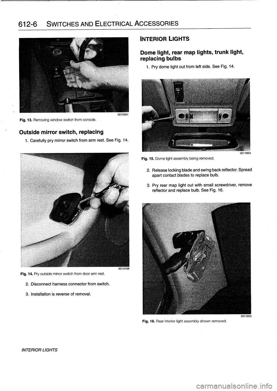
Fig
.
13
.
Removing
window
switch
from
console
.
Outside
mirror
switch,
replacing
0012561
1
.
Carefully
pry
mirror
switch
from
arm
rest
.
See
Fig
.
14
.
Fig
.
14
.
Pry
outside
mirror
switch
from
door
arm
rest
.
2
.
Disconnectharness
connector
from
switch
.
3
.
Installation
is
reverseof
removal
.
INTERIOR
LIGHTS
0013168
INTERIOR
LIGHTS
Dome
light,
rear
map
lights,
trunk
light,
replacing
bulbs
1
.
Pry
dome
light
out
from
left
side
.
See
Fig
.
14
.
Fig
.
15
.
Dome
light
assembly
being
removed
.
2
.
Release
locking
blade
and
swing
back
reflector
.
Spread
apart
contact
blades
toreplace
buib
.
3
.
Pry
rear
map
light
out
with
small
screwdriver,
remove
reflector
and
replace
bulb
.
See
Fig
.
16
.
Fig
.
16
.
Rear
interior
light
assembly
shown
removed
.
0011855
Page 753 of 759
4
INDEX
Evaporator
See
Air
conditioning
EWS
(Electronic
immobilization
system)
515-8
Exhaust
system
See
also
Maintenance
program
general
information
180-1
exhaust
manifolds,
removingAnstalling
180-5
exhaustsystem,
removing/installing
180-3
Expansion
valve
See
Air
conditioning
Exterior
lighting
general
information
630-1
center
brake
light
housing,
replacing
(4-door
and
coupe
models)
630-5
foglight
assembly,
removing/installing
630-3
front
turn
signal
assembly,
removing/
installing
630-4
headlight
assembly,removing/
installing
630-2
headlight
bulb,
replacing
630-1
license
plate
light,
removing/installing
630-6
side
marker
lights
630-4
taillight
assembly,
removing/installing
630-5
taillight
bulbs,
replacing
630-4
Exterior
trim,
bumpers
general
information
510-1
BMW
embiem,
removing/installing
510-7
body
side
molding,
replacing
-7
bumper
height,
adjusting
510-6
front
bumper,
removing/installing
510-3
front
bumper
impact
absorber,
replacing
510-4
front
panel,
removing/installing
510-7
outside
rear
view
mirrors
510-1
mirror
housing,
removing/installing
510-1
mírror,
removing/installing
510-2
mirror
glass,
replacing
510-1
radiator
grille,
removing/installing
510-7
rear
bumper,
removingfinstalling
510-
4
rear
bumper
impact
absorber,
replacing
510-4
F
Fenders,
engine
hood
general
information
410-1
front
fenders
410-1
front
fender,
removing/installing
410-1
hood
aligning
410-4
hood,
raising
to
service
position
410-2
hood
release
cable
and
latches,
adjusting
410-4
hood,
removing/installing
410-3
Finaldrive
general
information
331-1
final
drive
se
rvice
331-1
flange
oil
sea¡,
replacing
331-2
inputshaft
oil
sea¡,
replacing
331-3
oil,
draining/filling
331-1
oil
seals331-1
removing/installing
331-3
Final
drive
carrier
See
Rear
suspension
Firing
order
See
Ignition
system
Flexdisc
See
DriveshaftFluids
and
lubricants
See
Maintenance
program
Foglight
See
Exterior
lighting
Front
suspension
general
information
310-1
ball
joint
See
outer
control
arm
ball
joint
control
arm,
removing/installing
310-5
control
arm
bushing,
replacing
310-7
control
arms
310-5
front
wheel
bearing,
replacing
310-8
front
wheel
bearings
310-8
outer
control
arm
ball
joint,
replacing
(except
M3)310-6
ride
height
310-4shock
absorbers
and
springs
310-2
stabilizer
bar
310-9
stabilizer
bar,
removing/installing
310-9
strut
assembly,disassembling/
assembling310-4
strut
assembly,
removing/installing
310-2subframe
crossmember
310-9subframe
crossmember,
removing/
installing
310-9
Fuel
injection
general
information
130-2
basic
engine
settings
130-2
principies
of
operatínn
130-2
Bosch
DME
Ml
.7
component
tests
and
repairs
130-14
air
floiv
sensor,testing/replacing
130-14
engine
coolant
temperature
(ECT)
sensor,
testing/replacing
130-15
¡dle
speed
control
valve,
testing/
replacing
130-16
throttle
position
sensor
(TPS),
testing/replacing
130-16
Bosch
DME
M3
.1
and
M3
.3
.1
component
tests
and
repairs
130-17
engine
coolant
temperature
(ECT)
sensor,
testing/replacing
130-18
¡dle
speed
control
valve,
replacing
130-21
¡dle
speed
control
valve,
testing
130-
20
intake
air
temperature
(IAT)
sensor,
testing/replacing
130-19
mass
air
flow
sensor130-17
Bosch
DME
M3
.1
and
M3
.3.1
(cont)
mass
air
flow
sensor
(hot
film)
testing/replacing
130-18
mass
air
flow
sensor
(hot
wire)
testing/replacing
130-17
throttle
position
sensor
(TPS),
testing/replacing
130-19
Bosch
DME
M5
.2
component
replacement
130-21engine
coolant
temperature
(ECT)
sensor,
replacing
130-22
ldle
speed
control
valve,
replacing
130-23
intake
air
temperature
(IAT)
sensor,
replacing
130-22
mass
air
flow
sensor,
replacing
130-
22
throttle
position
sensor
(TPS),
replacing
130-22
DISA
(dual
resonance
intake
system)
130-3
ECM
pin
assignments130-26
electrical
checks
andcomponent
testing
130-7engine
control
module(ECM),
accessing
130-26
fuel
delivery
tests
130-9
fuel
pressure
regulator
response
to
engine
load,
testing
130-11
fuel
pressure
regulator
130-13
fuel
pressure
regulator,
replacing
(fuel
rail
mount)130-13
fuel
pressure
regulator,
replacing
(under
car
mount)130-14
fuel
pump
relay,
testing
130-7
fuel
rail
and
injectors,
checking
130-11
fuel
rail
and
injectors,
replacing
130-
12
fuel
delivery
tests
(cont
.)
operatíng
fuel
pump
for
tests
130-9
relieving
fuel
pressure
and
connecting
fuel
pressure
gauge
130-10
residual
fuel
pressure,
testing
130-10
main
relay,
testing
130-7on-board
diagnostics
(OBD)
and
fault
diagnosis
130-4
oxygen
sensor,
testing
(Bosch
systems
only)
130-8
secondary
air
injection
130-5
Siemens
MS
41
.1
component
replacement
130-23
engine
coolant
temperature
(ECT)
sensor,
replacing
130-25
¡dle
speed
control
valve,
replacing
130-26
lntake
air
temperature
(IAT)
sensor,
replacing
130-25
mass
air
flow
sensor,
replacing
130-
25
throttle
position
sensor
(TPS),
replacing
130-26warnings
and
cautions
130-6
Fuel
filter
See
Maintenance
program
Page 757 of 759
8
INDEX
Speakers
See
Radio
SRS
(Supplemental
restraint
system)
See
Airbag
system
(SRS)
Starter
See
Battery,
starter,
alternator
Steering
and
wheel
alignment
general
information
320-1
caster
and
camber
320-5
front
toe-in
and
toe
difference
angle
320-6
outer
tie
rod
end,
replacing
320-4
power
steering
pump,
removing/
installing
320-2
power
steering
system
320-2
power
steering
system,
bleeding/filling
320-3
rear
toe-in
320-6
steering
gear320-3
steering
gear
rack,
removing/installing
320-3
steering
wheel
320-1
steering
wheel,
removing/installing
320-1
tie
rod,
replacing
320-5
wheel
alignment
320-5
wheel
alignment
specifications
320-6
Steering
gear
See
steering
and
wheel
alignment
Strut
See
Front
suspension
Subframe
See
Front
suspension
Sunroof
general
information
540-1
motor,
removing/installing
540-3
panel,
adjusting
540-2
panel,
emergency
closing
540-2
Suspension,
front
See
Front
suspension
Suspension,
rear
See
Rear
suspension
Suspension,
steering
and
brakes
general
information
300-1
al¡
season
traction
(AST)
300-4
antilock
brake
system
(ABS)
300-2
brakes
300-2
front
suspension
300-1
integrated
systems
300-2
M3
suspension
and
brakes
300-7
steering
300-2
rear
suspension
300-2suspension
and
steering
troubleshooting
300-7
tires
and
wheels300-2
T
Switches
and
electrical
accessories
general
information
612-1
dome
light,
rear
map
lights,
trunk
light,
replacing
bulbs
612-7
hazard
warning
switch,
replacing
612-5
headlight
switch,
replacing
612-5
foglight
switch,
replacing
612-5
ignition
electrical
switch,
replacing
612-3
ignition
lock
cylinder,
replacing
612-4
ignition
switch
assembly
612-3
outside
mirror
switch,
replacing
612-6
power
window
switch,
replacing
612-5
turn
signal
switch
and
wiper
switch,
removing/installing
612-1
wiper
switch
See
turn
signal
and
wiper
switch
Taillight
See
Exterior
lighting
Thermostat
See
Cooling
system
Throttleposition
sensor
(TPS)
See
Fuel
injection
Throw-out
bearing
See
ClutchTierod
See
Steering
and
wheel
alignment
Tires
See
Suspension,
steering
and
brakes-general
See
also
Maintenance
program
Timing
chain
See
Camshaft
timing
chain
Toe-in
See
Steering
and
wheel
alignment
Tools
See
Fundamentals
for
the
do-it-
yourself
owner
Torque
convector
See
Automatic
transmission
Towing
See
Fundamentals
for
the
do-it-
yourself
owner
Traction
control
See
also
Suspension,
steering
and
brakes-general
Trailing
arm
See
Rear
suspension
Transmission-general
See
also
Automatic
transmission
See
also
Manual
transmission
general
information
200-1
automatic
transmission
200-1
manual
transmission
200-1
transmission
ID
codes
200-2
Transmission
fluid
See
Maintenance
program
See
also
Automatic
transmission
Transmission
input
shaft
See
Manual
transmission
Transmission
output
shaft
See
Manual
transmission
Trim,
interior
See
Interior
trim
Trunk
lid
general
information
412-1
trunk
lid,
412-1
trunk
lid,
aligning
412-1
trunk
lid,
removing/installing
412-1
trunk
lid
support
strut,
removing/
installing
412-2
U
Upholstery
See
Maintenance
program
U-joints
See
Driveshaft
V
V-belt
See
Maintenance
program
Vacuum
booster
See
Brakes
Vacuum
leaks
See
Engine-general
Valveguides
See
Cylinder
head
and
valvetrain
Valve
seals
See
Cylinder
head
and
valvetrain
Valveseats
See
Cylinder
head
and
valvetrain
Valves
See
Cylinder
head
and
valvetrain
Valvetrain
See
Cylinder
head
and
valvetrain
VANOS
(variable
valve
timing)
See
Camshaft
timing
chaín
See
also
Engine-general
Vehicle
identification
number
(VIN)
See
Fundamentals
for
the
do-it-
yourself
owner
Vehicle
speed
sensor
See
Instruments
Ventilation
See
Air
conditioning
See
also
Heating
Voltage
regulator
See
Battery,
starter,
alternator
Voltage
tests
See
Electrical
system-general
W
Warnings
vi¡
Washer
fluid
pump
See
Wipers
and
washers
Washers
See
Wipers
and
washers
Water
pump
See
Cooling
system
Waxing
See
Maintenance
program