speed sensor BMW M3 1994 E36 Owner's Guide
[x] Cancel search | Manufacturer: BMW, Model Year: 1994, Model line: M3, Model: BMW M3 1994 E36Pages: 759
Page 233 of 759
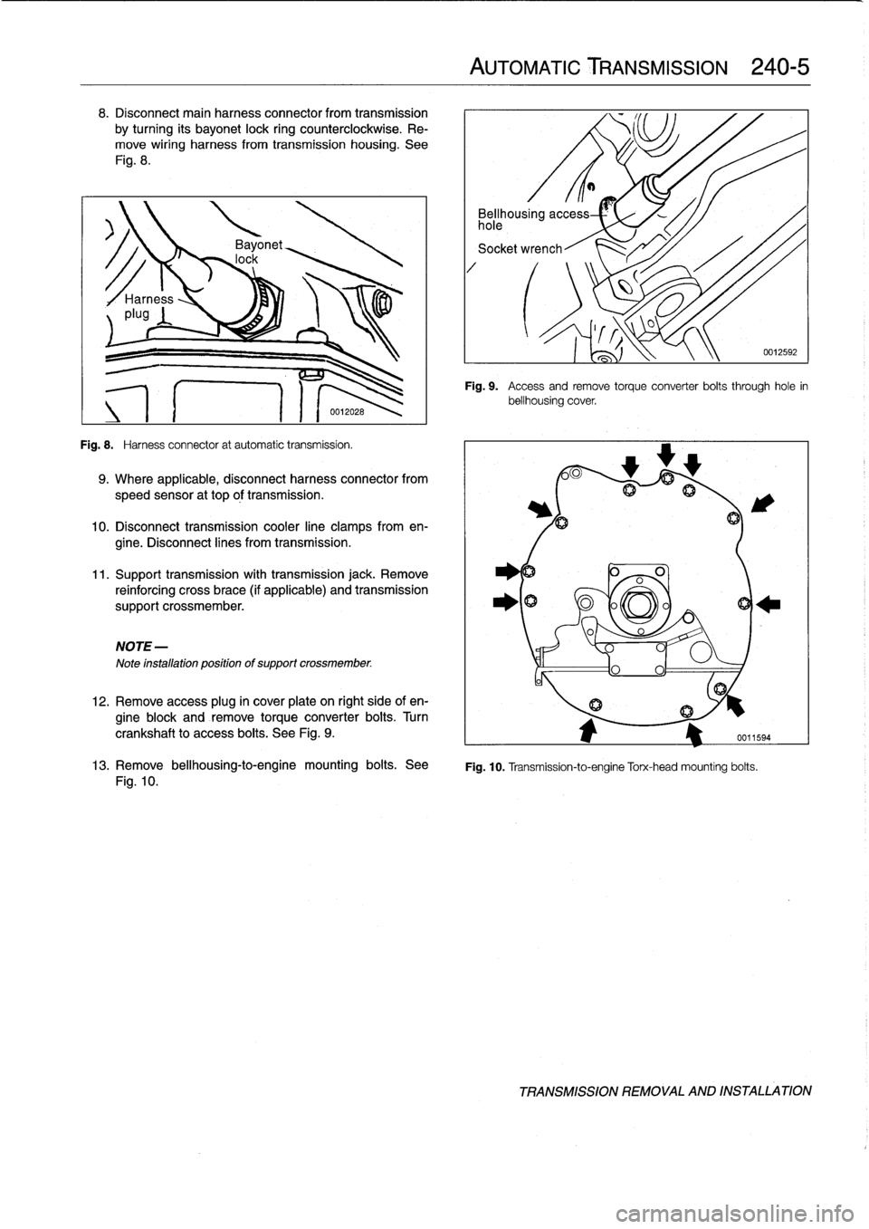
8
.
Disconnect
main
harness
connector
from
transmission
by
turning
its
bayonet
lock
ring
counterclockwise
.
Re-
move
wiring
harness
from
transmission
housing
.
See
Fig
.
8
.
Fig
.
8
.
Harness
connector
at
automatic
transmission
.
9
.
Where
applicable,
disconnect
harness
connector
from
speed
sensor
at
top
óf
transmission
.
10
.
Disconnect
transmission
cooler
line
clamps
from
en-
gine
.
Disconnect
lines
from
transmission
.
11
.
Support
transmission
with
transmission
jack
.
Remove
reinforcing
cross
brace
(if
applicable)
and
transmission
support
crossmember
.
NOTE-
Note
installation
positionof
support
crossmember
.
12
.
Remove
access
plug
in
cover
plate
on
right
side
of
en-
gine
block
and
remove
torqueconverter
bolts
.
Turn
crankshaft
to
access
boits
.
See
Fig
.
9
.
AUTOMATIC
TRANSMISSION
240-
5
Bellhousing
access
hole
Socket
wrench
Fig
.
9
.
Access
andremove
torque
converter
boits
through
hole
in
bellhousing
cover
.
0
A
fij
13
.
Remove
bellhousing-to-engine
mounting
bolts
.
See
Fig
.
10
.
Transmission-to-engine
Torx-head
mounting
bolts
.
Fig
.
10
.
0012592
TRANSMISSION
REMOVAL
AND
INSTALLATION
Page 250 of 759
300-2
SUSPENSION,
STEERING
AND
BRAKES-GENERAL
Steering
INTEGRATED
SYSTEMS
The
steering
linkage
connects
the
rack-and-pinion
unit
through
tie
rodsto
the
steering
arms
.
The
tie
rod
ends
allow
the
wheels
to
pivot
and
react
to
suspension
travel
.
Rear
Suspension
The
rear
axle
carrier
is
the
main
mounting
point
for
the
final
drive
housing
and
the
rear
suspension
components
.
Trailing
arms
locatethe
rear
wheels
and
anchorthe
springs,
shocks
and
stabilizer
bar
.
Driveaxies
with
constant-velocity
(CV)
joints
at
both
ends
transfer
power
from
the
differential
to
the
road
wheels
.
The
differential
is
mounted
to
the
rearaxle
carrier
through
rubber
mountsand
bushings
to
hele
isolate
drivetrain
noise
and
vibration
.
Brakes
E36
cars
areequipped
with
power
disc
brakes
with
an
inte-
gral
antilock
brakes
(ABS)
.
The
parking
brake
is
a
dual-drum
system
integrated
with
the
rear
brake
rotors
.
See
Fig
.
3
.
Power
assist
is
provided
by
a
vacuum
booster
when
the
en-
gine
is
running
.
The
brakepedal
pushrod
is
connected
directly
to
the
master
cylinder,
so
failure
of
the
vacuum
booster
does
not
normally
result
in
total
brake
failure
.
0012124
Each
disc
brakeuses
a
caliper
with
a
single
hydraulic
cylin-
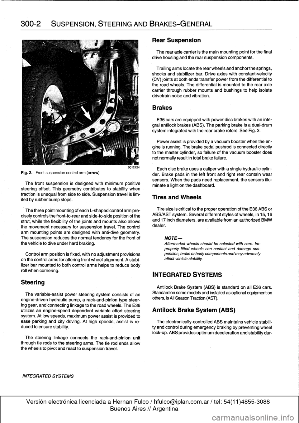
Fig
.
2
.
Front
suspension
control
arm
(arrow)
.
der
.
Brake
pads
in
the
left
front
and
right
rear
contain
wear
sensors
.
When
the
padsneed
replacement,the
sensors
illu-
The
front
suspension
is
designed
with
minimum
positive
minate
a
light
on
the
dashboard
.
steering
offset
.
This
geometry
contributes
to
stability
when
traction
is
unequalfrom
side
to
side
.
Suspension
travel
is
lim-
Tires
and
Wheels
ited
by
rubber
bump
stops
.
The
three
point
mounting
of
each
L-shaped
control
arm
ere-
Tiresize
is
critica¡
to
the
proper
operatíon
of
the
E36
ABS
or
cisely
controls
the
front-to-rear
and
side-to-side
position
of
the
ABS/AST
system
.
Severa¡
different
styles
of
wheels,
in
15,16
strut,
while
the
flexibility
of
the
joints
and
mounts
alsoallows
and
17
inch
diameters,
are
available
from
an
authorized
BMW
the
movement
necessary
for
suspension
travel
.
The
control
dealer
.
arm
mounting
points
are
designed
with
anti-dive
geometry
.
The
suspension
reduces
the
normaltendency
for
the
front
of
NOTE-
the
vehicle
to
dive
under
hard
braking
.
Aftermarket
wheelsshould
be
selected
wlth
care
.
Im-
properly
fitted
wheels
can
contact
anddamage
sus
Control
arm
position
is
fixed,
with
no
adjustment
provisions
pension,
brakeorbodycomponentsandmayadversely
on
the
control
arms
for
alter¡ng
front
wheel
al
ignment
.
A
stabi-
affect
vehicle
stability
.
lizer
bar
mounted
to
both
control
arms
heles
to
reduce
body
rol¡
whencomering
.
INTEGRATED
SYSTEMS
Antilock
Brake
System
(ABS)
is
standard
on
all
E36
cars
.
The
variable-assist
power
steering
system
consists
of
an
Standard
on
some
models
and
installed
as
optional
equipment
on
engine-driven
hydraulic
pump,
a
rack-and-pinion
type
steer-
others,
is
All
Season
Traction
(AST)
.
ing
gear,
and
connecting
linkage
to
the
road
wheels
.
TheE36
utilizes
an
engine-speed
dependent
variable
effort
steering
Antilock
Brake
System
(ABS)
system
.
At
low
speeds,
maximum
power
assist
is
provided
to
ease
parking
and
city
driving
.
Athigh
speeds,
assist
is
re-
The
electronically-controlled
ABS
maintains
vehícle
stabili
duced
to
ensure
stability
.
ty
and
control
during
emergency
braking
by
preventing
wheel
lock-up
.
ABS
provides
optimum
deceleration
and
stability
dur-
Page 251 of 759
Wheel
brake
caliper
Electronic
control
module
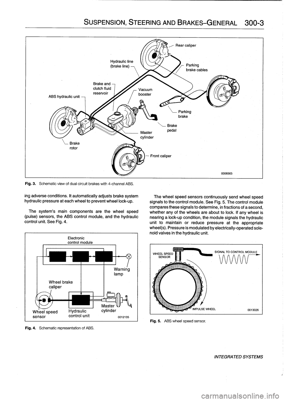
Fig
.
4
.
Schematic
representation
of
ABS
.
SUSPENSION,
STEERING
ANDBRAKES-GENERAL
300-3
Fig
.
3
.
Schematic
view
ofdual
circuit
brakes
with
4-channel
ABS
.
ing
adverse
conditions
.
It
automatically
adjusts
brake
system
hydraulic
pressure
at
each
wheel
to
prevent
wheel
lock-up
.
The
system's
main
components
arethe
wheel
speed
(pulse)
sensors,
the
ABS
control
module,
and
the
hydraulic
control
unit
.
See
Fig
.
4
.
Warning
lamp
u
Master
Whee
_
l
speed
I-lydraulic
cylinder
sensor
control
unit
0012135
UNI
The
wheel
speed
sensors
continuously
send
wheel
speed
signals
to
the
control
module
.
See
Fig
.
5
.
The
control
module
compares
these
signals
to
determine,
in
fractions
of
a
second,
whether
any
of
the
wheels
areabout
to
lock
.
If
any
wheel
is
nearing
a
lock-up
condition,
the
module
signals
the
hydraulic
unit
to
maintain
or
reduce
pressure
at
the
appropriatewheel(s)
.
Pressure
is
modulated
by
electrically-operated
sole-
noid
valves
in
the
hydraulic
unit
.
Fig
.
5
.
ABS
wheelspeed
sensor
.
0006563
INTEGRATED
SYSTEMS
Page 252 of 759
300-4
SUSPENSION,
STEERING
AND
BRAKES-GENERAL
Three-channel
ABS
ís
used
on
al[
E36
cars
equipped
with
Al¡
Season
Traction
(AST)
standard
ABS
.
Each
front
wheelhas
a
separate
solenoid
valve
to
modulate
hydraulic
pressure
to
that
brake
caliper
.
The
traction
control
system
works
in
conjunction
with
ABS
The
rear
wheels
are
modulated
asa
pair,
controlled
by
a
sin-
and
the
engine
management
system
to
enhance
vehicle
con
gle
solenoid
valve
.
trol
.
The
main
function
of
the
AST
system
is
to
maintain
the
rolling
contact
between
the
tires
and
the
road
surface
under
al¡
driving
E36
cars
equipped
with
ABS/AST
utilize
a
four
channel
sys-
conditions
.
This
is
achieved
through
exact
application
and
tem,
which
functionsexactly
as
the
three
channelsystem
management
of
braking
and
drivetrain
forces
.
above,except
that
the
rear
wheels
are
modulated
individually
.
IDLE
SPEED
CONTROL
VALVE
HROTTLE
PLATE
6
.
Í
III
i
ADS
ACTU
AT
OR
THROTTLE
PLATE
POSITION
SENSOR
DME
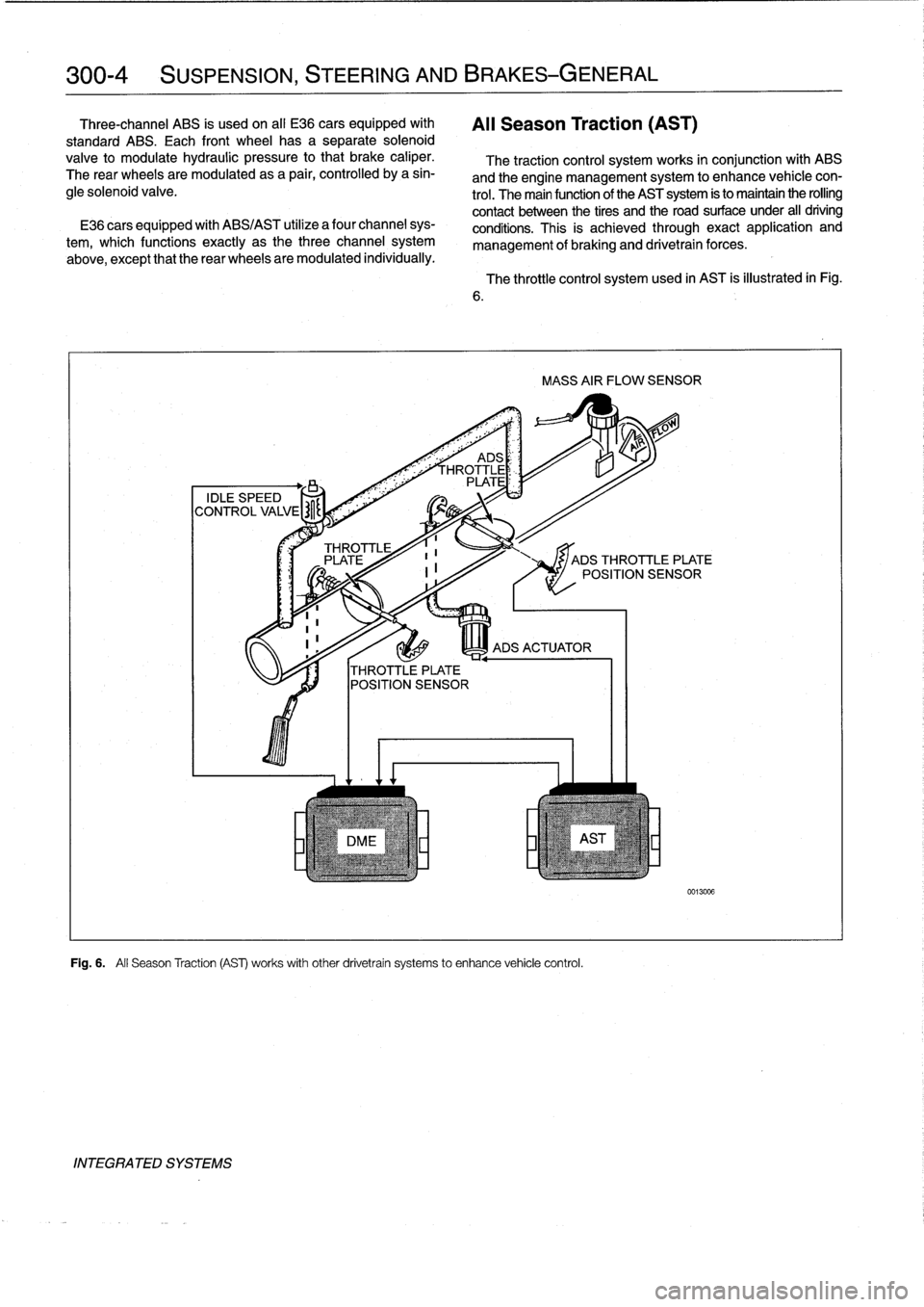
Fig
.
6
.
All
Season
Traction
(AS)
works
withother
drivetrain
systems
to
enhance
vehicle
control
.
INTEGRATED
SYSTEMS
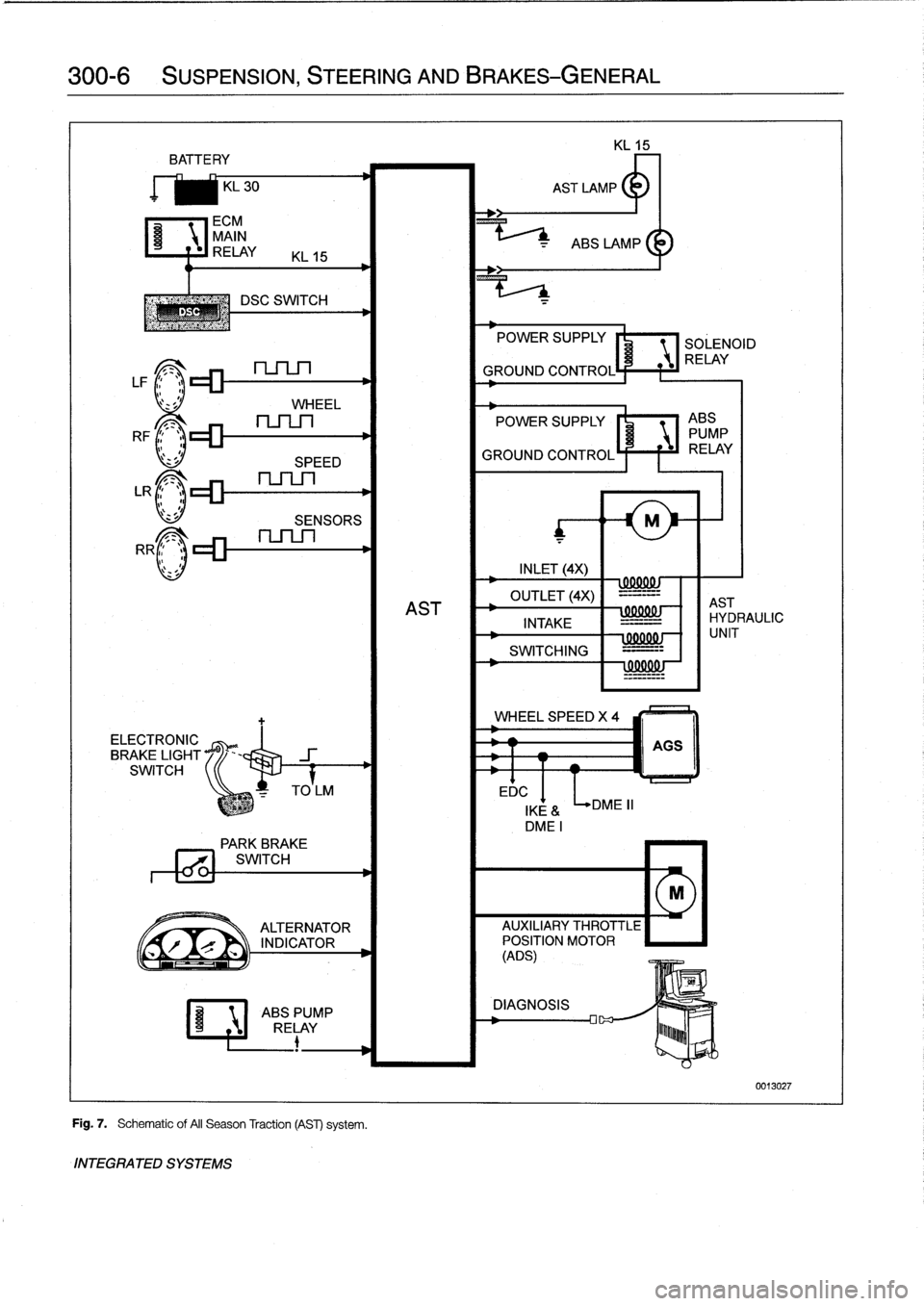
The
throttle
control
system
used
in
AST
is
illustrated
in
Fig
.
MASS
AIR
FLOW
SENSOR
JADS
THROTTLE
PLATE
POSITION
SENSOR
0013006
Page 254 of 759
300-6
SUSPENSION,
STEERING
AND
BRAKES-GENERAL
BATTE
RY
KL
30
ECM
MAIN
C~
RELAY
KL
15
DSC
SWITCH
LF1
;1~lZZ~
nSLn
l'
z
sJ
WHEEL
RF
c_
.
LR
r_
.
>
RR
ELECTRONIC
BRAKE
LIGHT
SWITCH
SPEED
SENSORS
Fig
.
7
.
Schematic
of
AII
Season
Traction
(AST)
system
.
INTEGRATED
SYSTEMS
EDC
POWER
SUPPLY
SOLENOID
RELAY
GROUND
CONTROL
POWER
SUPPLY
I'
1
ABS
PUMP
GROUND
CONTROLÍ
F
f
iJ
RELAY
INLET
(4X)
wxxuw
OUTLET
(4X)
-=-=--
AST
AST
INTAKE
IHYDRAULIC
-
=-
SWITCHING
=---
!
99001
!J
WHEEL
SPEED
X
4
DME
II
000001
-
f
1
UNIT
AGS
IKE
&
DMEI
PARK
BREVE
771
SWITCH
M
ALTERNATOR
AUXILIARY
THROTTLE
r
`
INDICATOR
POSITION
MOTOR
(ADS)
ABSPUMP
DIAGNOSIS
RELAY
lu~~~b
0013027
Page 258 of 759
310-2
FRONT
SUSPENSION
WARNING-
"
Physical
safety
could
be
impaired
if
procedures
described
here
areundertaken
without
the
proper
service
tools
and
equipment
.
Be
sure
to
have
the
right
tools
onhand
before
beginning
any
job
.
"
Do
notreuse
self-locking
nuts
or
bolts
.
They
are
designed
to
beused
only
once
and
may
fail
if
re-
used
.
Always
replace
self-locking
fasteners
any
timethey
are
loosenedor
removed
.
"
Do
not
install
bolts
and
nuts
coated
with
under-
coating
wax,
as
the
correct
tightening
torque
can-
not
beassured
.
Always
clean
the
threads
with
solventbefore
installation,
or
install
new
parts
.
"
Do
not
attempt
to
weld
or
straighten
any
suspen-
sion
components
.
Replace
damaged
parts
.
SHOCK
ABSORBERS
AND
SPRINGS
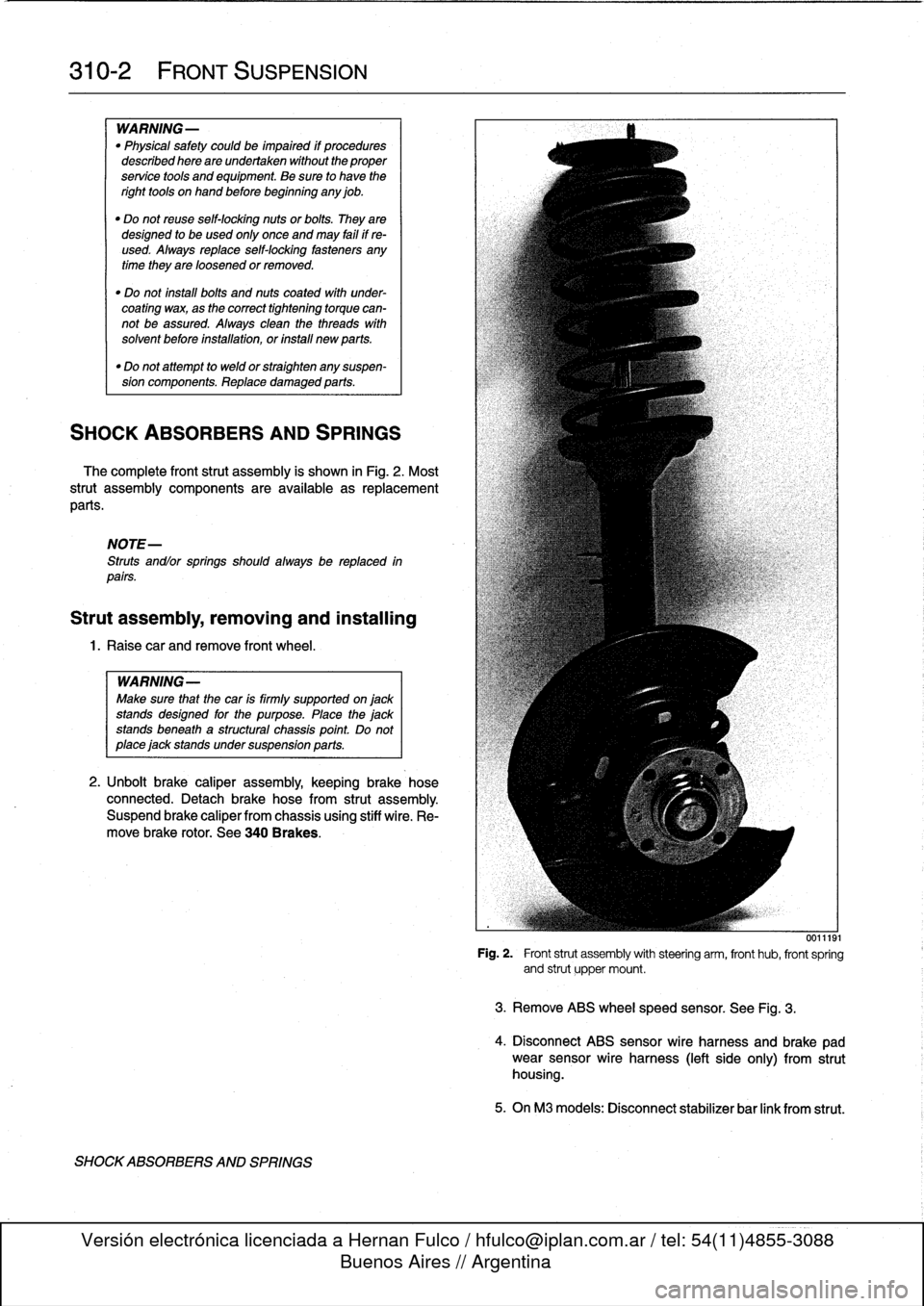
The
complete
front
strut
assembly
is
shown
in
Fig
.
2
.
Most
strut
assembly
components
are
available
asreplacement
parts
.
NOTE-
Struts
andlor
springs
shouldalways
be
replaced
in
parts
.
Strut
assembly,
removing
and
installing
1
.
Raisecar
and
remove
front
wheel
.
WARNING-
Make
sure
that
the
car
is
firmly
supported
on
jack
standsdesigned
for
the
purpose
.
Place
the
jack
standsbeneath
a
structural
chassis
point
Do
not
place
jack
stands
under
suspension
parts
.
2
.
Unbolt
brake
caliper
assembly,
keepingbrake
hose
connected
.
Detach
brake
hose
from
strut
assembly
.
Suspend
brake
caliper
from
chassis
using
stiff
wire
.
Re-
move
brake
rotor
.
See
340
Brakes
.
SHOCKABSORBERS
AND
SPRINGS
0011191
Fig
.
2
.
Front
strut
assembly
with
steering
arm,
front
hub,
front
spring
and
strut
upper
mount
.
3
.
Remove
ABS
wheelspeed
sensor
.
See
Fig
.
3
.
4
.
Disconnect
ABS
sensor
wire
harness
and
brake
pad
wear
sensor
wire
harness
(left
side
only)
from
strut
housing
.
5
.
OnM3
modeis
:
Disconnect
stabilizer
bar
link
from
strut
.
Page 259 of 759
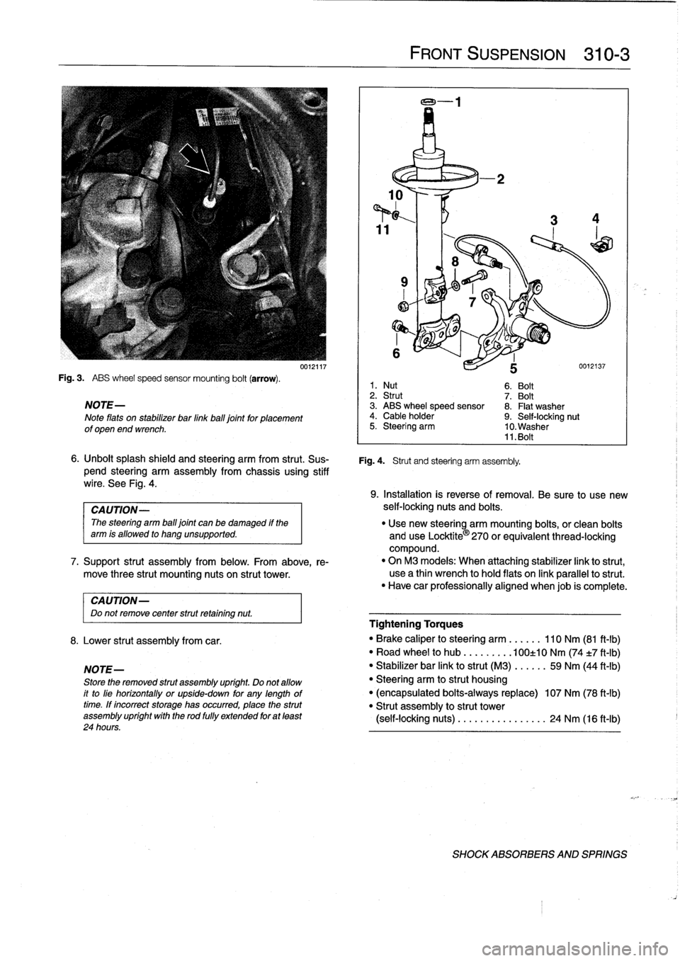
Fig
.
3
.
ABS
wheel
speed
sensor
mounting
bolt
(arrow)
.
NOTE-
Note
flats
on
stabilizer
bar
linkball
joint
for
placement
of
open
end
wrench
.
CAUTION-
Do
not
remove
center
strut
retaining
nut
.
8
.
Lower
strut
assembly
from
car
.
NOTE-
Store
the
removed
strut
assembly
upríght
.
Do
not
allow
it
to
líe
horizontally
or
upside-down
for
any
lengthoftime
.
If
íncorrect
storage
has
occurred,
place
the
strut
assembly
upríght
wíth
the
rod
fully
extended
for
at
least
24
hours
.
0012117
FRONT
SUSPENSION
310-3
6
.
Unbolt
splash
shield
and
steering
arm
from
strut
.
Sus-
Fig
.
4
.
Strut
and
steering
arm
assembly
.
pend
steering
arm
assembly
from
chassis
using
stiff
wire
.
See
Fig
.
4
.
1
.
Nut
6
.
Bolt
2
.
Strut
7
.
Bolt
3
.
ABS
wheel
speed
sensor
8
.
Flat
washer
4
.
Cable
holder
9
.
Self-locking
nut
5
.
Steering
arm
10
.
Washer
11
.
Bolt
9
.
Installation
is
reverse
of
removal
.
Be
sure
to
use
new
CAUTION-
self-locking
nuts
and
bolts
.
The
steering
arm
ball
joint
can
be
damaged
if
the
"
Use
new
steering
arm
mounting
bolts,
or
clean
bolts
arm
is
allowed
to
hang
unsupported
.
and
use
Locktite
®
270
orequivalent
thread-locking
compound
.
7
.
Support
strut
assembly
from
below
.
From
above,
re-
"
On
M3
models
:
When
attaching
stabilizer
link
to
strut,
move
three
strut
mounting
nuts
on
strut
tower
.
use
a
thin
wrench
to
hold
flats
on
link
parallelto
strut
.
"
Have
car
professionally
aligned
When
job
is
complete
.
Tightening
Torques
"
Brake
caliper
to
steering
arm
......
110
Nm
(81
ft-lb)
"
Road
wheel
to
hub
.........
100±10
Nm
(74
t7
ft-Ib)
"
Stabilizer
bar
link
to
strut
(M3)
.....
.
59
Nm
(44
ft-lb)
"
Steering
arm
to
strut
housing
"
(encapsulated
bolts-always
replace)
107
Nm
(78
ft-lb)
"
Strut
assembly
to
strut
tower
(self-locking
nuts)
........
...
..
..
.
24
Nm
(16
ft-Ib)
SHOCK
ABSORBERS
AND
SPRINGS
Page 264 of 759
310-
8
FRONT
SUSPENSION
FRONT
WHEEL
BEARINGS
The
front
wheel
bearings
are
permanently
sealed
and
re-
quire
no
maintenance
.
The
bearing
is
integral
with
the
wheel
hub
and
pressed
onto
the
steering
arm
stub
axle
.
Special
press
tools
are
requiredto
replace
the
front
wheel
bearings
.
Read
the
procedure
through
before
beginning
the
job
.
Front
wheel
bearing,
replacing
1
.
Raise
car
and
remove
wheel
.
WARNING-
Make
sure
that
the
car
is
firmly
supportedon
jack
stands
designed
for
the
purpose
.
Place
the
jack
stands
beneatha
structural
chassis
point
.
Do
not
place
jack
stands
under
suspension
parts
.
2
.
Pry
off
dust
cap
from
centerof
wheel
hub
.
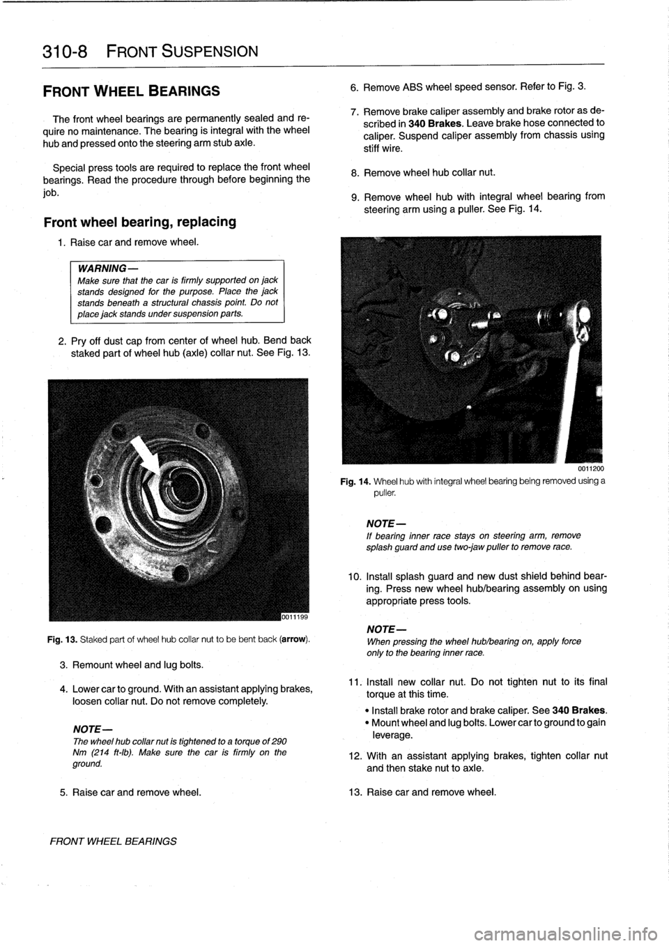
Bend
back
staked
part
of
wheel
hub
(axle)
collar
nut
.
See
Fig
.
13
.
Fig
.
13
.
Staked
part
of
wheel
hub
collar
nut
to
be
bent
back
(arrow)
.
3
.
Remount
wheel
and
lug
bolts
.
4
.
Lower
canto
ground
.
With
an
assistant
applying
brakes,
loosen
collar
nut
.
Do
not
remove
completely
.
NOTE-
The
wheel
hub
collar
nut
is
tightened
to
a
torque
of
290
Nm
(214
ft-Ib)
.
Make
sure
the
car
is
firmly
on
the
ground
.
FRONT
WHEEL
BEARINGS
6
.
Remove
ABS
wheel
speed
sensor
.
Refer
to
Fig
.
3
.
7
.
Remove
brake
caliper
assembly
and
brake
rotor
as
de-
scribed
in
340
Brakes
.
Leave
brakehose
connected
to
caliper
.
Suspend
caliper
assembly
from
chassis
using
stiff
wire
.
8
.
Remove
wheel
hub
collar
nut
.
9
.
Remove
wheel
hub
with
integral
wheel
bearing
from
steering
arm
using
a
puller
.
See
Fig
.
14
.
0011200
Fig
.
14
.
Wheel
hub
with
integral
wheel
bearing
being
removed
using
a
puller
.
NOTE-
If
bearing
inner
race
stays
on
steering
arm,
remove
splash
guard
and
usetwo
jaw
puller
to
remove
race
.
10
.
Insta¡¡
splash
guard
and
new
dust
shield
behind
bear-
ing
.
Press
new
wheel
hub/bearing
assembly
on
using
appropriate
press
tools
.
NOTE-
When
pressing
the
wheel
hublbearing
on,
apply
force
only
to
the
bearing
inner
race
.
11
.
Install
new
collar
nut
.
Do
not
tighten
nut
to
its
final
torque
atthis
time
.
"
Install
brake
rotor
and
brake
caliper
.
See
340
Brakes
.
"
Mount
wheel
and
lug
boits
.
Lower
canto
ground
to
gain
leverage
.
12
.
With
an
assistant
applying
brakes,
tighten
collar
nut
and
then
stake
nut
toaxle
.
5
.
Raise
car
and
remove
wheel
.
13
.
Raisecar
and
remove
wheel
.
Page 282 of 759
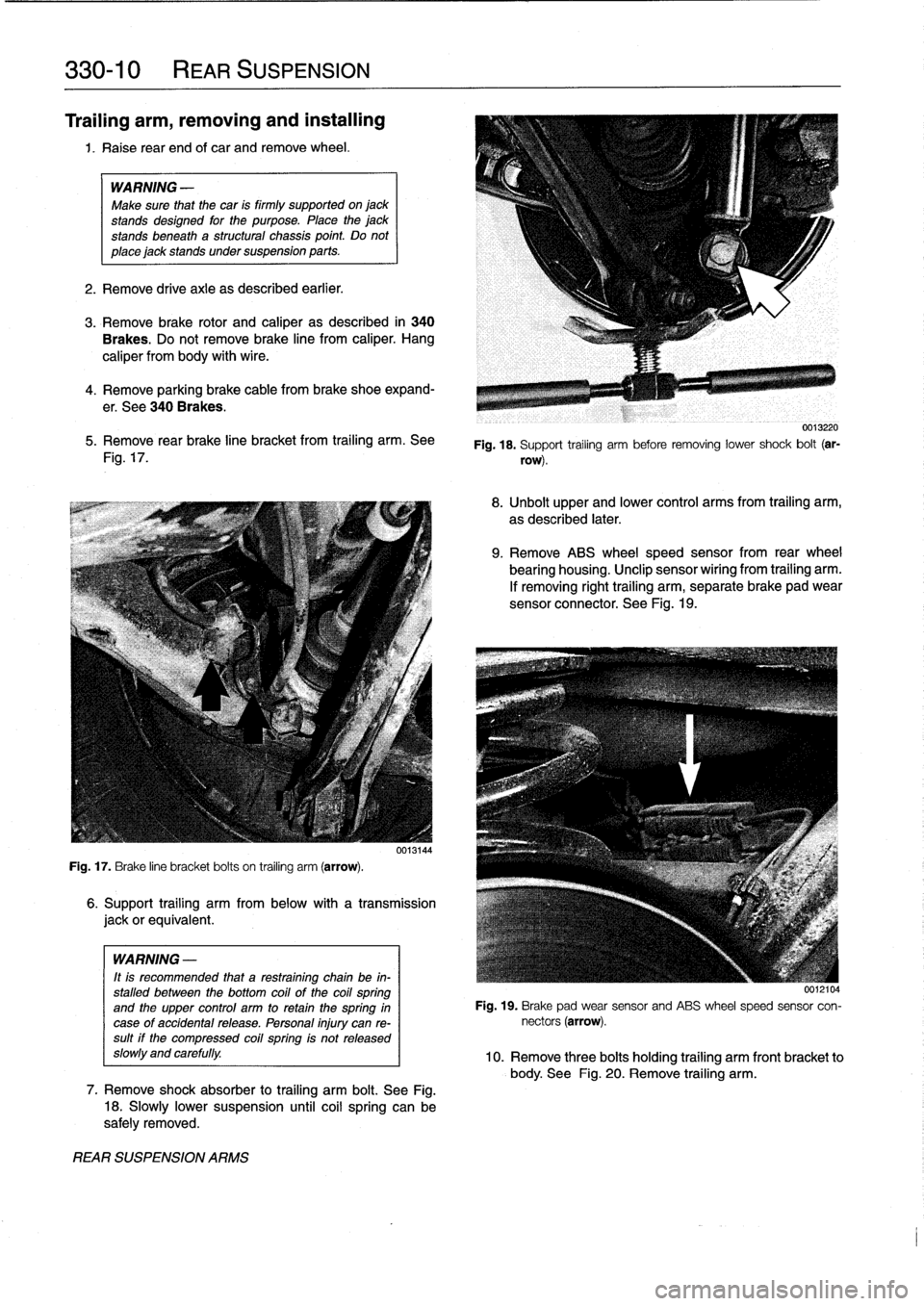
330-
1
0
REAR
SUSPENSION
Trailing
arm,
removing
and
installing
1
.
Raise
rear
end
of
car
and
remove
wheel
.
WARNING
-
Make
sure
that
the
car
is
firmly
supported
on
jack
standsdesigned
for
the
purpose
.
Place
the
jack
standsbeneatha
structural
chassis
point
.
Do
not
place
jack
stands
under
suspension
parts
.
2
.
Remove
drive
axle
as
described
earlier
.
3
.
Remove
brake
rotor
and
caliper
as
described
in
340
Brakes
.
Do
not
remove
brake
line
from
caliper
.
Hang
caliper
from
body
with
wire
.
4
.
Remove
parking
brakecable
frombrake
shoe
expand-
er
.
See
340
Brakes
.
5
.
Remove
rear
brake
line
bracket
from
trailing
arm
.
See
Fig
.
17
.
Fig
.
17
.
Brake
line
bracket
bolts
on
trailing
arm
(arrow)
.
WARNING
-
It
is
recommended
that
a
restraining
chain
be
in-
stalled
between
the
bottom
coil
of
the
coil
spring
and
the
upper
control
arm
to
retainthe
spring
in
case
of
accidentalrelease
.
Personal
injury
can
re-sult
if
the
compressed
coil
spring
is
not
released
slow1y
and
carefully
.
REAR
SUSPENSION
ARMS
6
.
Support
trailing
arm
from
below
with
a
transmission
jackorequivalent
.
7
.
Remove
shock
absorber
to
trailing
arm
bolt
.
See
Fig
.
18
.
Slowly
lower
suspension
until
coil
spring
can
be
safely
removed
.
0013220
Fig
.
18
.
Support
trailing
arm
before
removing
lower
shock
bolt
(ar-
row)
.
8
.
Unbolt
upper
and
lower
control
arms
from
trailing
arm,
as
described
later
.
9
.
Remove
ABS
wheel
speed
sensor
from
rear
wheel
bearing
housing
.
Unclip
sensor
wiríng
from
trailing
arm
.
If
removing
right
trailing
arm,
separate
brake
pad
wear
sensor
connector
.
See
Fig
.
19
.
0012104
Fig
.
19
.
Brake
pad
wear
sensor
and
ABS
wheel
speed
sensor
con-
nectors
(arrow)
.
10
.
Remove
three
bolts
holding
trailing
arm
front
bracket
to
body
.
See
Fig
.
20
.
Remove
trailing
arm
.
Page 291 of 759
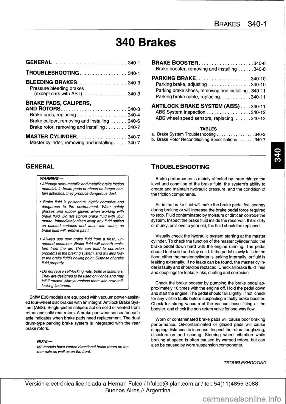
Brake
rotor,
removing
and
installing
.
.
.
.
.
.
.
.
340-7
MASTER
CYLINDER
............
.
.
.
.
.
.
.340-7
Master
cylinder,
removing
and
installing
.
...
.
340-7
GENERAL
TROUBLESHOOTING
WARNING
-
"
Although
semi-metallic
and
metallic
Brake
friction
materials
in
Brake
pads
or
shoes
no
longer
con-
tain
asbestos,
they
produce
dangerous
dust
.
"
Brake
fluid
is
poisonous,
highly
corrosive
and
dangerous
to
the
environment
Wear
safety
glasses
and
rubber
gloves
when
working
with
Brake
fluid
.
Do
not
siphonBrake
fluid
with
your
mouth
.
Immediately
clean
away
any
fluid
spilled
on
painted
surfaces
and
wash
with
water,
asBrake
fluid
will
remove
paint
.
"
Always
use
new
Brake
fluid
froma
fresh,
un-
opened
container
.
Brake
fluid
will
absorb
mois-
ture
from
the
air
.
This
canlead
to
corrosion
problems
in
the
brakingsystem,
and
will
also
low-
er
the
Brake
fluid's
boiling
point
.
Dispose
of
Brake
fluid
properly
.
"
Do
notreuse
self-locking
nuts,bolts
or
fasteners
.
They
are
designed
to
be
used
only
once
and
may
failif
reused
.
Always
replace
them
with
new
self-
locking
fasteners
.
BMW
E36
models
areequipped
with
vacuum
power-assist-
ed
four-wheel
disc
brakes
with
an
integral
Antilock
Brake
Sys-
tem
(ABS)
.
Single-pistoncalipers
act
on
solid
or
vented
front
rotors
and
solid
rear
rotors
.
A
brake
pad
wear
sensor
for
each
axle
indicates
when
brake
padsneed
replacement
.
The
dual
drum-type
parking
brakesystem
is
integrated
with
the
rear
brake
rotors
.
NOTE-
M3
models
havevented
directional
Brake
rotors
on
the
rearaxle
as
well
ason
the
front
.
340
Brakes
BRAKES
340-1
GENERAL
.
.
.
.
.
.
.........
.
.
.
..........
340-1
BRAKE
BOOSTER
.........
.
.
.
.
.
...
.
.
.
.
340-8
TROUBLESHOOTING
.......
.
......
.
...
340-1
Brake
booster,
removing
and
installing
....
.
.
340-8
PARKING
BRAKE
.
.....
.
...
.
.
.
.....
.
.
.
340-10
BLEEDING
BRAKES
.
.
.
.
.
.
.
.
..........
340-3
Parking
brake,adjusting
.
.
.
.
.
.
.
.
.
.
.....
.
340-10
Pressure
bleeding
brakes
Parking
brake
shoes,
removing
and
installing
.
340-11(except
cars
with
AST)
.
.
.
.
.
.
.
.
.
...
.
.
.
.
.340-3
Parking
Brake
cable,
replacing
.
.
.
.
.
.
.
.
.
.
.
.
340-11
BRAKE
PADS,
CALIPERS,
ANTILOCK
BRAKE
SYSTEM
(ABS)
.
.
.
.340-11
AND
ROTORS
..........
.
.......
.
.
.
.
.
.
.
340-3
ABS
System
Inspection
.
...
.
.......
.
.
.
..
340-12
Brake
pads,
replacing
............
.
.
.
.
.
.
.
340-4
ABS
wheel
speed
sensors,
replacing
.
.
.
.
..
340-12
Brake
caliper,
removing
and
installing
.
..
..
.
340-6
TABLES
a
.
Brake
System
Troubleshooting
.....
...
.
.
.....
.340-2
b
.
Brake
Rotor
Reconditioning
Specifications
.
.....
.340-7
Brakeperformance
is
mainly
affected
by
three
things
:
the
leve¡
and
condition
of
the
brake
fluid,
the
system's
abilíty
to
create
and
maintain
hydraulic
pressure,
and
the
condition
of
the
friction
components
.
Air
in
the
Brake
fluid
will
make
the
Brake
pedal
feel
spongy
during
braking
or
will
increase
the
Brake
pedalforce
required
to
stop
.
Fluid
contaminated
by
moisture
or
dirt
can
corrode
the
system
.
Inspect
the
Brake
fluid
inside
the
reservoir
.
Ifit
is
dirty
or
murky,
or
is
over
a
year
old,
the
fluid
should
be
replaced
.
Visually
check
the
hydraulic
system
startingat
the
master
cylinder
.
To
check
the
function
of
the
master
cylinder
hold
the
brake
pedal
down
hard
with
the
engine
running
.
The
pedal
should
feelsolid
and
stay
solid
.
If
the
pedal
slowly
falls
to
the
floor,
either
the
master
cylinder
is
leaking
internally,
or
fluid
is
leaking
externally
.
If
no
leaks
canbe
found,
the
master
cylin-
der
is
faulty
and
should
be
replaced
.
Check
all
Brake
fluid
lines
and
couplings
for
leaks,
kinks,
chafing
and
corrosion
.
Check
the
Brake
booster
by
pumping
the
Brake
pedal
ap-
proximately
10
times
with
the
engine
off
.
Hold
the
pedal
down
and
start
the
engine
.
The
pedal
should
fa¡¡
slightly
.
If
not,
check
for
any
visiblefaults
before
suspecting
a
faulty
brake
booster
.
Check
for
strong
vacuum
at
the
vacuum
hose
fitting
at
the
booster,
and
check
the
non-retum
valve
for
one-way
flow
.
Worn
or
contaminated
brake
pads
will
cause
poor
braking
performance
.
Oil-contaminated
or
glazed
pads
will
cause
stopping
distances
to
increase
.
Inspect
the
rotors
for
glazing,
discoloration
and
scoring
.
Steering
wheel
vibration
while
braking
at
speed
is
often
caused
by
warped
rotors,
but
can
also
be
caused
byworn
suspension
components
.
TROUBLESHOOTING