fault code BMW M3 1995 E36 User Guide
[x] Cancel search | Manufacturer: BMW, Model Year: 1995, Model line: M3, Model: BMW M3 1995 E36Pages: 759
Page 76 of 759
113-10
CYLINDER
HEAD
REMOVAL
AND
INSTALLATION
Tightening
Torques
"
Coolant
drain
plug
to
cylinder
block
.
.
25
Nm
(18
ft-1b)
"
Intake
manifold
support
to
manifold
.
.
15
Nm
(11
ft-Ib)
"
Lower
intake
manifold
to
cylinder
head
.
..........
.
..
...
15
Nm
(11
ft-Ib)
"
Lower
intake
manifold
to
upper
manifold
..........
.
..
...
15
Nm
(11
ft-Ib)
"
Radiator
cooling
fan
to
coolant
pump
.
40
Nm
(30
ft-Ib)
"
Radiator
drain
screw
to
radiator
...
.
2
.5
Nm
(22
in-lb)
CYLINDER
HEAD,
6-CYLINDER
For
ease
of
use
this
procedure
is
broken
into
subsections,
as
follows
:
General
Coolingsystem,
draining
Cyiinder
head
cover,
removing
Intake
manifold,
removing
Timing
chains,
uncoupling
Cylinder
head
assembly,
removing
WARNING
-
Allow
the
engine
to
cool
before
beginning
this
pro-
cedure
.
General
1
.
Working
inside
luggage
compartment,
disconnect
neg-
ative
(-)
battery
cable
.
CAUTION-
"
Prior
to
disconnectiog
the
battery,
read
the
bat-
tery
disconnection
cautions
given
at
the
front
of
this
manual
on
page
vi¡¡
.
"
Disconnecting
the
battery
may
erase
fault
code(s)
stored
in
control
module
memory
.
Check
for
fault
codes
using
special
BMW
diagnostic
equipment
2
.
Remove
front
exhaust
pipes
from
manifolds
.
Discard
nuts
.
3
.
Remove
air
filter
housing
complete
with
mass
air
flow
sensor
and
intake
air
ducting
.
Disconnect
vacuum
hos-
es
from
throttle
housing
.
4
.
On
M52
and
S52US
engines
:
Remove
secondary
air
injection
check-valve
from
front
of
engine
and
set
aside
.
CYLINDER
HEAD,
6-CYLINDER
Coolingsystem,
draining
5
.
Drain
engine
coolant
and
Rmove
coolant
hoses
from
thermostat
housing
.
Drain
engine
block
by
removing
block
drain
.
See
170
Radiator
and
Cooling
System
.
NOTE-
The
block
drain
is
on
the
exhaust
side
of
the
engine,
near
cylinder
no
.
5
.
6
.
Remove
radiator
cooling
fan
and
fan
shroud
.
See
170
Radiator
and
Cooling
System
.
NOTE-
The
radiator
cooling
fannut(32
mm
wrench)
has
left-
hand
threads
.
Cylinder
head,
removing
(6-cylinder
engine)
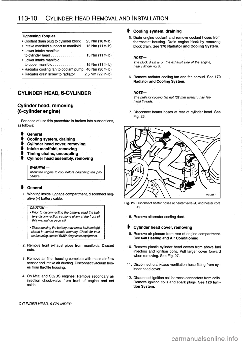
7
.
Disconnect
heater
hoses
at
rear
of
cylinder
head
.
See
Fig
.
26
.
'i
8
.
Remove
alternator
cooling
duct
.
Cylinder
head
cover,
removing
0012687
Fig
.
26
.
Disconnect
heater
hoses
at
heater
valve
(A)
and
heater
core
(B)
.
9
.
Remove
air
plenum
from
rear
of
engine
compartment
.
See640
Heating
and
Air
Conditioning
.
10
.
Remove
plastic
cylinder
head
covers
from
above
fuel
injectors
and
ignition
coils
.
Pull
larger
cover
forward
when
removing
.
See
Fig
.
27
.
11
.
Disconnect
crankcase
ventílation
hose
fitting
from
cyl-
inder
head
cover
.
12
.
Disconnect
ignition
coil
harness
connectors
from
coiis
.
Remove
ignition
coiis
and
spark
plugs
.
See
120
Igni-
tion
System
.
Page 97 of 759
GENERAL
......
.
.
.
.
.
.
.
.
.
...
.
.
.
.
.
.
.
.
.
.
117-1
Camshaft
timing
chains,
removing
(6-cylinder
engines)
....
.
....
..
....
..
...
.117-7
CAMSHAFT
TIMING
CHAIN,
Camshaft
timing
chains,
installing
4-CYLINDER
....
.
.
.
.
.
.
.
.
.
.
.
.......
.
...
117-2
6-clinderen
nes
117-11
Camshaft
timingchain,
removing
(
y
gi
(4-cylinder
engines)
...
..
....
..
...
...
....
117-2
VANOS
(VARIABLE
VALVE
TIMING)
.
..
117-14
Camshaft
timingchain,
installing
VANOS
system
operation,
testing
.....
.
....
117-14
(4-cylinder
engines)
...
..
...
....
..
.
.....
117-4
VANOS
control
unit,
removing
.
..
..........
117-16
CAMSHAFT
TIMINGCHAINS,
VANOS
control
unit,
installing
..
..
..........
117-17
6-CYLINDER
.
.........................
117-6
GENERAL
117
Camshaft
Timing
Chain
This
repair
group
covers
timing
chain
repair
information
for
the
4-
and
6-cylinder
engines
.
4-cylinder
enginesuse
one
double-row
chain
to
drive
the
dual
overhead
camshafts
.
See
Fig
.
1
.
Fig
.
1
.
M44
engine
valvetrain
chain
drive
.
M42
engine
is
similar
.
CAMSHAFT
TIMING
CHAIN
117-1
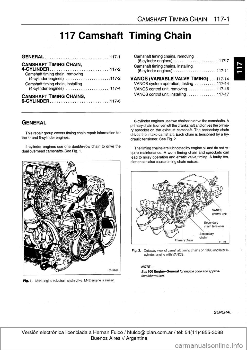
6-cylinder
enginesusetwo
chains
to
drive
the
camshafts
.
A
primary
chain
is
driven
off
the
crankshaft
and
drives
the
prima-
ry
sprocket
on
the
exhaustcamshaft
.
The
secondary
chain
drives
the
intake
camshaft
.
Each
chain
is
tensioned
by
a
hy-
draulic
tensioner
.
See
Fig
.
2
.
The
timing
chainsare
lubricated
by
engine
oil
and
do
not
re-`
quire
maintenance
.
A
worn
timing
chain
and
sprockets
can
lead
to
noisy
operation
and
erratic
valve
timing
.
A
faulty
ten-
sioner
can
also
cause
timing
chaín
noises
.
Primarychain
NOTE-
See
100
Engine-General
for
engine
code
and
applica-
tion
information
.
Secondary
chain
tensioner
Secondary
chain
B11115
Fig
.
2
.
Cutaway
view
of
camshaft
timing
chains
on1963
and
later
6-
cylinder
engine
with
VANOS
.
GENERAL
Page 103 of 759
Camshaft
timing
chains,
removing
(6-cylinder
engines)
1
.
Disconnect
negative
(-)
cable
from
battery
.
CA
UTION-
Disconnecting
the
battery
may
erase
fault
codes)
stored
in
control
module
memory
.
Check
for
fault
codes
using
special
BMW
diagnostic
equipment
.
2
.
Drain
engine
coolant
.
Drain
engine
block
by
removing
block
drain
.
Remove
radiator
cooling
fan
shroud
and
cooling
fan
.
See170
Radiator
and
Cooling
System
.
.
WARNING
-
Allow
the
engine
to
cool
before
openingor
draining
the
system
.
CAUTION-
Radiator
fan
has
left
hand
threads
.
NOTE-
The
block
drain
plug
is
located
on
the
exhaust
side
of
the
engine,
below
cylinder
no
.
4
.
3
.
Drain
engine
oíl
andremove
oil
pan
.
See
119
Lubrica-
tion
System
.
4
.
Remove
alternator
cooling
duct
.
5
.
Remove
two
large
coolant
hoses
from
thermostat
housing
.
Remove
engine
lifting
bracket
and
thermostat
housing
from
front
of
cylinder
head
.
6
.
Loosen
bolts
for
coolant
pump
pulley
.
Then
remove
drive
belts
for
alternator
andA/C
compressor
.
See
020
Maintenance
Program
.
Remove
coolant
pump
pulley
.
Fig
.
16
.
NOTE-
OnM50
engines
with
a
two-roller
drive
belt
tensioner,
remove
the
upper
rollerto
access
thetensioner
mount-
ing
bolts
.
NOTE-
Make
note
of
the
arrangement
of
the
rubber
insulators
when
removing
the
cylinder
head
cover
mounting
bolts
.
CAMSHAFT
TIMING
CHAIN
117-
7
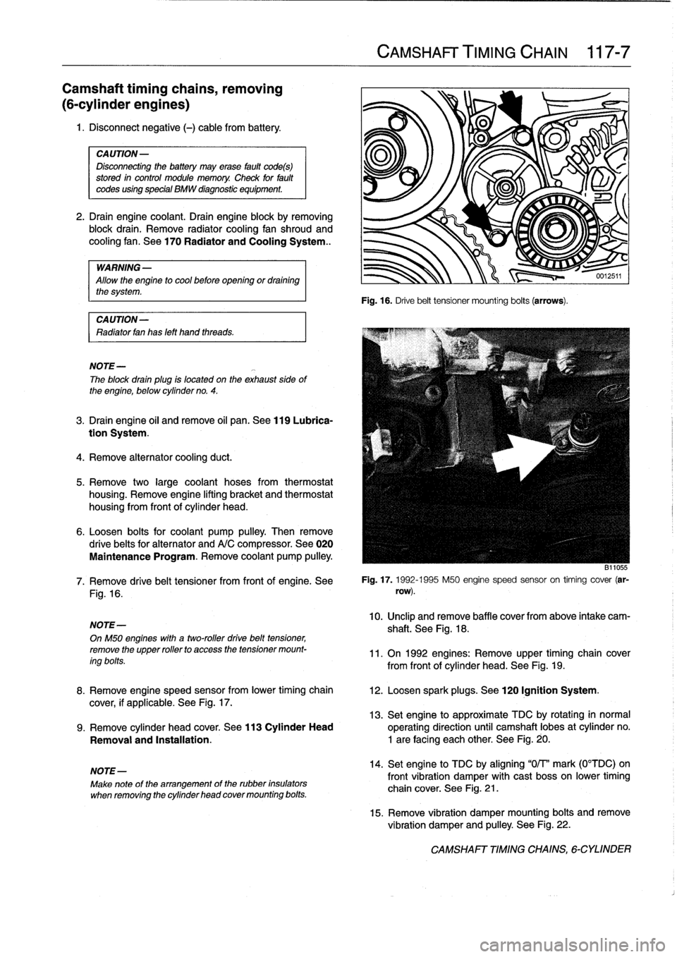
Fig
.
16
.
Drive
belt
tensioner
mounting
bolts
(arrows)
.
B11055
7
.
Remove
drive
belt
tensioner
from
front
of
engine
.
See
Fig
.
17
.
1992-1995
M50
engine
speed
sensor
on
timing
cover
(ar-
row)
.
10
.
Unclip
andremove
baffle
cover
from
above
intake
cam-
shaft
.
See
Fig
.
18
.
11
.
On
1992
engines
:
Remove
upper
timing
chain
cover
from
front
of
cylinder
head
.
See
Fig
.
19
.
8
.
Remove
engine
speed
sensor
from
lower
timing
chain
12
.
Loosen
spark
plugs
.
See
120
Ignition
System
.
cover,
if
applicable
.
See
Fig
.
17
.
13
.
Set
engine
to
approximate
TDC
by
rotating
in
normal
9
.
Remove
cylinder
head
cover
.
See
113
Cylinder
Head
operating
direction
until
camshaft
lobes
at
cylinder
no
.
Removal
and
Installatíon
.
1
are
facing
each
other
.
See
Fig
.
20
.
14
.
Set
engine
to
TDC
by
aligning
"0/T'
mark
(0°TDC)on
front
vibration
damper
with
cast
bosson
lower
timing
chain
cover
.
See
Fig
.
21
.
15
.
Remove
vibration
damper
mounting
bolts
and
remove
vibration
damper
and
pulley
.
See
Fig
.
22
.
CAMSHAFT
TIMING
CHAINS,
6-CYLINDER
Page 111 of 759
Fig
.
36
.
BMW
special
tool
no
.
11
2
300
installed
through
bellhousing
and
finto
flywheel
.
8
.
Remove
oil
line
fitting
from
VANOS
control
unit
.
NOTE-
Wrap
the
VANOS
oil
line
fitting
with
a
shop
to
absorb
leaking
oil
.
9
.
Using
hollow
bolt
and
seals
from
oil
supply
line,
instan
BMW
special
tool
no
.
11
3
450
(air
line
fitting)
and
con-
nect
a
supply
of
compressed
air
(30-115
psi)
to
VANOS
oil
fitting
.
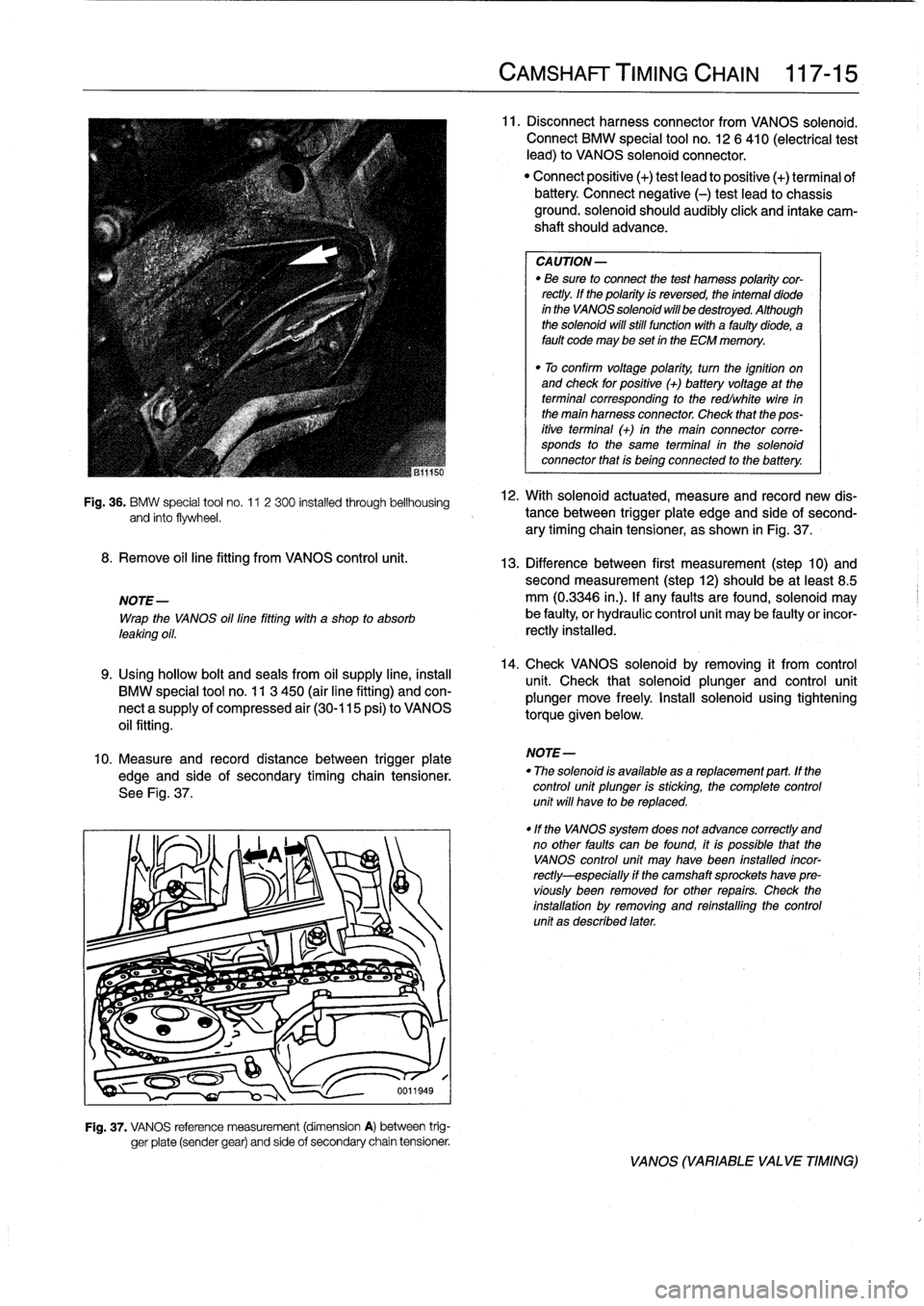
10
.
Measure
and
record
distance
between
trigger
plate
edge
and
side
of
secondary
timing
chain
tensioner
.
See
Fig
.
37
.
Fig
.
37
.
VANOS
reference
measurement
(dimension
A)
between
trig-
ger
píate
(sender
gear)
and
side
of
secondary
chain
tensioner
.
CAMSHAFT
TIMING
CHAIN
117-
1
5
11
.
Disconnectharness
connector
from
VANOS
solenoid
.
Connect
BMW
special
tool
no
.
12
6
410
(electrical
test
lead)
to
VANOS
solenoid
connector
.
"
Connect
positive
(+)
test
lead
to
positive
(+)
terminal
ofbattery
Connect
negative
(-)
test
leadto
chassis
ground
.
solenoid
should
audibly
click
and
intake
cam-
shaft
should
advance
.
CA
UTION-
"
Be
sure
to
connect
the
test
hamess
polaritycor-
rectly
.
lf
the
polarity
is
reversed,
the
intemal
diode
in
the
VANOS
solenoid
will
be
destroyed
.
Although
the
solenoid
will
still
functionwith
a
faultydiode,
a
fault
code
may
be
set
in
the
ECM
memory
.
"
To
confirm
voltage
polarity,
turn
the
ignition
on
and
check
for
positive
(+)
batteryvoltage
at
the
terminal
corresponding
to
the
redlwhite
wire
in
the
main
harness
connector
.
Check
that
the
pos-
itive
terminal
(+)
in
the
main
connector
corre-
sponds
to
the
same
terminal
in
the
solenoid
connector
that
is
being
connected
to
the
battery
.
12
.
With
solenoid
actuated,
measure
and
record
new
dis-
tance
between
trigger
plate
edge
and
side'of
second-
ary
timing
chain
tensioner,
as
shown
in
Fig
.
37
.
13
.
Difference
between
first
measurement
(step
10)
andsecond
measurement
(step12)
should
be
at
least
8
.5
mm
(0
.3346
in
.)
.
lf
any
faults
arefound,
solenoid
may
be
faulty,
or
hydraulic
control
unit
may
be
faulty
or
incor-
rectly
installed
.
14
.
Check
VANOS
solenoid
byremoving
it
from
control
unit
.
Check
that
solenoid
plunger
and
control
unit
plunger
move
freely
.
Install
solenoid
using
tighteníng
torque
given
below
.
NOTE-
"
The
solenoid
is
available
asareplacement
part
.
lf
the
control
unit
plunger
is
sticking,
the
complete
control
unit
will
have
to
be
replaced
.
"lf
the
VANOS
system
does
not
advance
correctly
and
no
other
faults
can
be
found,
itis
possible
that
the
VANOS
control
unit
may
Nave
been
fnstalled
incor-
rectly-especially
if
the
camshaft
sprockets
have
pre-
víously
been
removed
for
other
repairs
.
Check
the
installation
by
removing
and
reinstalling
the
control
unit
as
described
later
.
VANOS
(VARIABLE
VALVE
TIMING)
Page 127 of 759
IGNITION
SYSTEM
DIAGNOSTICS
IGNITION
SYSTEM
SERVICE
Poor
driveability
may
have
a
variety
of
causes
.
The
fault
On
4-cylinder
engines,
an
ignition
coil
pack
is
mounted
to
may
lie
with
the
ignition
system,
the
fuel
system,
parts
of
the
the
passenger
side
strut
tower
in
the
engine
compartment
.
emission
control
system,
or
a
combination
of
the
three
.
Be-
The
coil
pack
integrates
4
individual
coils
.
cause
of
these
interrelated
functions
and
their
effects
oneach
other,
it
is
often
difficult
to
know
where
to
begin
looking
for
On
6-cylinder
engines,
an
ignition
coil
is
located
directly
problems
.
above
each
spark
plug
.
For
this
reason,
effective
troubleshooting
should
alwaysbe-
gin
with
an
interrogation
of
the
On-Board
Diagnostic
(OBD)
system
.
The
OBD
system
detects
certain
emissions-related
engine
management
malfunctions
.
When
faults
are
detected,
the
OBD
system
stores
a
Diagnostic
Trouble
Code
(DTC)
in
the
system
ECM
.
In
addition,
the
Check
Enginewarning
light
will
come
on
if
an
emissions-related
fault
is
detected
.
Two
generations
of
OBD
areusedon
the
cars
coveredby
this
manual
.
See
100
Engine-General
for
OBD
information
.
On-Board
Diagnostics
"
1992-1995
models
............
...
.
..
...
OBD
I
"
1996
and
later
models
.........
.......
..
OBD
II
NOTE-
"
On
carswith
OBD
ti,
specialized
OBD
11
scan
tool
equipment
mustbeused
to
access
DTCs,
either
using
the
BMW
special
tool
or
a
`generic"
OBD
11
scan
tool
.
"
The
OBD
11
fault
memory
(including
an
illuminated
Check
Engine
light)
can
only
be
reset
using
the
spe-
cial
scan
tool
.
Removing
the
connector
from
the
ECM
or
dísconnecting
the
battery
will
not
erase
the
fault
memory
.
Basic
Troubleshooting
Principies
An
engine
that
starts
and
runs
indicates
the
ignition
system
is
fundamentally
working-delivering
voltage
toat
least
some
of
the
sparkplugs
.
A
hard-starting
or
poor-running
engine,
however,
may
indicate
ignition
coil
problems,
cracked
or
dete-
riorated
spark
plug
wires
(4-cylinder
engines
only),
and
worn
or
fouled
spark
plugs
.
WARNING
-
Inefficient
combustion
(richair/fuel
mixture)
can
cause
the
catalytic
converter
to
overheat
and
plug
.
An
overheated
catalytic
converter
can
also
bea
tire
hazard
.
Checking
for
Spark
IGNITION
SYSTEM
120-
3
WARNING
-
If
a
spark
test
is
done
incorrectly,
damage
to
theen-
gine
control
module
(ECM)
or
the
ignitioncoil(s)
may
result
.
Checking
for
spark
is
difficult
onengines
with
distributorless
ignition
systems
.
Try
Rmovng
the
plugs
and
inspecting
for
differences
be-
tween
them
.
A
poor-firing
plug
may
be
wet
with
fuel
and/or
black
and
sooty,
butnot
always
.
If
a
coil
is
not
operating,
the
engine
management
system
will
electrically
disable
the
fuel
injectorto
that
cylinder
.
The
key
is
to
look
for
differences
be-
tween
cylinders
.
Ignition
coil,
testing
and
replacing
(4-cylinder
engine)
1.
Disconnect
mainharness
connector
from
coils
:
"
On
M42
engine,
remove
plastic
covering
from
coils
and
disconnect
individual
harness
connectors
.
"
On
M44
engine,
disconnect
main
harness
connectorat
end
of
coil
pack
.
See
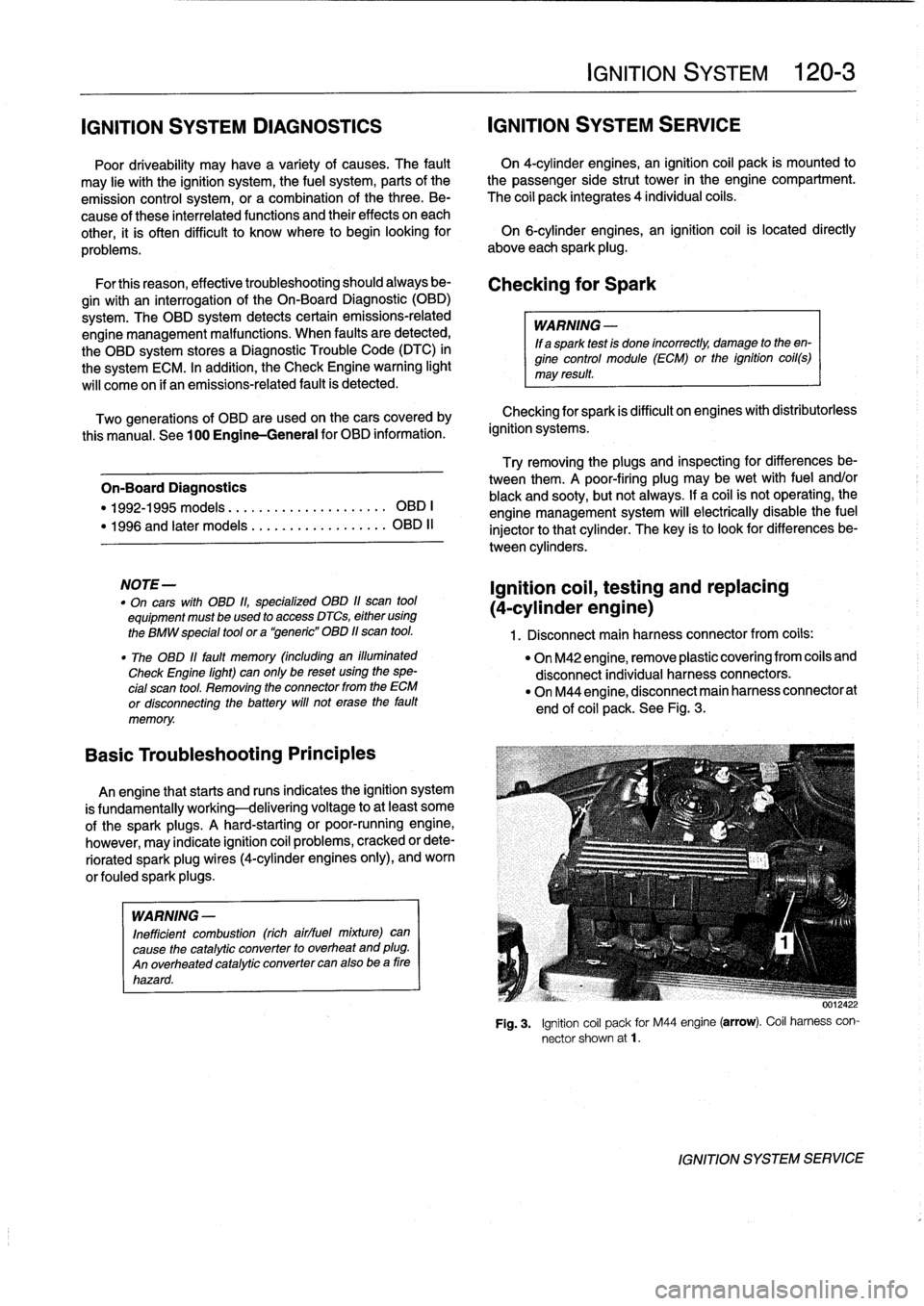
Fig
.
3
.
Fig
.
3
.
Ignition
coil
pack
for
M44
engine
(arrow)
.
Coil
harness
con-
nector
shown
at1
.
IGNITION
SYSTEM
SERVICE
Page 129 of 759
CAUTION
-
The
wiring
to
termina¡
15
(+)
of
the
coil(vía
the
ig-
nition
switch)
is
not
fuse
protected
.
Use
care
when
testíng
thiscircuit
.
4
.
Turn
ignition
off
.
5
.
Use
a
multimeter
to
test
coil
primary
resistanceat
coil
terminals
.
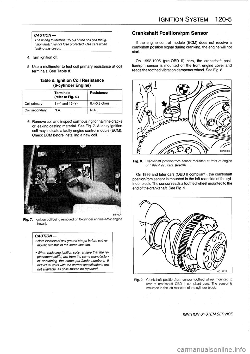
See
Table
d
.
Table
d
.
Ignition
Coil
Resistance
(6-cylinder
Engine)
Terminals
Resistance
(referto
Fig
.
4
.)
Coil
primary
1
1
(-)
and
15
(+)
X
0
.4-0
.8
ohms
Coil
secondary
l
N
.A
.
N
.A
.
6
.
Remove
coil
and
inspect
coil
housing
for
hairline
cracks
or
leaking
casting
material
.
See
Fig
.
7
.
A
leaky
ignition
coil
may
indícate
a
faulty
engine
control
module
(ECM)
.
Check
ECM
before
installing
a
new
coil
.
811004
Fig
.
7
.
Ignition
coil
being
removed
on
6-cylinder
engine
(M52
engine
shown)
.
CA
UTION-
"
Note
location
of
coil
ground
straps
before
coilre-
moval
;
reinstallin
the
same
location
.
"
When
replacing
ignition
coils,
ensure
that
the
re-
placement
coil(s)
are
from
the
same
manufactur-
er
containing
the
same
partlcode
numbers
.
If
individual
coils
with
the
correct
specifications
are
not
available,
all
coils
should
be
replaced
.
IGNITION
SYSTEM
120-
5
Crankshaft
Position/rpm
Sensor
If
the
engine
control
module
(ECM)
does
not
receive
a
crankshaft
position
signal
during
cranking,
the
engine
will
not
start
.
On
1992-1995(pre-OBD
II)
cars,
the
crankshaft
posi-
tion/rpm
sensor
is
mounted
on
the
front
engine
cover
and
reads
the
toothed
vibration
dampener
wheel
.
See
Fig
.
8
.
Fig
.
8
.
Crankshaft
position/rpm
sensor
mounted
at
front
of
engine
on
1992-1995
cars
.
(arrow)
.
On
1996
and
latee
cars
(OBD
II
compliant),
the
crankshaft
position/rpm
sensor
is
mounted
in
the
left
rear
side
of
the
cyl-
inderblock
.
The
sensor
reads
a
toothed
wheel
mounted
to
the
end
of
the
crankshaft
.
See
Fig
.
9
.
Fig
.
9
.
Crankshaft
position/rpm
sensor
toothed
wheel
mounted
to
rear
of
crankshaft
OBD
II
compliant
cars
.
The
sensor
is
mounted
in
the
left
rear
side
of
the
cylinder
block
.
IGNITION
SYSTEM
SERVICE
Page 131 of 759
Camshaft
position
(CMP)
sensor,
replacing
(6-cylinder
engine)
1
.
Remove
plastic
cover
from
above
fuel
injectors
.
2
.
Disconnect
harness
connector
from
VANOS
solenoid
and
unscrew
solenoid
from
VANOS
control
unit
.
Re-
"
Clean
contactsurface
on
engine
block
before
fnstall
move
oil
supply
line
from
VANOS
control
unit
.
See
117
ing
knock
sensors
.
Camshaft
Timing
Chain
.
3
.
Remove
camshaft
position
(CMP)
sensor
from
left
frontof
cylinder
head,
next
to
top
of
oil
filter
housing
.
"
Knock
sensor
to
cylinder
block
....
20
Nm
(15
ft
.
lbs
.)
4
.
Disconnect
CMP
sensor
harnessfrom
under
intake
manifold
.
5
.
Installation
is
reverse
of
removal
.
Use
a
new
O-ring
when
installing
sensor
.
Be
sure
wiring
is
rerouted
in
same
orientation
.
Tightening
Torques
"
CMP
sensor
to
cylinder
head
....
.
.
..
5
Nm
(3
.5
ft-Ib)
"
VANOS
oil
supply
pipe
to
VANOS
control
unit
...........
.
..
32
Nm
(24
ft-Ib)
"
VANOS
solenoid
to
VANOS
control
unit
...
.
.................
30
Nm
(22
ft-Ib)
Knock
sensors,
replacing
Knock
sensors
are
usedon
engines
with
Bosch
DME
M1
.7,
Bosch
DME
M3
.3
.1,
Bosch
DME
M5
.2,
and
Siemens
MS
41
.1
engine
management
systems
.
The
knocksensors
are
bolted
to
the
left
sideof
the
cylinder
block
and
monitor
the
combus-
tion
chamber
for
engine-damaging
knock
.
If
engine
knock
is
detected,
the
ignition
point
is
retarded
accordingly
via
the
en-
gine
control
module
.
CA
UTION-
"
Label
knock
sensorharness
connectors
before
disconnecting
them
.
The
connectors
must
not
be
interchanged
.
Engine
damage
may
result
if
the
sensors
are
monitoring
the
wrong
cytinders
.
"
Note
the
installed
angle
of
the
knock
sensoron
the
block
before
removing
it
.
Reinstall
the
sensor
in
the
same
position
.
Be
sure
to
usea
torque
wrench
when
tightening
the
sensormounting
bola
NOTE
-
"
On
M52
engines,
a
single
harness
connects
the
twosensors
to
the
main
harness
connector
.
The
shorter
cable
lead
fs
for
the
knock
sensor
for
cytinders
4,
5,
and
6
.
Tightening
Torque
IGNITION
SYSTEM
120-
7
0012730
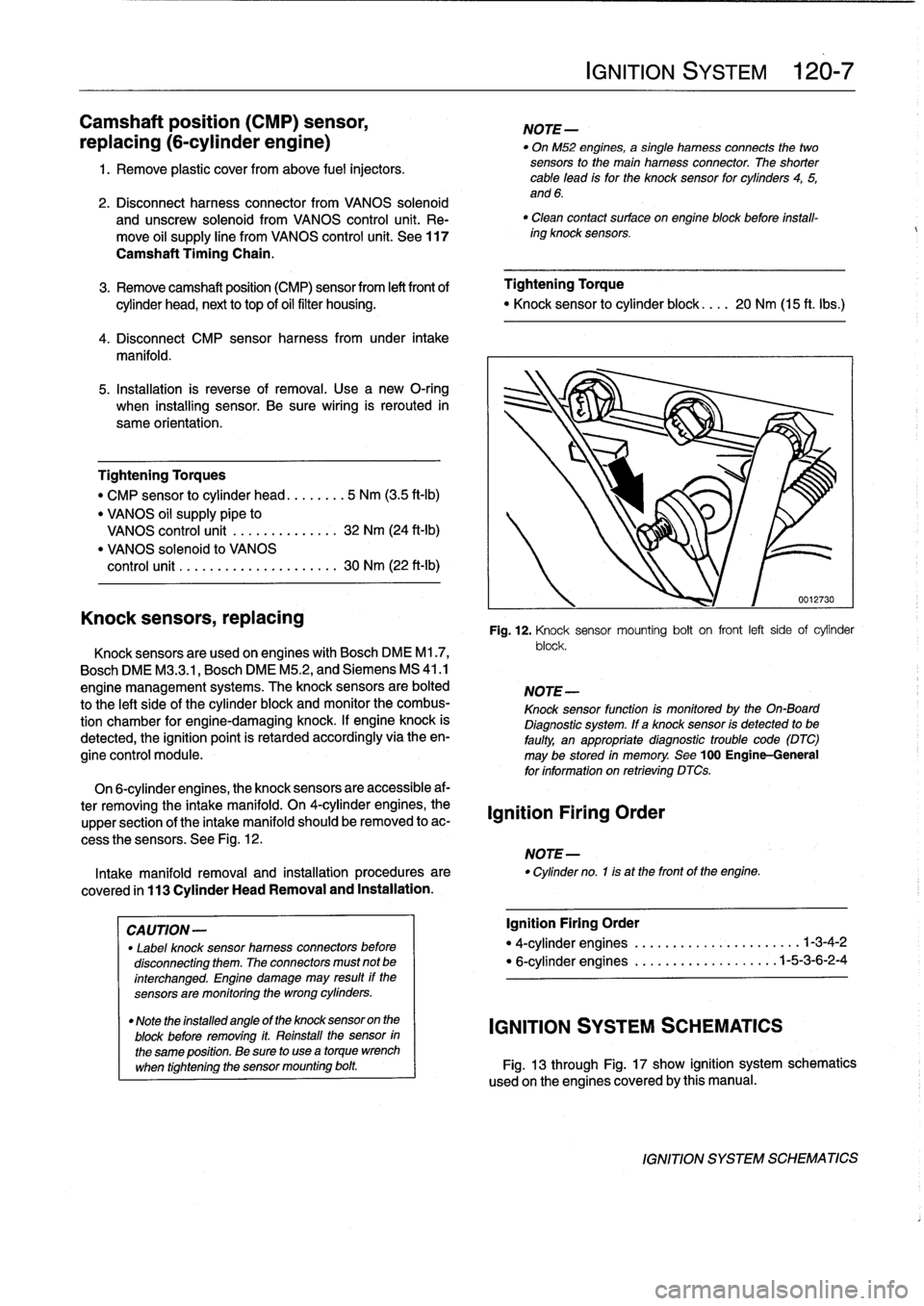
Fig
.
12
.
Knock
sensor
mounting
bolt
on
front
left
side
of
cylinder
block
.
NOTE-
Knock
sensor
function
Is
monitoredby
the
On-Board
Diagnostic
system
.
If
a
knock
sensor
is
detected
to
be
faulty,
an
appropriatediagnostic
trouble
code
(DTC)
may
be
stored
in
memory
.
See
100
Engine-General
for
information
on
retrieving
DTCs
.
On
6-cylinder
engines,
the
knock
sensors
are
accessible
af-
ter
removing
the
intake
manifold
.
On
4-cylinder
engines,
the
upper
section
of
the
intake
manifold
should
be
removed
to
ac-
cess
the
sensors
.
See
Fig
.
12
.
NOTE-
Intakemanifold
removal
and
installation
procedures
are
"
Cylinder
no
.
1is
at
the
front
of
the
engine
.
covered
in
113
Cylinder
HeadRemoval
and
Installation
.
Ignition
Firing
Order
Ignition
Firing
Order
"
4-cylinder
engines
.....
..
...
.
..........
.1-3-4-2
"
6-cylinder
engines
...........
..
.
.
..
..
1-5-3-6-2-4
IGNITION
SYSTEM
SCHEMATICS
Fig
.
13
through
Fig
.
17
show
ignition
system
schematics
usedon
the
enginescoveredby
this
manual
.
IGNITION
SYSTEM
SCHEMATICS
Page 137 of 759
CHARGING
SYSTEM
TROUBLESHOOTING
.............
.
.
.
.
.121-2
Charging
System
Quick-Check
...
.
..
.
...
.
121-2
Static
current
draw,
checking
........
.
...
.
121-2
BATTERY
SERVICE
....................
121-3
Battery
Testing
.
.
.
.
.
.........
.
........
.
121-3
Hydrometer
Testing
.
...
.
.
.
...
.
.........
121-3
Battery
Open-Circuit
Voltage
Test
....
.
....
121-4
Battery
Load
Voltage
Test
.
.
.
.
.
.
.........
121-4
Battery
Charging
.
.
.
.
...
.
.
.
.
.
.
.
.........
121-4
ALTERNATOR
SERVICE
.
.
.
.
.
.
.....
.
...
121-4
Chargingsystem,checking
.
.
.
.
.
.........
121-4
Alternator,
removingand
installing
(4-cylinder
engine)
....
.
.
.
.
.
.
.
.........
121-5
Alternator,
removingand
installing
(6-cylinder
engine)
..
.
.
.
.
.
.
.
.
.
.........
121-6
GENERAL
The
charging
system
consists
of
a
belt-driven
alternator
with
integral
voltage
regulator
and
a
battery
mounted
in
the
luggage
compartment
.
Various
versions
of
alternators,
voltage
regulators,
starters,
and
batteries
are
used
in
the
E36
cars
.
It
is
important
to
re-
place
components
according
tothe
original
equipment
speci-
fication
.
Check
with
an
authorized
BMW
dealer
for
specific
application
and
parts
information
.
WARNING
-
"
Weargoggles,
rubbergloves,
and
a
rubberapron
when
working
around
batteries
and
battery
acid
(electrolyte)
.
"
Battery
acid
contains
sulfuric
acid
and
can
cause
skin
irritation
and
burning
.
ff
acid
is
spilled
onyour
skin
or
clothing,
flush
the
area
at
once
with
large
quantities
of
water
.
lf
electrolyte
gets
into
your
eyes,flush
them
with
largequantities
of
clean
wa-
terfor
several
minutes
and
call
a
physician
.
"
Batteries
that
are
being
charged
or
are
fully
charged
give
off
explosive
hydrogen
gas
.
Keep
sparks
and
open
flames
away
.
Do
not
smoke
.
BATTERY,
STARTER,
ALTERNATOR
121-1
121
Battery,
Starter,
Alternator
GENERAL
..
.
...
.
........
.
...
.
.
.
.
.
.
.
.
.
121-1
Voltage
regulator,
removing
and
ínstalling
.
.
.
121-6
Alternator
brushes,
inspecting
and
replacing
.121-7
STARTER
SERVICE
....
.
.
.
.
.
..........
.121-7
Starter
Troubleshootíng
121-7
15
..
.
.
.
.
.
........
.
.
.
Starter,
removing
and
installing
(4-cylinder
engine)
....
.
.
.
............
.
121-8
Starter,
removing
and
installing
(6-cylinder
engine
with
manual
transmission)
..
.
...........
.
...
121-8
Starter,
removing
and
installing
(6-cylinder
engine
with
automatic
transmission)
................
121-9
Solenoid
switch,
removingand
installing
....
121-10
TABLES
a
.
Battery,
Starter
and
Charging
System
Troubleshooting
............
.
.
.
.
:...
........
121-2
b
.
Specific
Gravity
of
Battery
Electrolyte
at
80°F
(27°C)
...............
.
.
..
..........
121-3
c
.
Open-Circuit
Voltage
and
Battery
Charge
........
121-4
d
.
Battery
Load
Test-Minimum
Voltage
.
..........
121-4
CAUTION
-
"
Prior
to
disconnectiog
the
battery,
read
the
bat-tery
disconnection
cautions
given
at
the
front
of
this
manual
on
page
viii
.
"
Disconnecting
the
battery
cables
may
erase
fault
codes
stored
in
control
unit
memory
.
"
Always
disconnect
the
negative
()
battery
cable
first
and
reconnect
it
last
.
Cover
the
battery
post
with
an
insulating
material
whenever
the
cable
is
removed
.
"
After
reconnecting
the
battery,
the
power
window
motors
must
be
reinitialized
.
See
511
Door
Win-
dows
.
"
Never
reverse
the
battery
cables
.
Even
a
momen-
tary
wrong
connection
can
damage
the
alternatoror
other
electrical
components
.
"
Battery
cables
may
be
the
same
color
.
Label
ca-blebefore
removing
.
GENERAL
Page 150 of 759
130-
4
FUEL
INJECTION
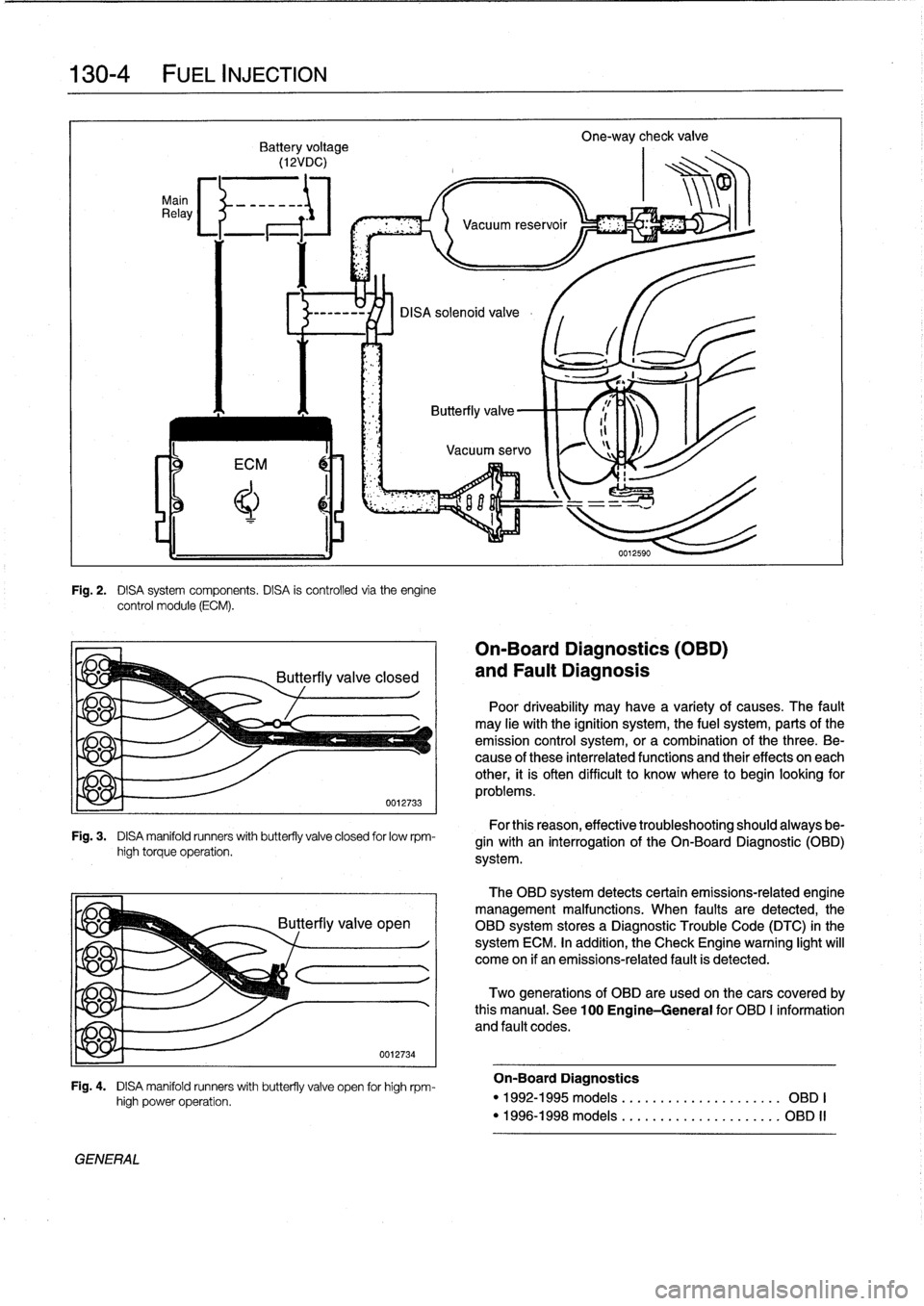
Main
Relay
Fig
.
2
.
DISA
system
components
.
DISA
is
controlled
via
theengine
control
module
(ECM)
.
Fig
.
3
.
DISA
manifold
runners
with
butterfly
valve
closed
for
lowrpm-
high
torque
operation
.
yje
q
GENERAL
high
power
operation
.
0012734
Fig
.
4
.
DISA
manifold
runners
with
butterfly
valve
open
for
high
rpm-
On-Board
Diagnostics
(OBD)
and
Fault
Diagnosis
Poor
driveability
may
have
a
variety
of
causes
.
The
fault
may
He
withthe
ignition
system,
the
fuel
system,
parts
ofthe
emission
control
system,
ora
combination
of
thethree
.
Be-
cause
of
these
interrelated
functions
and
their
effects
on
each
other,
it
is
often
difficult
to
know
where
to
begin
looking
for
problems
.
For
this
reason,
effective
troubleshooting
should
always
be-
gin
with
an
interrogation
of
the
On-Board
Diagnostic
(01313)
system
.
The
OBD
system
detects
certain
emissions-related
engine
management
malfunctions
.
When
faults
are
detected,the
OBD
system
storesa
Diagnostic
Trouble
Code
(DTC)
in
the
system
ECM
.
In
addition,
the
Check
Engine
warning
light
will
come
on
if
an
emissions-related
fault
is
detected
.
Two
generations
of
OBD
are
used
on
thecars
covered
by
this
manual
.
See
100
Engine-General
for
OBD
I
information
and
fault
codes
.
On-Board
Diagnostics
"
1992-1995models
....
.
...
...
.
...
......
OBD
I
"
1996-1998models
....
.
..
.
.
.
..
...
......
OBD
II
Page 152 of 759
130-
6
FUEL
INJECTION
Warnings
and
Cautions
For
personal
safety,
as
well
as
the
protection
of
sensitive
electronic
components,
the
following
warnings
and
cautions
should
be
adhered
to
when
working
on
the
engine
manage-
ment
system
.
GENERAL
WARNING
-
"
The
ignition
system
produces
high
voltages
that
can
be
fatal
.
Avoid
contact
with
exposed
termi-
nals
.
Use
extreme
caution
when
working
onacar
with
the
ignition
switched
on
or
the
engine
run-
ning
.
"
Do
not
touch
or
disconnect
any
high
voltage
ca-
bles
from
the
coils
or
spark
plugs
while
the
engine
is
running
or
beingcranked
by
the
starter
.
"
Connect
and
disconnect
the
DME
system
wiring
and
test
equipment
leads
only
when
the
ignition
is
switched
off
.
"
Gasoline
is
highly
flammable
and
fts
vaporsare
explosive
.
Do
not
smoke
or
work
on
a
car
near
heaters
or
other
fire
hazards
when
diagnosing
and
repalring
fuel
system
problems
.
Have
a
tire
extinguisher
avaílable
in
case
of
an
emergency
.
"
When
working
onan
open
fuel
system,
wear
suit-
able
hand
protection,
asprolonged
contact
wfth
fuel
can
cause
illnesses
and
skin
disorders
.
"
Renew
fuel
system
hoses,
clamps
and
O-rings
any
timethey
are
removed
.
"
Before
makingany
electrical
tests
that
require
the
engine
to
be
cranked
using
the
starter,
disable
the
ignition
system
as
described
in
120
Ignition
System
.
CAUTION-
"
Prior
to
disconnecting
the
battery,
read
the
bat-
tery
disconnectinn
cautions
given
at
the
front
of
this
manual
onpage
vifi
.
"
Do
not
connect
any
test
equipment
that
delivers
a
12-volt
power
supply
to
terminal
15
(+)
of
the
ig-
nitioncoil
.
The
current
flow
may
damage
the
ECM
.
In
general,
connect
test
equipment
only
as
speclfied
by
BMW,
this
manual,
or
the
equipment
maker
.
"
Only
use
a
digital
multlmeter
for
electrical
test
.
"
Only
use
an
LED
test
light
for
quick
tests
.
"
Disconnecting
the
battery
may
erase
fault
code(s)
stored
in
memory
.
Check
for
fault
codes
prior
to
disconnecting
the
battery
cables
.
ff
the
Check
Engine
light
ís
illuminated,
see100En-
gine-General
for
DME
fault
code
information
.
ff
any
other
system
faults
have
been
detected
(indi-
catedbyan
illuminated
warning
light),
see
an
au-
thorized
BMW
dealer
.
Additional
systems
with
self-diagnostic
capabilities
include,
ABS
(Anti-
lock
brakes),
SRS
(Airbags),
EML
and
ASC+T
and
AST
(Traction
Control)
.
"
Do
not
run
the
engine
wfth
any
of
the
spark
plug
wires
dlsconnected
.
Catalytic
converter
damage
may
result
.
"
Always
waitat
least
40
seconds
afterturning
off
the
ignition
before
removing
the
engine
control
module
(ECM)
connector
.
ff
the
connector
isre-
moved
before
this
time,
residual
power
in
the
sys-
tem
relay
may
damage
the
control
module
.
"
Cleanliness
is
essential
when
working
onan
open
fuel
system
.
Thoroughly
clean
fuel
line
con-
nections
and
surroundlng
areas
before
loosen-
ing
.
Avoid
moving
the
car
.
Only
fnstall
cleanparts
.
"
Fuel
system
cleaners
and
other
chemical
addi-
tives
other
than
those
specifically
recommended
by
BMW
may
damage
the
catalytic
converter,
the
oxygensensor
or
other
fuel
supply
components
.