Remove starter BMW M3 1995 E36 Owner's Manual
[x] Cancel search | Manufacturer: BMW, Model Year: 1995, Model line: M3, Model: BMW M3 1995 E36Pages: 759
Page 146 of 759

121-1
O
BATTERY,
STARTER,
ALTERNATOR
9
.
Remove
starter
from
above
.
10
.
Check
starter
pinion
gear
and
flywheel
teeth
for
dam-
age
.
11
.
Installation
is
reverse
of
removal
.
Tightening
Torques
"
tntakemanifold
to
cylinder
head
M7
nut
...
.
................
...
.
15
Nm
(11
ft-Ib)
M8
nut/bolt
.............
.
.
..
...
22
Nm
(16
ft-Ib)
"
Starter
to
engine
block
(M10
bolt)
...
50
Nm
(37
ft-Ib)
"
Support
bracket
to
starter
(M5
nut)
...
5
Nm
(44
in-lb)
"
Support
bracket
to
engine
block
(M10
bolt)
.
.
..
..
...
47
Nm
(35
ft-Ib)
"
Wire
toterminal
50
(M6
nut)
.
..
.....
6
Nm
(53
in-lb)
"
Wire
toterminal
30
(M8
nut)
...
.....
12
Nm
(9
ft-Ib)
Solenoid
switch,
removing
and
installing
1
.
Remove
starter
as
described
above
.
Tightening
Torque
2
.
Remove
cover
from
solenoid
switch
.
"
Field
winding
strap
to
starter
(M8)
...
.
12
Nm
(9
ft-Ib)
3
.
Disconnect
fieid
winding
strap
between
starter
motor
and
solenoid
switch
.
NOTE-
The
condition
of
the
field
winding
strap
is
critical
.
If
it
is
damaged,
bumed
or
partially
melted
through,
a
new
or
rebuilt
starter
motor
is
needed
.
4
.
Remove
solenoidswitch
mounting
screws,
and
sepa-
,
rate
solenoid
from
starter
.
See
Fig
.
12
.
CAUTION-
When
installing
fieid
winding
strap
to
starter,
posi-
tion
it
so
that
it
does
not
contact
the
starter
body
.
STARTER
SERVICE
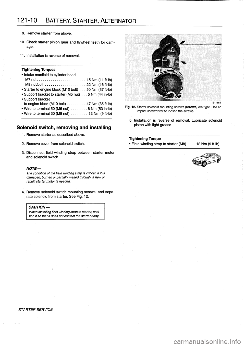
131~184
Fig
.
12
.
Starter
solenoid
mounting
screws
(arrows)
are
tight
.
Use
en
impact
screwdriver
to
loosen
the
screws
.
5
.
Installation
is
reverse
of
removal
.
Lubricate
solenoid
pistos
with
light
grease
.
Page 152 of 759

130-
6
FUEL
INJECTION
Warnings
and
Cautions
For
personal
safety,
as
well
as
the
protection
of
sensitive
electronic
components,
the
following
warnings
and
cautions
should
be
adhered
to
when
working
on
the
engine
manage-
ment
system
.
GENERAL
WARNING
-
"
The
ignition
system
produces
high
voltages
that
can
be
fatal
.
Avoid
contact
with
exposed
termi-
nals
.
Use
extreme
caution
when
working
onacar
with
the
ignition
switched
on
or
the
engine
run-
ning
.
"
Do
not
touch
or
disconnect
any
high
voltage
ca-
bles
from
the
coils
or
spark
plugs
while
the
engine
is
running
or
beingcranked
by
the
starter
.
"
Connect
and
disconnect
the
DME
system
wiring
and
test
equipment
leads
only
when
the
ignition
is
switched
off
.
"
Gasoline
is
highly
flammable
and
fts
vaporsare
explosive
.
Do
not
smoke
or
work
on
a
car
near
heaters
or
other
fire
hazards
when
diagnosing
and
repalring
fuel
system
problems
.
Have
a
tire
extinguisher
avaílable
in
case
of
an
emergency
.
"
When
working
onan
open
fuel
system,
wear
suit-
able
hand
protection,
asprolonged
contact
wfth
fuel
can
cause
illnesses
and
skin
disorders
.
"
Renew
fuel
system
hoses,
clamps
and
O-rings
any
timethey
are
removed
.
"
Before
makingany
electrical
tests
that
require
the
engine
to
be
cranked
using
the
starter,
disable
the
ignition
system
as
described
in
120
Ignition
System
.
CAUTION-
"
Prior
to
disconnecting
the
battery,
read
the
bat-
tery
disconnectinn
cautions
given
at
the
front
of
this
manual
onpage
vifi
.
"
Do
not
connect
any
test
equipment
that
delivers
a
12-volt
power
supply
to
terminal
15
(+)
of
the
ig-
nitioncoil
.
The
current
flow
may
damage
the
ECM
.
In
general,
connect
test
equipment
only
as
speclfied
by
BMW,
this
manual,
or
the
equipment
maker
.
"
Only
use
a
digital
multlmeter
for
electrical
test
.
"
Only
use
an
LED
test
light
for
quick
tests
.
"
Disconnecting
the
battery
may
erase
fault
code(s)
stored
in
memory
.
Check
for
fault
codes
prior
to
disconnecting
the
battery
cables
.
ff
the
Check
Engine
light
ís
illuminated,
see100En-
gine-General
for
DME
fault
code
information
.
ff
any
other
system
faults
have
been
detected
(indi-
catedbyan
illuminated
warning
light),
see
an
au-
thorized
BMW
dealer
.
Additional
systems
with
self-diagnostic
capabilities
include,
ABS
(Anti-
lock
brakes),
SRS
(Airbags),
EML
and
ASC+T
and
AST
(Traction
Control)
.
"
Do
not
run
the
engine
wfth
any
of
the
spark
plug
wires
dlsconnected
.
Catalytic
converter
damage
may
result
.
"
Always
waitat
least
40
seconds
afterturning
off
the
ignition
before
removing
the
engine
control
module
(ECM)
connector
.
ff
the
connector
isre-
moved
before
this
time,
residual
power
in
the
sys-
tem
relay
may
damage
the
control
module
.
"
Cleanliness
is
essential
when
working
onan
open
fuel
system
.
Thoroughly
clean
fuel
line
con-
nections
and
surroundlng
areas
before
loosen-
ing
.
Avoid
moving
the
car
.
Only
fnstall
cleanparts
.
"
Fuel
system
cleaners
and
other
chemical
addi-
tives
other
than
those
specifically
recommended
by
BMW
may
damage
the
catalytic
converter,
the
oxygensensor
or
other
fuel
supply
components
.
Page 157 of 759

3
.
Observe
fuel
pressure
gauge
after
20
minutes
.
The
pressure
shouldnot
drop
off
more
than
0
.5
bar
from
system
pressure
listed
in
Tablec
.
4
.
When
finished
testing,
disconnect
pressure
gauge
and
reconnect
fuel
line
.
If
the
fuel
system
does
not
maintain
pressure,
check
visual-
¡y
for
leaks
in
fuel
lines
orat
unions
.
Leaks
can
also
be
due
to
a
leaking
injector
or
a
faulty
fuel
pump
check
valve
.
Check
the
pump
check
valve
by
repeating
the
test,
butbefore
turning
the
fuel
pump
off,
pinch
off
theretum
line
at
the
fuel
rail
.
If
the
pressure
is
now
maintained,
the
fault
is
most
likely
the
fuel
pump
check
valva
.
Tabla
c
.
Fuel
Pressure
Specifications
Engine
1
Fuel
pressure
4-cytinder
1
3
.0
t
0
.2
bar
(43
.5
t
2
.9psi)
6-cytinder
M50/S50US
engine
3
.0
t
0
.2
bar
(43
.5
±2
.9psi)
M52/S52US
engine
3
.5
f
0
.2
bar
(51
t
2.9psi)
Fuel
pressure
regulator
response
to
engine
load,
testing
1
.
With
fuel
pressure
gauge
connected,
reinstallfuel
pump
relay
.
Start
engine
and
allow
it
to
idle
.
NOTE-
The
fuel
pressure
should
be
lower
by0
.4-0.7
bar
from
the
specifications
listed
in
Table
c
.
Engine
vacuum
act-
ing
on
the
fuel
pressure
regulator
diaphragm
reduces
the
fuel
pressure
.
2
.
With
engine
idling,
remove
vacuum
hose
from
regula-
tor
.
Pressure
should
increase
.
3
.
Reconnecthose
and
check
that
pressure
decreases
.
4
.
When
finished
testing,
disconnect
pressure
gauge
and
reconnect
fuelline
.
Tighten
hose
clamp
.
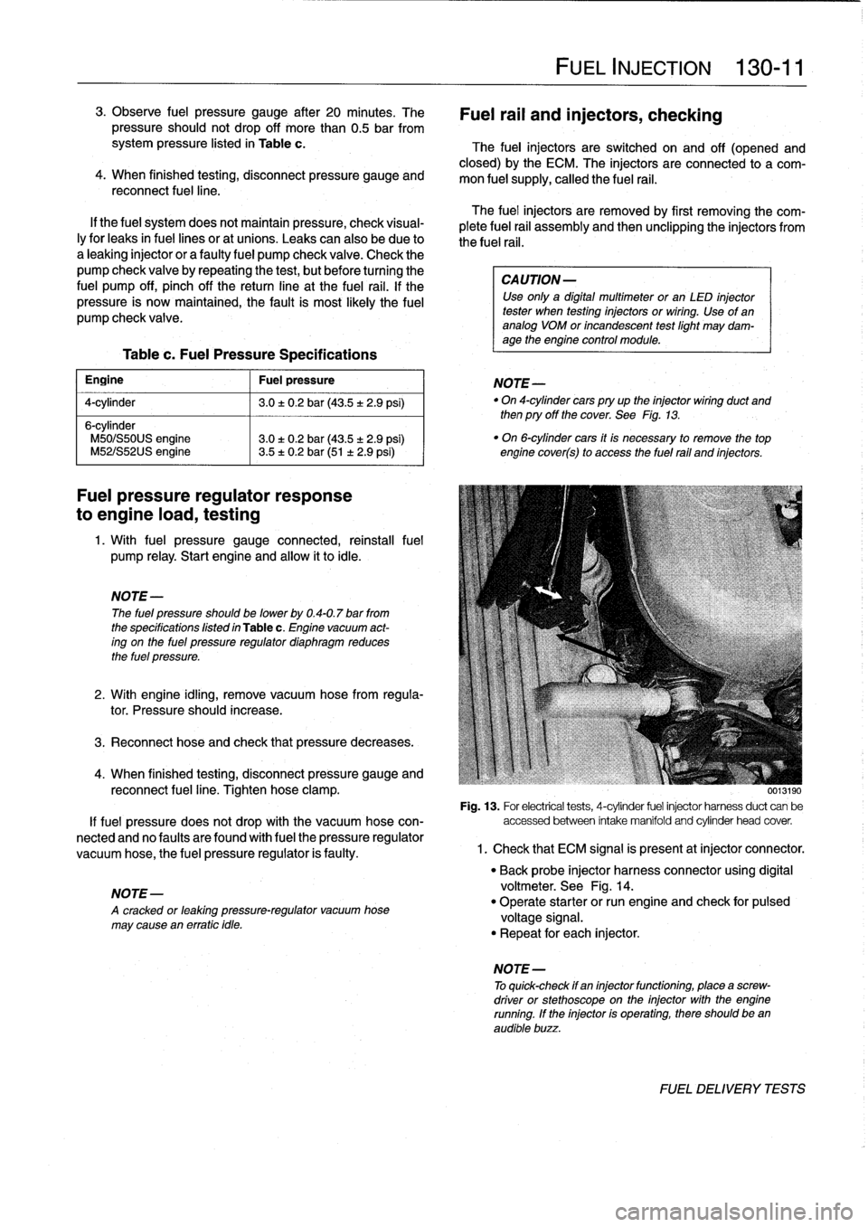
0013190
Fig
.
13
.
For
electrical
tests,
4-cytinder
fuel
injector
harnessduct
can
be
If
fuel
pressure
does
not
drop
with
the
vacuum
hose
con-
accessed
between
intake
manifold
and
cytinder
head
cover
.
nected
and
no
faulty
are
found
with
fuel
the
pressure
regulator
vacuum
hose,
the
fuel
pressure
regulator
is
faulty
.
1
.
Check
that
ECM
signal
is
present
atinjector
connector
.
NOTE-
A
cracked
or
leaktng
pressure-regulator
vacuum
hose
may
cause
en
erratic
tdle
.
FUEL
INJECTION
130-
11
Fuel
rail
and
injectors,
checking
The
fuel
injectors
are
switched
on
and
off
(opened
and
closed)
by
the
ECM
.
The
injectors
are
connected
to
a
com-
mon
fuel
supply,
callad
the
fuel
rail
.
The
fuel
injectors
are
removed
by
first
removing
the
com-
plete
fuel
rail
assembly
and
then
unclipping
the
injectors
from
the
fuel
rail
.
CA
UTION-
Use
only
a
digital
multimeter
or
an
LED
injector
tester
when
testing
injectors
or
wiring
.
Use
of
ananalog
VOM
or
incandescent
testlight
may
dam-
age
the
engine
control
module
.
NOTE-
"
On
4-cytindercars
pry
up
the
injector
wiring
duct
and
then
pry
off
the
cover
.
See
Fig
.
13
.
"
On
6-cytinder
cars
it
is
necessary
to
remove
the
top
engine
cover(s)
to
access
the
fuel
rail
and
injectors
.
"
Back
probe
injector
harness
connector
using
digital
voltmeter
.
See
Fig
.
14
.
"
Operate
starter
or
run
engine
and
check
for
pulsad
voltage
signal
.
"
Repeat
for
each
injector
.
NOTE
-
To
quick-check
if
en
injectorfunctioning,
place
a
screw-
driver
or
stethoscope
on
the
injector
with
the
engine
running
.
If
the
injector
is
operating,there
should
been
audible
buzz
.
FUEL
DELIVERYTESTS
Page 389 of 759

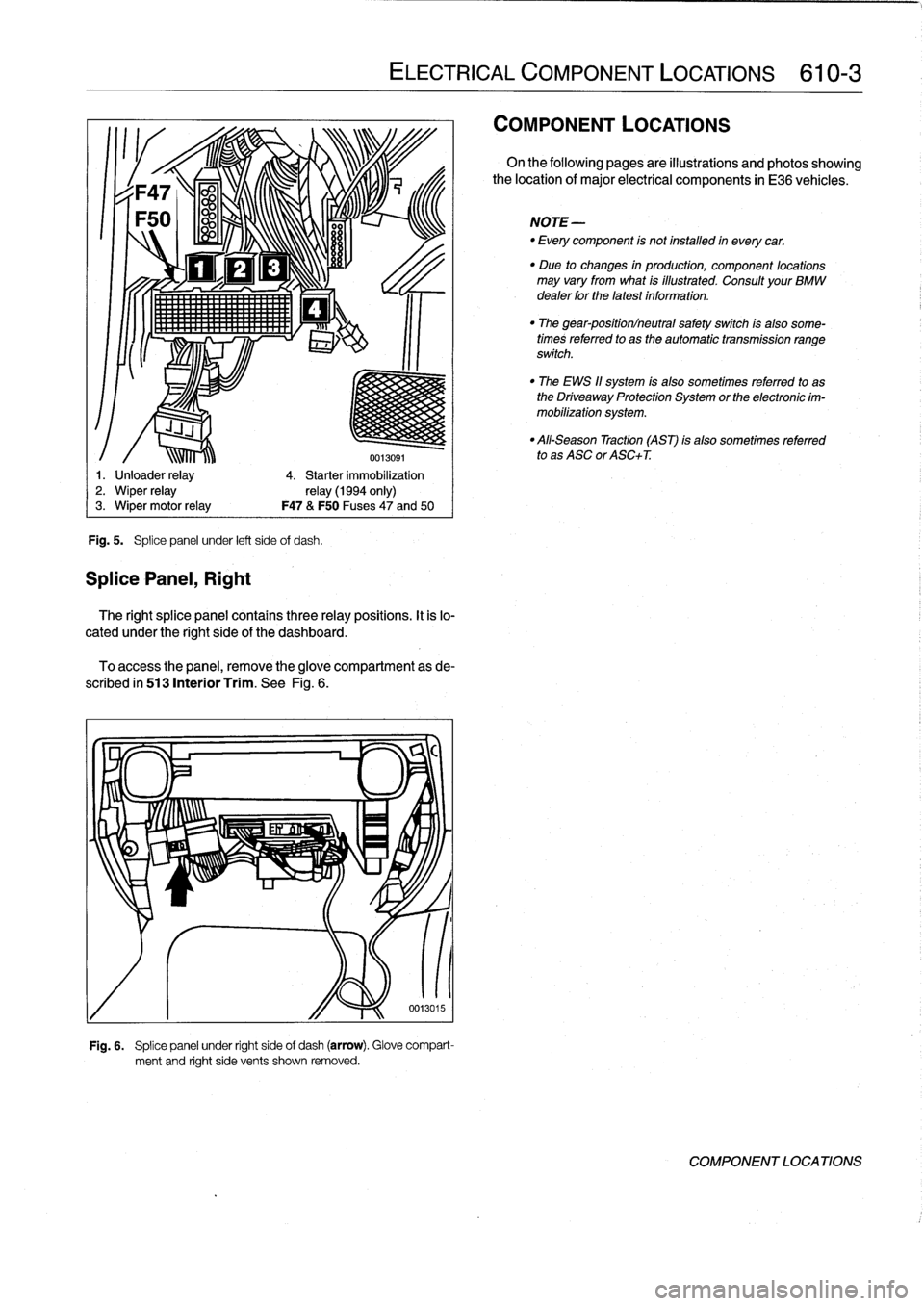
Fig
.
5
.
Splice
panel
under
left
side
of
dash
.
SplicePanel,
Right
ir1!
1,
111lí~lll
.
'
ELECTRICAL
COMPONENT
LOCATIONS
610-3
0013091
1
.
Unloader
relay
4
.
Starter
immobilization
2
.
Wiper
relay
relay
(1994
only)
3
.
Wiper
motor
relay
F47
&
F50
Fuses47
and
50
The
right
splice
panel
contains
three
relay
positions
.
It
is
lo-
cated
under
the
right
side
of
the
dashboard
.
To
access
the
panel,
remove
theglove
compartment
as
de-
scribed
in
513
Interior
Trim
.
See
Fig
.
6
.
Fig
.
6
.
Splice
panel
under
right
side
of
dash
(arrow)
.
Glove
compart-
ment
and
right
side
vents
shown
removed
.
COMPONENT
LOCATIONS
On
the
following
pages
are
illustrations
and
photos
showing
the
location
of
major
electrical
components
in
E36
vehicles
.
NOTE-
-
Every
component
is
not
installed
in
everycar
.
"
Due
to
changes
in
production,
component
locations
may
vary
from
what
is
illustrated
.
Consult
your
BMW
dealer
for
the
latest
information
.
"
The
gear-position/neutral
safety
switch
ís
also
some-
times
referred
to
as
the
automatic
transmission
range
switch
.
"
The
EWS
11
system
is
also
sometimes
referred
to
as
the
Driveaway
Protection
System
or
the
electronic
im-
mobilization
system
.
"
All-Season
Traction
(AST)
is
also
sometimes
referred
to
as
ASC
or
ASC+T
.
COMPONENT
LOCATIONS