auxiliary fuse BMW M3 1998 E36 Workshop Manual
[x] Cancel search | Manufacturer: BMW, Model Year: 1998, Model line: M3, Model: BMW M3 1998 E36Pages: 759
Page 199 of 759
NOTE-
Some
cars
covered
by
this
manual
may
have
an
alter-
nate
cooling
fan
switchwith
switching
temperatures
of
176%190W
(80%88°C)
.
When
replacing
the
switch
check
theswitching
specifications,
whichshouldbe
stamped
on
the
switch
body
.
1
.
If
coolant
is
circulating
at
normal
operating
tempera-
ture,
but
auxiliary
cooling
fan
does
not
run,
disconnect
connector
from
radiator
temperature
switch
and
make
tests
listed
in
Table
c
.
Table
c
.
Auxiliary
Cooling
Fan
Temperature
Switch
Tests
Wires
jumpered
Test
Test
resuits
conditions
Black/green
(terminal2)
and
Ignition
ON
Fan
runs
on
brown
(terminal
1)
low
speed
Black/gray
(terminal
3)
and
Ignition
ON
Fan
runson
brown
(terminal
I
1)
high
speed
2
.
If
fan
runs
only
when
powered
directly
by
jumpered
connector
and
hot
coolant
is
circulating
through
radia-
tor,
radiator
temperature
switch
is
most
likelyfaulty
.
Use
a
new
sealing
ring
when
replacing
switch
Tightening
Torque
"
Temperature
switch
to
radiator
......
15
Nm
(11
ft-Ib)
3
.
If
auxiliary
fan
does
notrun
when
powered
directly,
check
for
battery
voltage
at
temperature
switch
connec-
tor
(black/green
wire)
with
ignition
on
.
If
battery
voltage
is
not
present,
check
fuses
.
See
610
Electrical
Com-
ponent
Locations
.
RADIATOR
AND
COOLING
SYSTEM
170-
5
~r~nmm
a
00
0
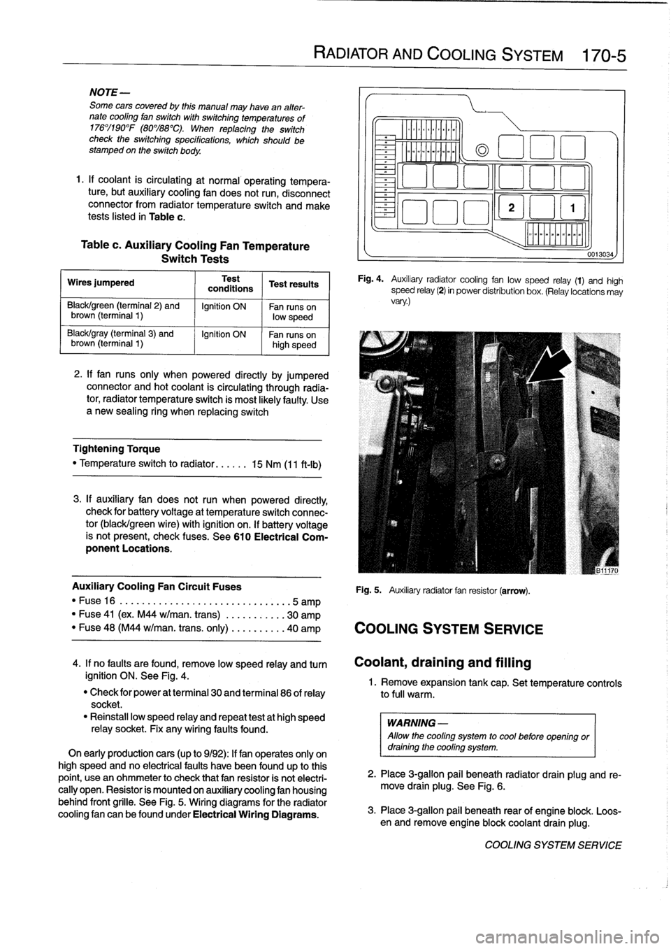
Fig
.
4
.
Auxiliary
radiator
cooling
fan
low
speed
relay
(1)
and
high
speed
relay
(2)
in
power
distribution
box
.
(Relay
locations
may
vary
.)
Auxiliary
Cooling
Fan
Circuit
Fuses
Fig
.
5
.
Auxiliary
radiator
fan
resistor
(arrow)
.
"
Fuse16
.
...................
..
..
...
...
.5
amp
"
Fuse
41
(ex
.
M44
w/man
.
trans)
.
..
.
..
.....
30
amp
"
Fuse
48
(M44
w/man
.
trans
.
only)
..
.
..
.....
40
amp
COOLING
SYSTEM
SERVICE
0013034
4
.
If
no
faults
are
found,
remove
low
speed
relay
and
turn
Coolant,draining
and
filling
ignition
ON
.
See
Fig
.
4
.
1
.
Remove
expansion
tank
cap
.
Set
temperature
controls
"
Check
for
power
at
terminal
30
and
terminal
86
of
relay
to
full
warm
.
socket
.
"
Reinstall
low
speed
relay
and
repeat
testat
high
speed
WARNING
-
relay
socket
.
Fix
any
wiring
faults
found
.
Allow
the
cooling
system
to
cool
before
openlng
or
On
early
productioncars
(up
to
9/92)
:
If
fan
operates
only
on
draining
the
cooling
system
.
high
speed
and
no
electrical
faults
have
been
foundup
to
this
point,
usean
ohmmeter
to
check
that
fan
resistor
is
not
electri-
2
.
Place
3
ra
allo
ug
.
beneath
radiator
drain
plug
and
re-
cally
open
.
Resistor
is
mounted
on
auxiliary
cooling
fan
housing
move
drain
plg
.
See
Fig
.
6
.
behind
front
grille
.
See
Fig
.
5
.
Wiring
diagrams
for
the
radiator
cooling
fan
canbefoundunder
Electrical
Wiring
Diagrams
.
3
.
Place
3-g
pail
beneath
rear
of
engine
blo
.
Loos-
en
and
re
mlon
ove
engine
blockcoolant
drain
plug
k
.
COOLING
SYSTEM
SERVICE
Page 387 of 759
610
Electrical
Component
Locations
GENERAL
...........
.
.
.
.
.
.
.
.
.
........
610-1
FOSE
POSITION
TABLES
..
.
.
.
.
.
.....
.
610-19
FUSE
AND
RELAY
POSITIONS
.
...
.
.
.
.
.
610-1
Fuse
Positions
.
.
.
................
.
.
.
.
.
610-1
Relay
Positions
.
.
.
.....
.
.
.
........
.
.
.
.
.
610-2
Auxiliary
RelayPanel
.....
.
...
.
........
.
610-2
SplicePanel,
Left
.
.
.
...
.
.
.
...
.
........
.
610-2
SplicePanel,
Right
.
.
.
.
.
.
.
.
...
.
.........
610-3
COMPONENT
LOCATIONS
.
.
.
.
.......
.
.610-3
Component
Location
Table
.
.
.
.
.
.
.........
610-9
GENERAL
FUSE
AND
RELAY
POSITIONS
This
repair
group
covers
f
use,
relay,
and
control
module
lo-
The
front
power
distribution
box,
an
auxiliary
relay
panel,cation
information
.
Electrical
equipment
and
accessories
in-
and
two
auxiliary
splice
panels
contain
most
of
the
fuses
and
stalled
varies
depending
on
model
and
model
year
.
Always
relays
in
E36
vehicles
.
Refer
to
the
component
location
later
confirm
that
the
proper
electrical
component
has
been
identi-
in
this
section,
as
well
as
the
tables
at
the
end
of
this
repair
fied
by
using
the
electrical
wiring
diagrams
.
group
for
electrical
component
location
.
WARNING
-
On
cars
equipped
with
airbags,
special
precautionsapply
to
any
electrical
system
testing
orrepair
.
Air-
bag
units
areexplosive
devices
and
mustbe
han-
dled
with
extremecare
.
Before
starting
any
work
onan
airbag
equipped
car,
refer
to
the
wamings
and
cautions
in
721
Airbag
System
(SRS)
.
CAUTION
-
"
Prior
to
disconnectiog
the
battery,
read
the
bat-
tery
disconnection
cautions
given
at
the
front
of
this
manual
on
page
viii
.
"
Relay
and
fuse
positions
are
subject
to
changeand
may
varyfrom
car
to
car
.
If
questions
arise,
an
authorized
BMW
dealer
is
the
best
source
for
the
most
accurate
and
up-to-date
information
.
"
A
good
way
to
verify
a
relay
position
isto
com-
pare
the
wiring
colors
at
the
relay
socket
to
thecolors
indicated
on
the
wiring
diagrams
located
at
the
rear
of
this
manual
.
"
Always
switchthe
ignition
off
and
disconnect
the
negative
(-)
battery
cable
before
removing
any
electrical
components
.
"
Connect
and
disconnect
ignition
system
wires,
multiple
connectors,
and
ignition
test
equipment
leads
only
while
the
ignition
is
switched
off
.
"
Only
usea
digital
multimeter
for
electrical
tests
.
ELECTRICAL
COMPONENT
LOCATIONS
610-1
TABLES
a
.
E36Component
Locations
...........
.
.
..
...
610-10b
.
1992
E36
Fuse
Positions
..........
..
.
.
.....
610-20c
.
1993
E36
Fuse
Positions
..........
..
..
.
....
610-22d
.
1994
E36
Fuse
Positions
.........
...
.......
610-24e
.
1995
E36
Fuse
Positions
.........
...
.......
610-26
f
.
1996
E36
Fuse
Positions
.........
...
.......
610-28g
.
1997-1998
E36
Fuse
Positions
..
.
..
...
.......
610-30
Fuse
Positions
CAUTION
-
"
Replace
fuses
with
those
of
the
same
rating
.
In-
stalling
a
fuse
with
higher
rating
can
lead
to
cir-
cuit
failure
and
may
also
start
a
fire
.
"
Relay/fuse
positions
vary
by
model
and
equip-
ment
.
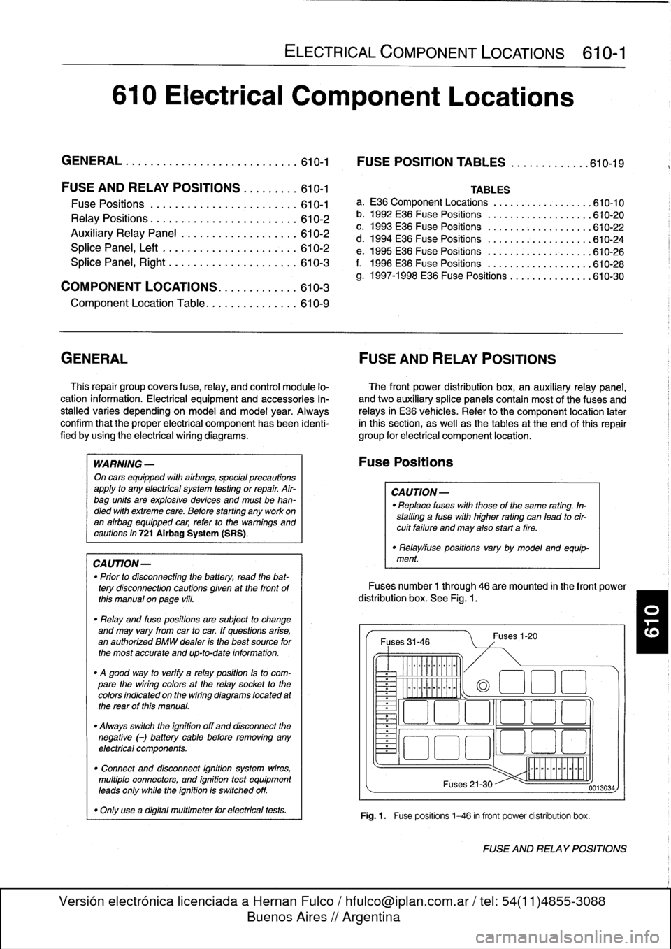
Fuses
number
1
through
46
are
mounted
in
the
front
power
distribution
box
.
See
Fig
.
1.
Fuses
31-46
~
Illlllllllll
°
-
Ilmmlmomlmoi
Fuses
1-20
(a
1
:1
E
El
~
~O!7
L~~n
4~
i
Fuses
21-30
Fig
.1.
Fuse
positions
1-46
in
front
power
distribution
box
.
0013034
FUSE
AND
RELAY
POSITIONS
Page 388 of 759
610-2
ELECTRICAL
COMPONENT
LOCATIONS
Fuses
number47
and
50are
mounted
on
the
left
side
splice
panel
.
Refer
lo
Fig
.
5
.
Fuse48
is
mounted
on
the
auxiliary
relay
panel
.
Refer
to
Fig
.
3
.
Fuse
49
is
mounted
in
the
right
side
of
the
luggage
compart-
ment
behind
the
trim
cover
.
Relay
Positions
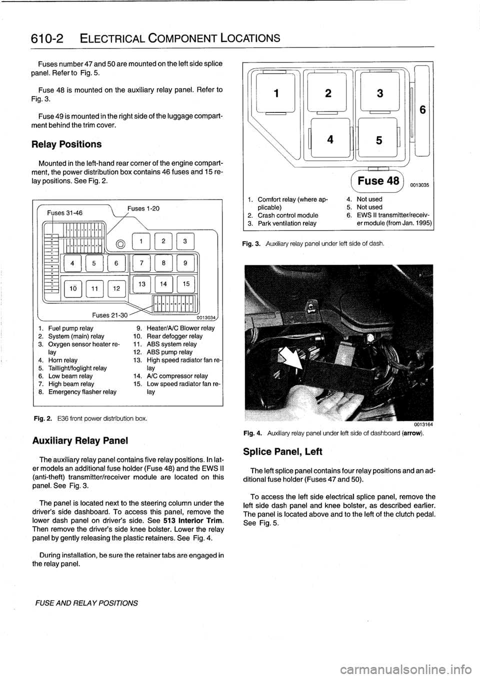
Mounted
in
the
left-hand
rear
comer
of
the
engine
compart-
ment,
the
power
distribution
box
contains
46
(uses
and
15
re-
lay
positions
.
See
Fig
.
2
.
Fuses31-46
-
Er
a
&QT
MM
~
Fig
.
2
.
E36
front
power
distribution
box
.
FUSE
AND
RELAY
POSITIONS
Fuses1-20
13
EL1
5
]
mmmmmmmmmm
Fuses
21-30
--
0013034)
1
.
Fuel
pump
relay
9
.
Heater/A/C
Blower
relay
2
.
System
(main)
relay
10
.
Rear
defogger
relay
3
.
Oxygen
sensorheater
re-
11
.
ABS
system
relay
lay
12
.
ABS
pump
relay
4
.
Horn
relay
13
.
High
speed
radiator
fan
re-
5
.
Taillight/foglight
relay
]ay
6
.
Low
beam
relay
14
.
A/C
compressor
relay
7
.
High
beam
relay
15
.
Low
speed
radiator
fan
re-
8
.
Emergency
flasherrelay
¡ay
Auxiliary
Relay
Panel
The
auxiliary
relay
panel
contains
five
relay
positions
.
In
lat-
er
modeis
an
additional
fuse
holder
(Fuse48)
and
the
EWS
II
(anti-theft)
transmitter/receiver
module
are
located
on
this
panel
.
See
Fig
.
3
.
The
panel
is
located
nextto
the
steering
column
under
the
driver's
side
dashboard
.
To
access
this
panel,
remove
the
pwer
dash
panel
on
driver's
side
.
See513
Interior
Trim
.
Then
remove
the
driver's
side
knee
bolster
.
Lower
the
relay
panel
by
gently
releasing
the
plastic
retainers
.
See
Fig
.
4
.
During
installation,
be
sure
the
retainer
tabs
are
engaged
in
the
relay
panel
.
Splice
Panel,
Left
3
¡ni
Fig
.
3
.
Auxiliary
relay
panel
under
left
side
of
dash
.
Fuse
48)
0013035
1
.
Comfort
relay
(where
ap-
4
.
Not
used
plicable)
5
.
Not
used
2
.
Crash
control
module
6
.
EWS
II
transmitter/receiv-
3
.
Park
ventilation
relay
er
module
(from
Jan
.
1995)
0013164
Fig
.
4
.
Auxiliary
relay
panel
under
left
sideof
dashboard
(arrow)
.
The
left
splice
panel
contains
four
relay
positions
and
an
ad-
ditional
fuse
holder
(Fuses
47
and
50)
.
To
access
the
left
side
electrical
splice
panel,
remove
the
left
side
dash
panel
and
knee
bolster,
as
described
earlier
.
The
panel
is
located
above
and
lo
the
left
of
the
clutch
pedal
.
See
Fig
.
5
.
Page 397 of 759
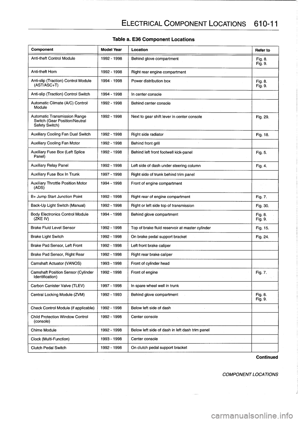
Table
a
.
E36
Component
Locations
Component
Model
Year
Location
Refer
to
Anti-theft
Control
Module
1992-1998
Behind
glove
compartment
Fig
.
8
.
Fig
.
9
.
Anti-theft
Horn
1
1992-1998
1
Right
rear
engine
compartment
Anti-slip
(Traction)
Control
Module
1994-1998
Power
distribution
box
Fig
.
8
.
(AST/ASC+T)
Fig
.
9
.
Anti-slip
(Traction)
Control
Switch
1994-1998
In
center
console
Automatic
Climate
(A/C)
Control
1992-1998
Behind
center
console
Module
AutomaticTransmission
Range
1992-1998
~
Next
to
gear
shift
lever
in
center
console
Fig
.
29
.
Switch
(Gear
Position/Neutral
Safety
Switch)
Auxiliary
Cooling
Fan
Dual
Switch
1992-1998
Right
side
radiator
1
Fig
.
18
.
Auxiliary
Cooling
Fan
Motor
1992-1998
Behind
front
grill
Auxiliary
Fuse
Box
(Left
Splice
1992-1998
I
Behind
left
front
footwell
kick-panel
Panel)
Auxiliary
RelayPanel
1
1992-1998
1
Left
side
of
dash
under
steering
column
Auxiliary
Fuse
Box
In
Trunk
1
1997-1998
1
Right
sideof
trunk
behind
trim
panel
AuADSry
ThrottlePosition
Motor
11994-1998
Front
of
engine
compartment
B+
Jump
Start
Junction
Point
1992-1998
Right
rear
of
engine
compartment
Fig
.
7
.
Back-Up
Light
Switch
(Manual)
1992-1998
Right
or
left
side
top
of
transmission
Fig
.
30
.
Body
Electronics
Control
Module
1994-1998
Behindglove
compartment
Fig
.
8
.
(ZKE
IV)
Fig
.
9
.
Brake
Fluid
Level
Sensor
1992-1998
Top
of
brake
fluid
reservoir
at
master
cylinder
Fig
.
15
.
Brake
Light
Switch
1
1992-1998
1
On
brake
pedal
supportbracket
Brake
Pad
Sensor,
Left
Front
1
1992-1998
1
Left
front
brake
caliper
Brake
Pad
Sensor,
Right
Rear
1992-1998
Right
rear
brake
caliper
Camshaft
Actuator
(VANOS)
1993-1998
Front
of
cylinder
head
Camshaft
Position
Sensor
(Cylinder
1992-1998
Front
of
engine
Identification)
Carbon
Canister
Valve
(TLEV)
1
1997-1998
1
In
sparewheel
well
in
trunk
ELECTRICAL
COMPONENT
LOCATIONS
610-11
Fig
.
5
.
Fig
.
4
.
Fig
.
24
.
Fig
.
7
.
Central
Locking
Module
(ZVM)
11992-1993
1
Behindglove
compartment
I
Fig
.
8
.
Fig
.
9
.
Check
Control
Module
(if
applicable)
1
1992
-
1998
1
Below
left
side
of
dash
Child
Protection
Window
Control
1992-1998
Center
console
(console)
Chime
Module
1992-1998
Below
left
side
of
dash
inleft
dash
trim
panel
Clock
(Multi-Function)
1993-1998
Center
console
Clutch
Pedal
Switch
1992-1998
On
clutch
pedal
support
bracket
Continued
COMPONENT
LOCATIONS
Page 399 of 759
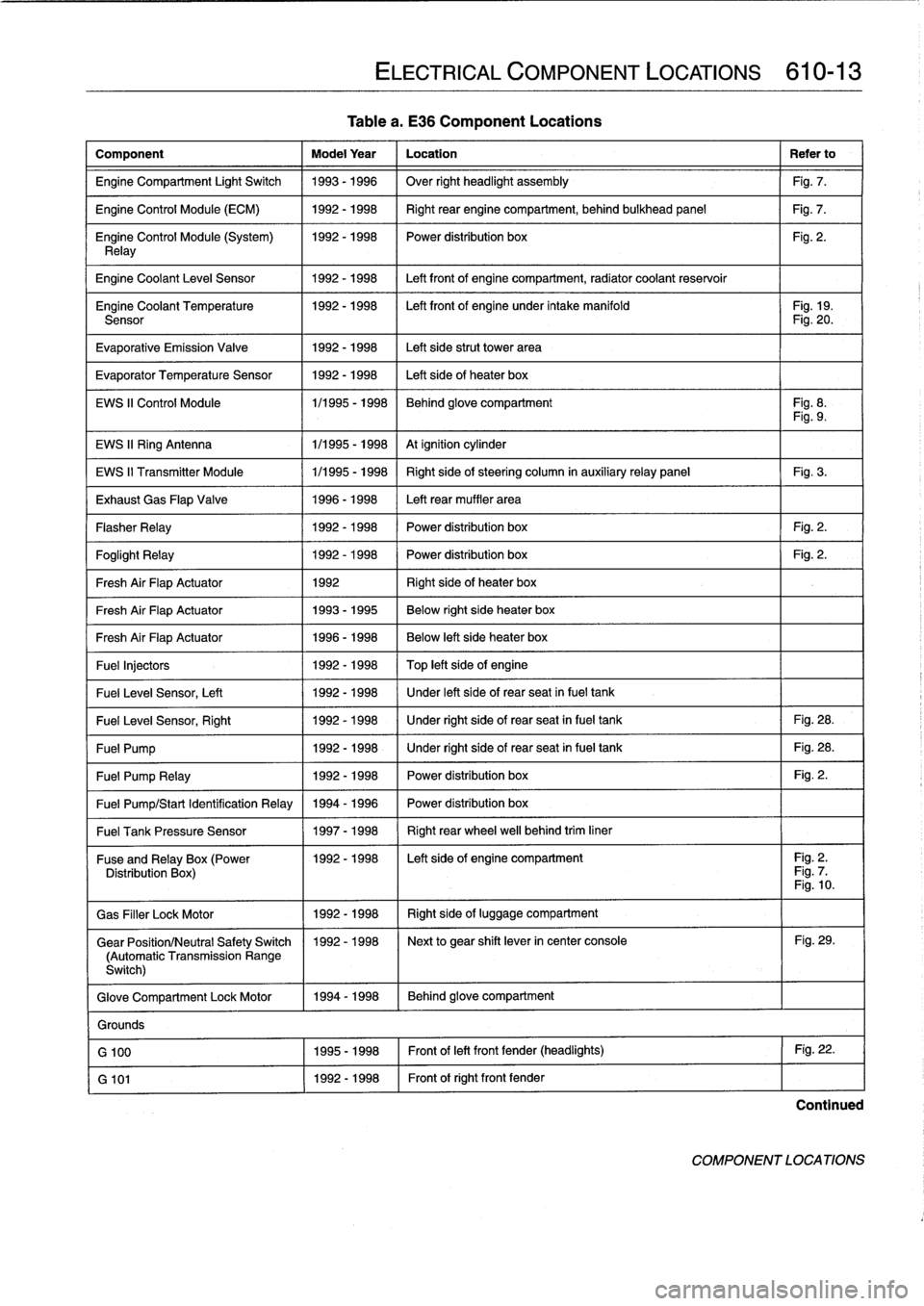
Tablea
.
E36
Component
Locations
Component
Model
Year
Location
Refer
to
Engine
Compartment
Light
Switch
1993-1996
Over
right
headlight
assembly
Fig
.
7
.
Engine
Control
Module
(ECM)
1992-1998
Right
rear
enginecompartment,
behind
bulkhead
panel
Fig
.
7
.
Engine
Control
Module
(System)
1992-1998
I
Power
distribution
box
Fig
.
2
.
Relay
Engine
Coolant
Leve¡
Sensor
1
1992-1998
1
Left
front
of
enginecompartment,
radiator
coolant
reservoir
Engine
Coolant
Temperature
1992-1998
I
Left
front
of
engine
under
intake
manifold
I
Fig
.
19
.
Sensor
Fig
.
20
.
Evaporative
Emission
Valve
1992-1998
Left
side
strut
Power
area
Evaporator
Temperature
Sensor
1992-1998
Left
side
of
heater
box
EWS
II
Control
Module
1/1995
-
1998
Behind
glove
compartment
Fig
.
8
.
Fig
.
9
.
EWS
II
Ring
Antenna
1
1/1995
-
1998
1
At
ignition
cylinder
EWS
II
Transmitter
Module
1/1995
-
1998
Right
side
of
steering
column
in
auxiliaryrelay
panel
Fig
.
3
.
Exhaust
Gas
Flap
Valve
1996-1998
Left
rear
muffler
area
Flasher
Relay
1992-1998
Power
distribution
box
Fig
.
2
.
Foglight
Relay
1
1992-1998
1
Power
distribution
box
1
Fig
.
2
.
Fresh
Air
FlapActuator
1
1992
1
Right
side
of
heater
box
Fresh
Air
FlapActuator
1
1993-1995
1
Below
right
side
heater
box
Fresh
Air
FlapActuator
1
1996-1998
Below
left
side
heater
box
Fuel
Injectors
1992
-
1998
Top
left
side
of
engine
Fuel
Leve¡
Sensor,
Left
1
1992-1998
/
Under
left
side
of
rear
seat
infuel
tank
Fuel
Leve¡
Sensor,
Right
1
1992-1998
1
Under
right
side
of
rear
seat
in
fuel
tank
1
Fig
.
28
.
Fuel
Pump
1
1992-1998
1
Under
right
side
of
rear
seat
in
fuel
tank
1
Fig
.
28
.
Fuel
Pump
Relay
1
1992-1998
1
Power
distribution
box
1
Fig
.
2
.
Fuel
Pump/Start
Identification
Relay
1994
-
1996
Power
distribution
box
Fuel
Tank
Pressure
Sensor
1
1997-1998
1
Right
rear
wheel
well
behind
trim
liner
ELECTRICAL
COMPONENT
LOCATIONS
610-13
Fuse
andRelay
x(Power
11992-1998
I
Left
side
of
engine
compartment
I
Fig
.
2
.
Distribution
Box
Fig
.
7
Fig
.
10
.
Gas
Filler
LockMotor
1992-1998
Right
side
of
luggage
compartment
Gear
Position/Neutral
Safety
Switch
1992-1998
Next
to
gear
shift
lever
in
center
console
Fig
.
29
.
(Automatic
Transmission
Range
Switch)
Glove
Compartment
Lock
Motor
1994-1998
Behind
glove
compartment
Grounds
G
100
1995-1998
Front
of
left
front
fender
(headlights)
Fig
.
22
.
G
101
1992-1998
Front
of
right
front
fender
Continued
COMPONENT
LOCATIONS
Page 405 of 759
FUSE
POSITION
TABLES
Table
b
through
Table
g
list
fuse
positions
in
the
power
dis-
tribution
box
and,
where
applicable,
in
the
auxiliary
relay
pan-
el,
the
left
side
splice
panel
and
the
luggage
compartment
.
Refer
to
the
beginning
ofthis
repair
group
for
locations
of
these
panels
.
ELECTRICAL
COMPONENT
LOCATIONS
610-19
FUSE
POSITION
TABLES
Page 407 of 759
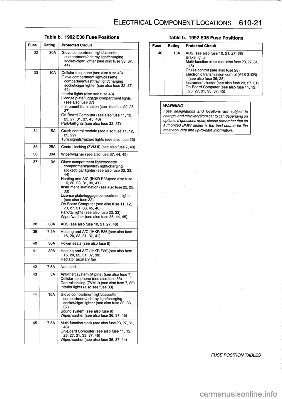
Table
b
.
1992
E36
Fuse
Positions
Table
b
.
1992
E36
Fuse
Positions
Fuse
Rating
Protected
Circuit
32
30A
Glove
compartment
light/cassette
compartmenVashtray
light/charging
socket/cigar
lighter
(see
also
fuse
33,37,
44)
33
10A
Cellular
telephone
(seealsofuse
43)
Glove
compartment
light/cassette
compartment/ashtray
IighUcharging
sockeUcigar
lighter
(seealsofuse
32,
37,
44)
Interiorlights
(also
see
fuse
43)
License
plate/luggage
compartment
lights
(see
also
f
use
37)
Instrument
íllumination
(see
also
fuse
22,25,
37)
On-Board
Computer
(see
also
fuse
11,12,23,27,31,37,45,
46)
Park/taillights
(seealso
fuse
22,
37)
34
15A
~
Crash
control
module
(see
also
fuse
11,
12,
25,29)
Turn
signals/hazard
lights
(seealsofuse
23)
35
1
25A
j
Central
locking
(ZVM
II)
(see
alsofuse
7,
43)
36
1
30A
1
Wiper/washer
(seealsofuse
37,44,
45)
37
10A
Glove
compartment
IighUcassette
compartmenVashtray
light/charging
socket/cigar
lighter
(see
also
fuse
32,33,
44)
Heating
andA/C
(IHKR
E36)(see
alsofuse
16,
20,23,31,
39,41)
Instrument
illumination
(see
also
fuse
22,25,
33)
License
plate/luggage
compartment
lights
(see
also
fuse
33)
On-Board
Computer
(see
also
fuse
11,12,23,27,31,33,45,
46)
Park/taillights
(see
alsofuse
22,
33)
Wiper/washer
(see
also
fuse
36,
44,
45)
38
1
30A
1
ABS
(see
also
fuse
10,21,27,
46)
39
7
.5A
Heating
andA/C
(IHKR
E36)(see
also
fuse
16,20,
23,
31,37,
41)
40
1
30A
1
Power
seats
(see
also
fuse
5)
41
30A
~
Heating
andA/C
(IHKR
E36)(see
alsofuse
16,20,23,
31,
37,
39)
Radiator
auxiliary
fan
42
I
7
.5A
I
Not
used
43
5A
Anti-theft
system
(Alpine)
(see
also
fuse
7)
Cellular
telephone
(seealsofuse
33)
Centrallocking
(ZVM
II)
(see
also
f
use
7,
35)
Interiorlights
(also
see
fuse
33)
44
15A
Glove
compartment
light/cassette
compartmenVashtray
light/charging
sockeUcigar
lighter
(see
also
fuse
32,
33,
37)
Sound
system
(see
also
fuse
9)
Wiper/washer
(see
also
fuse
36,37,
45)
45
7
.5A
Multi-function
clock
(see
also
fuse
23,
27,
31,
46)
On-Board
Computer
(see
also
fuse
11,12,
23,
27,31,33,
37,46)
Wiper/washer
(see
also
fuse
36,37,
44)
ELECTRICAL
COMPONENT
LOCATIONS
610-21
Fuse
Rating
Protected
Circuít
46
15A
ABS
(see
also
fuse
10,21,27,
38)
Brake
lights
Multi-function
clock
(seealso
fuse
23,27,31,
45)
Cruise
control
(see
also
fuse
28)
Electronic
transmission
control
(A4S
310R)
(see
also
f
use
26,
28)
Instrument
cluster
(seealsofuse
23,
27,31)
On-Board
Computer
(see
also
f
use
11,12,
23,
27,31,33,
37,45)
WARNING
-
Fuse
designations
and
locations
are
subject
to
change,
and
may
vary
from
car
tocar,
depending
on
options
.
If
questions
arise,
please
remember
that
an
authorized
BMW
dealer
is
the
best
source
for
the
most
accurate
and
up-to-date
information
.
FOSE
POSITION
TABLES
Page 409 of 759
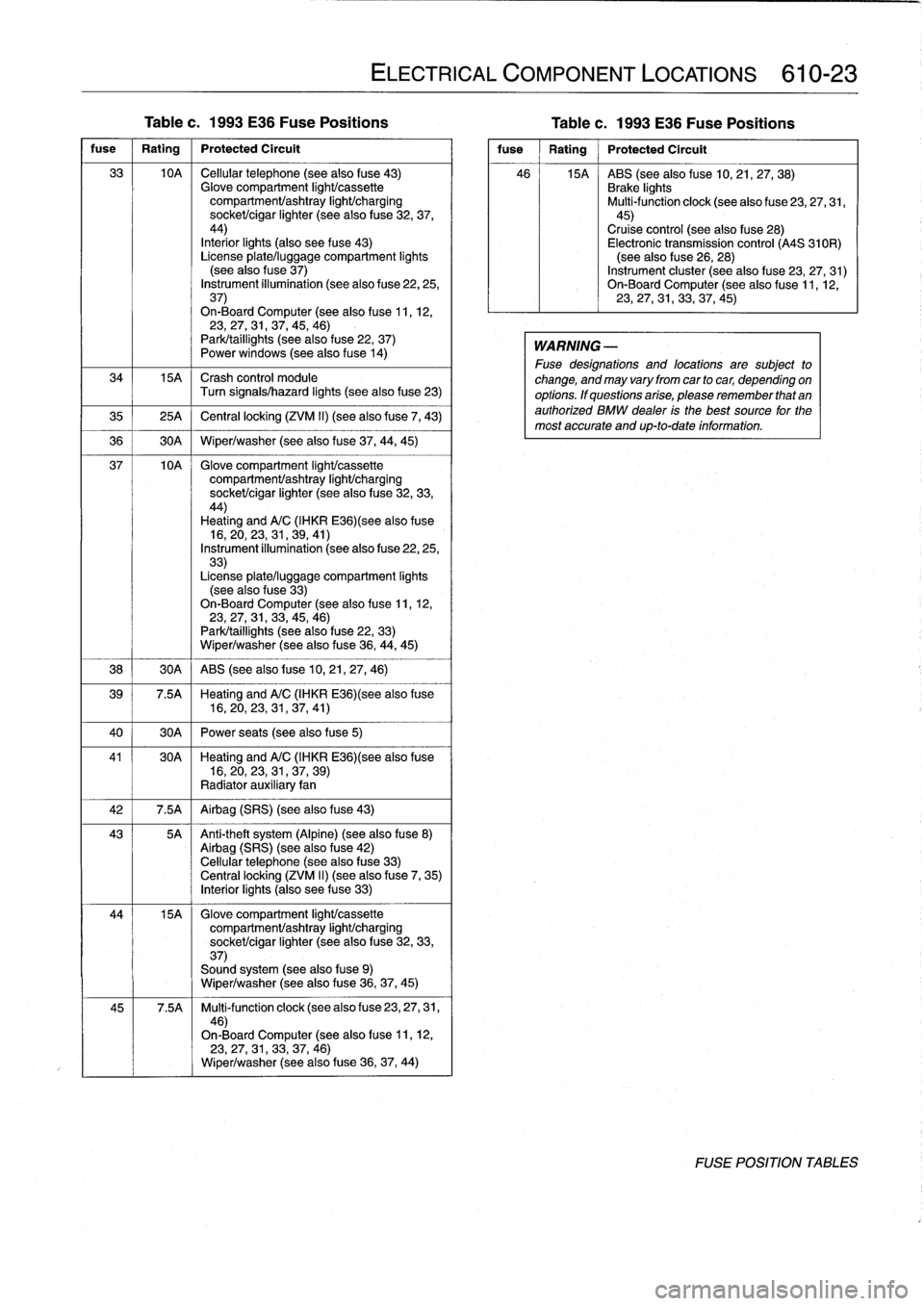
Table
c
.
1993
E36
Fuse
Positions
Table
c
.
1993
E36
Fuse
Positions
fuse
1
Rating
1
Protected
Circuit
33
10A
Cellular
telephone
(see
also
fuse
43)
Glove
compartment
IighUcassette
compartment/ashtray
light/charging
socket/cigar
lighter
(seealsofuse
32,37,
44)
Interior
lights
(also
see
fuse
43)
License
plate/luggage
compartment
lights
(seealsofuse
37)
Instrument
illumination
(see
also
fuse
22,
25,37)
On-BoardComputer
(seealso
f
use
11,
12,23,27,31,
37,
45,
46)
Park/taillights
(seealso
fuse
22,
37)
Powerwindows
(see
also
f
use
14)
34
15A
Crash
control
module
Turn
signals/hazard
lights
(seealsofuse
23)
35
1
25A
1
Central
locking
(ZVM
II)
(seealso
fuse
7,
43)
36
1
30A
1
Wiper/washer
(see
alsofuse
37,
44,
45)
37
10A
Glove
compartment
light/cassette
compartmenUashtray
IighUcharging
socket/cigar
lighter
(see
also
fuse
32,33,44)
Heating
and
A/C
(IHKR
E36)(see
alsofuse
16,20,23,
31,
39,
41)
Instrument
illumination
(seealso
fuse
22,25,33)
License
plate/luggage
compartment
lights
(seealsofuse
33)
On-BoardComputer
(seealsofuse
11,12,
23,
27,31,
33,
45,
46)
Park/taillights
(see
also
fuse
22,
33)
Wiper/washer
(seealsofuse
36,
44,
45)
38
1
30A
1
ABS
(seealso
f
use
10,21,27,
46)
39
7
.5A
Heating
and
A/C
(IHKR
E36)(see
alsofuse
16,20,23,
31,
37,
41)
40
1
30A
1
Power
seats
(see
also
fuse
5)
41
30A
~
Heating
and
A/C
(IHKR
E36)(see
alsofuse
16,20,23,
31,
37,
39)
Radiator
auxiliary
fan
42
1
7.5A
1
Airbag
(SRS)
(seealsofuse
43)
43
5A
Anti-theft
system
(Alpíne)
(seealsofuse
8)
Airbag
(SRS)
(seealsofuse
42)
Cellular
telephone
(see
also
fuse
33)
Central
locking
(ZVM
II)
(seealso
f
use
7,
35)
Interiorlights
(also
see
fuse
33)
44
15A
Glove
compartment
IighUcassette
compartment/ashtray
IighUcharging
sockeUcigar
lighter
(seealsofuse
32,33,
37)
Sound
system
(see
alsofuse9)
Wiper/washer
(see
also
fuse
36,
37,
45)
45
7
.5A
Multi-function
clock
(seealso
fuse
23,
27,
31,
46)
On-BoardComputer
(see
also
f
use
11,12,23,27,31,33,37,
46)
Wiper/washer
(see
also
fuse
36,37,
44)
ELECTRICAL
COMPONENT
LOCATIONS
610-23
fuse
Rating
Protected
Circuit
46
15A
ABS
(see
alsofuse
10,
21,27,38)
Brake
lights
Multi-function
clock
(seealso
fuse
23,
27,
31,
45)
Cruise
control
(see
also
fuse
28)
Electronic
transmission
control
(A4S
310R)
(see
also
fuse
26,
28)
Instrument
cluster
(see
alsofuse
23,27,
31)
On-BoardComputer
(see
also
f
use
11,
12,
23,
27,31,33,37,
45)
WARNING
-
Fuse
designations
and
locations
are
subject
to
change,
and
may
vary
from
car
tocar,
depending
on
options
.
Ifquestionsarise,
pleaserememberthatan
authorized
BMW
dealer
is
the
best
source
for
the
most
accurate
and
up-to-date
information
.
FOSE
POSITION
TABLES
Page 411 of 759
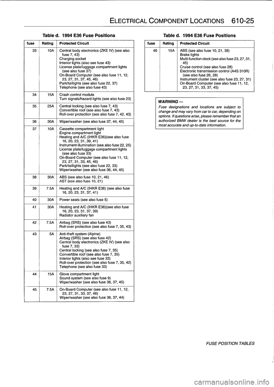
ELECTRICAL
COMPONENT
LOCATIONS
610-25
Table
d
.
1994
E36
Fuse
Positions
Table
d
.
1994
E36
Fuse
Positions
fuse
1
Rating
1
Protected
Circuit
33
10A
Central
body
electronics
(ZKE
IV)
(seealso
Puse
7,
43)
Charging
socket
Interiorlights
(also
see
fuse
43)
License
platelluggage
compartment
lights
(seealsofuse
37)
On-BoardComputer
(seealso
fuse
11,12,
23,27,
31,37,
45,
46)
Park/taillights
(seealso
fuse
22,
37)
Telephone
(see
also
fuse
43)
34
15A
Crash
control
module
Turn
signals/hazard
lights
(seealsofuse
23)
35
25A
~
Central
locking
(seealso
fuse
7,
43)
Convertible
roof
(see
also
fuse
7,
43)
Roll-over
protection
(see
alsofuse
7,
42,
43)
36
j
30A
1
Wiper/washer
(see
alsofuse
37,
44,
45)
37
10A
Cassette
compartment
light
Engine
compartment
light
Heating
andA/C
(IHKR
E36)(see
alsofuse
16,20,23,
31,
39,
41)
Instrument
illumínation
(see
also
fuse
22,
25)
License
plate/luggage
compartment
lights
(seealso
f
use
33)
On-BoardComputer
(seealso
fuse
11,
12,23,27,
31,33,
45,
46)
Park/taillights
(seealso
fuse
22,
33)
Wiper/washer
(see
alsofuse
36,
44,45)
38
30A
ABS
(see
also
fuse
10,21,
46)
AST
(see
also
fuse
10,
21)
39
7
.5A
Heating
andA/C
(IHKR
E36)(see
also
fuse
16,20,23,
31,
37,
41)
40
1
30A
1
Power
seats
(seealsofuse
5)
41
30A
~
Heating
andA/C
(IHKRE36)(see
also
fuse
16,20,
23,31,
37,
39)
Radiator
auxiliary
fan
42
7.5A
Airbag
(SRS)
(seealsofuse
43)
Roll-over
protection
(see
also
f
use
7,
35,
43)
43
5A
Anti-theft
system
(Alpine)
Airbag
(SRS)
(see
also
fuse
42)
Central
body
electronics
(ZKE
IV)
(see
also
fuse
7,
33)
Central
locking
(seealsofuse
7,
35)
Convertible
roof
(see
alsofuse
7,
35)
Interior
lights
(also
see
fuse
33)
Rol¡-over
protection
(seealsofuse
7,
35,
42)
Telephone
(seealsofuse
33)
44
15A
~
Glove
compartment
light
Sound
system
(see
also
f
use
9)
Wiper/washer
(see
also
fuse
36,
37,
45)
45
7
.5A
~
On-Board
Computer
(see
also
fuse
11,12,23,
27,
31,33,37,
46)
Wiper/washer
(see
also
fuse
36,37,
44)
fuse
1
Rating
1
Protected
Circuit
46
15A
ABS
(see
also
fuse
10,21,
38)
Brake
lights
Multi-function
clock
(see
also
fuse
23,
27,
31,45)Cruise
control
(seealsofuse
28)
Electronic
transmission
control
(A4S
310R)
(seealsofuse
26,
28)
Instrument
cluster
(see
also
fuse
23,
27,31)
On-Board
Computer
(see
also
fuse
11,12,23,27,31,33,37,
45)
WARNING
-
Fuse
designations
and
locations
are
subject
to
change
and
may
varyfrom
car
tocar,
depending
on
options
.
If
questions
arise,
please
remember
that
an
authorized
BMW
dealer
is
the
best
source
for
the
most
accurate
and
up-to-date
information
.
FOSE
POSITION
TABLES
Page 413 of 759
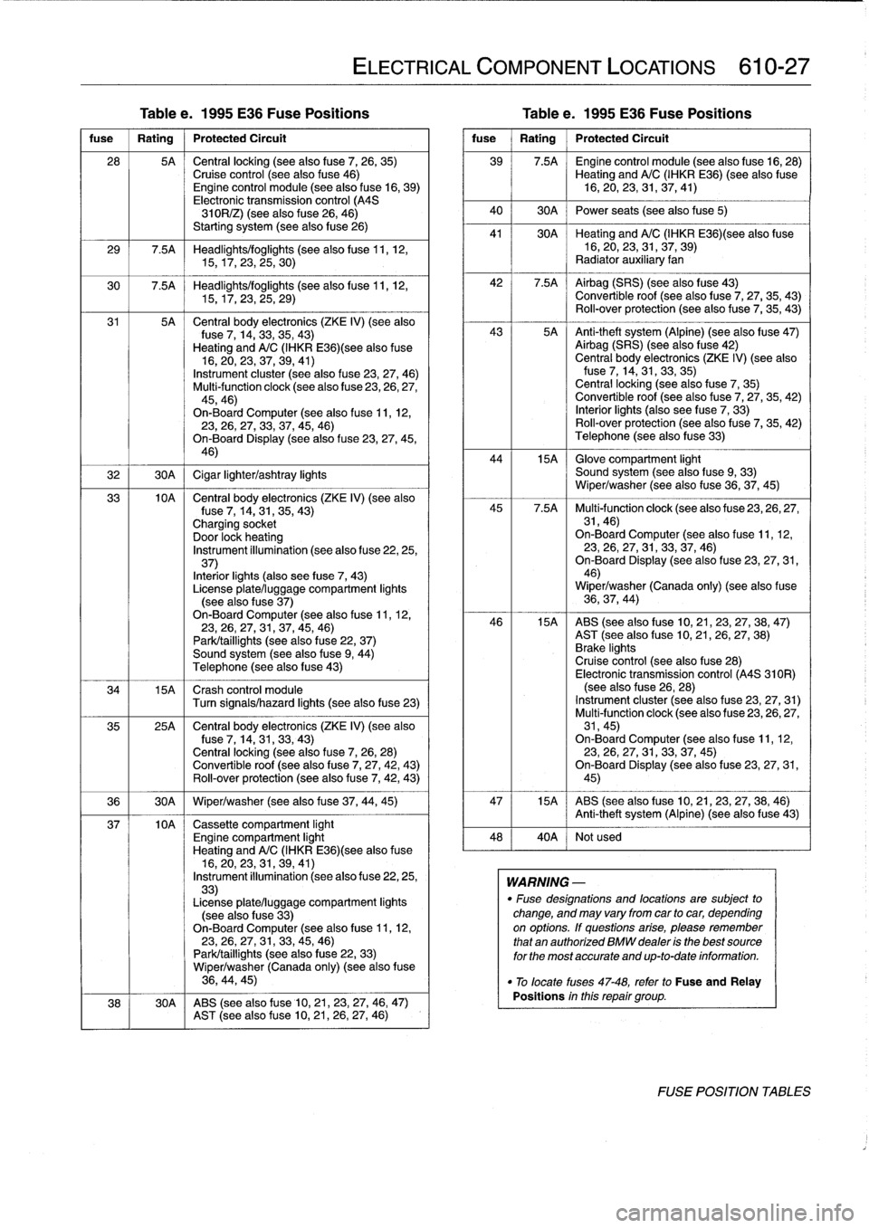
Tablee
.
1995
E36
Fuse
Positions
Table
e
.
1995
E36
Fuse
Positions
fuse
I
Rating
1
Protected
Circuit
28
5A
Central
locking
(see
alsofuse
7,
26,
35)Cruise
control
(see
also
fuse
46)Engine
control
module
(see
also
f
use
16,
39)
Electronic
transmission
control
(A4S
310R/Z)
(see
also
f
use
26,
46)
Starting
system
(seealsofuse
26)
29
7.5A
Headlights/foglights
(seealsofuse
11,
12,
15,17,23,
25,30)
30
7
.5A
Headlights/foglights
(seealsofuse
11,
12,
15,17,23,
25,29)
31
5A
Central
body
electronics
(ZKE
IV)
(see
also
fuse
7,
14,33,35,43)
Heating
and
A/C
(IHKR
E36)(see
also
fuse
16,20,23,
37,
39,
41)
Instrument
cluster
(see
also
fuse
23,27,
46)
Multi-function
clock
(see
also
fuse
23,26,27,
45,46)
On-Board
Computer
(seealso
f
use
11,
12,23,26,27,
33,
37,45,
46)
On-Board
Display
(seealso
f
use
23,27,45,
46)
32
1
30A
1
Cigar
lighter/ashtray
lights
33
10A
Central
body
electronics
(ZKE
IV)
(see
also
fuse
7,
14,31,35,
43)
Charging
socket
Door
lock
heating
Instrument
illumination
(see
also
fuse
22,25,
37)
Interiorlights
(also
see
fuse
7,
43)
License
plate/luggage
compartment
lights
(see
alsofuse
37)
On-Board
Computer
(seealsofuse
11,
12,23,26,27,
31,
37,45,
46)
Park/taillights
(see
also
f
use
22,
37)
Sound
system
(see
also
fuse
9,
44)
Telephone
(see
alsofuse
43)
34
15A
Crash
control
module
Turn
signals/hazard
lights
(see
also
fuse
23)
35
25A
Central
body
electronics
(ZKE
IV)
(see
also
f
use
7,
14,31,
33,43)
Central
locking
(seealso
f
use
7,
26,
28)
Convertible
roof
(see
alsofuse
7,
27,42,
43)
Rol¡-over
protection
(see
alsofuse
7,
42,
43)
36
1
30A
1
Wiper/washer
(see
alsofuse
37,
44,
45)
37
10A
Cassette
compartment
light
Engine
compartment
light
Heating
and
A/C
(IHKR
E36)(see
alsofuse
16,20,23,
31,
39,
41)
Instrument
illumination
(seealsofuse
22,25,
33)
License
plate/luggage
compartment
lights
(see
also
fuse
33)
On-Board
Computer
(see
alsofuse
11,
12,23,26,
27,
31,33,45,
46)
Park/taillights
(see
alsofuse
22,
33)
Wiper/washer
(Canada
only)
(see
also
f
use
36,
44,45)
38
30A
ABS
(see
also
fuse
10,21,23,
27,
46,
47)
AST
(see
alsofuse
10,
21,
26,27,
46)
ELECTRICAL
COMPONENT
LOCATIONS
610-27
fuse
Rating
Protected
Circuit
39
7.5A
~
Engine
control
module
(see
alsofuse
16,28)
Heating
and
A/C(IHKR
E36)(see
also
fuse
16,20,23,
31,
37,
41)
40
1
30A
1
Power
seats
(see
alsofuse5)
41
30A
~
Heating
and
A/C(IHKRE36)(see
also
fuse
16,20,
23,31,
37,
39)
Radiator
auxiliary
fan
42
7
.5A
~
Airbag
(SRS)
(see
also
fuse
43)
Convertible
roof
(see
alsofuse
7,
27,
35,
43)
Rol¡-over
protection
(see
also
fuse
7,
35,
43)
43
5A
Anti-theft
system
(Alpine)
(seealsofuse
47)
Airbag
(SRS)
(see
also
fuse
42)
Central
body
electronics
(ZKE
IV)
(seealsofuse
7,
14,31,33,35)
Central
locking
(seealsofuse
7,
35)
Convertible
roof
(see
alsofuse
7,
27,
35,
42)
Interior
lights
(also
see
fuse
7,
33)
Roll-over
protection
(see
alsofuse
7,
35,42)
Telephone
(seealsofuse
33)
44
15A
~
Glove
compartment
light
Sound
system
(see
also
f
use
9,
33)
Wiper/washer
(see
alsofuse
36,37,
45)
45
7
.5A
Multi-function
clock
(see
also
fuse
23,
26,27,
31,46)
On-Board
Computer
(see
also
f
use
11,12,23,26,
27,31,
33,37,
46)
On-Board
Display
(seealso
fuse
23,27,31,
46)
Wiper/washer
(Canada
only)
(seealsofuse
36,37,
44)
46
15A
ABS
(seealsofuse
10,21,23,27,
38,47)
AST
(seealso
fuse
10,
21,
26,
27,
38)
Brake
lights
Cruise
control
(see
also
fuse
28)
Electronic
transmission
control
(A4S
310R)
(seealsofuse
26,
28)
Instrument
cluster
(see
also
fuse
23,
27,
31)
Multi-function
clock
(see
also
fuse
23,
26,27,
31,45)
On-BoardComputer
(seealsofuse
11,
12,
23,26,
27,31,
33,37,
45)
On-Board
Display
(see
also
fuse
23,27,31,
45)
47
15A
ABS
(see
also
fuse
10,21,23,27,38,
46)
Anti-theft
system
(Alpine)
(see
alsofuse
43)
48
40A
Notused
WARNING
-
"
Fuse
designations
and
locations
are
subject
to
change,
and
may
varyfrom
car
tocar,
depending
on
options
.
lf
questions
arise,
please
remember
that
an
authorized
BMW
dealer
is
the
best
source
for
the
most
accurate
and
up-to-date
information
.
"
To
locate
fuses
47-48,
refer
to
Fuse
and
Relay
Positions
inthis
repair
group
.
FOSE
POSITION
TABLES