automatic BMW M3 1998 E36 Workshop Manual
[x] Cancel search | Manufacturer: BMW, Model Year: 1998, Model line: M3, Model: BMW M3 1998 E36Pages: 759
Page 661 of 759
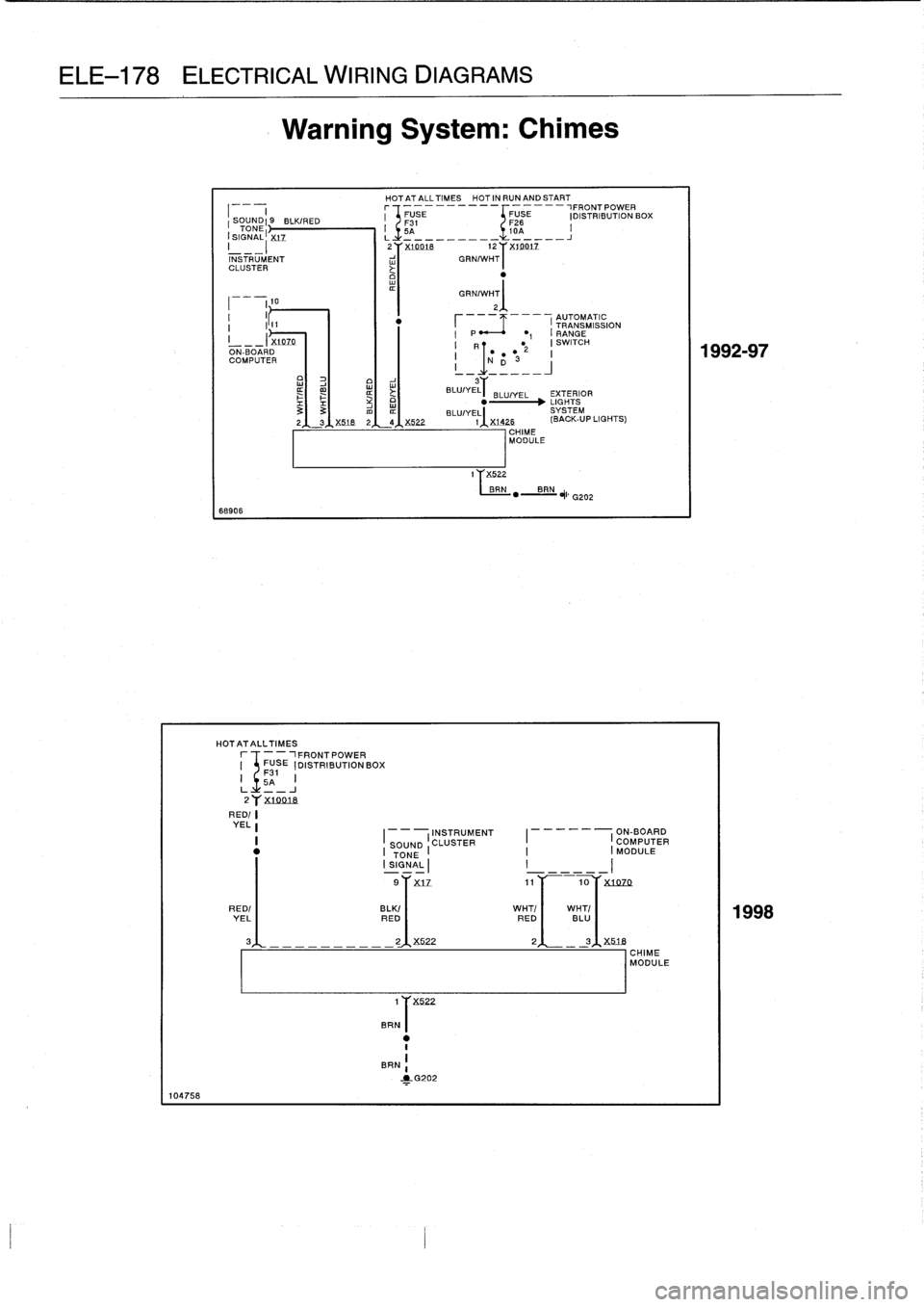
ELE-178
ELECTRICAL
WIRING
DIAGRAMS
104758
68906
HOTATALLTIMES
--
_1
FRONT
POWER
FUSE
[DISTRIBUTION
BOX
F31
5A
I
J
2y
X70018
Warning
System
:
Chimes
HOTATALLTIMES
HOTINRUNANDSTART
r
-
N"
FUSE
I
SOU9
BLK/RED
F31
TONE
I
I
5A
(SIGNAL
XL7
.
L
___
__
2''X
10018
1
z
}'
X14912
INSTRUMENT
w
GRN/WHT
CLUSTER
Y
1
T
X522
BRN
-2-G202
I
1
GRN/w
10
r12
T
t
I
I
---
---
AUTOMATIC
I
111
TRANSMISSION
I
I
P
~
1
I
RANGE
__-
X14
Z0
I
R
t
(SWITCH
ON-BOARD
I
T
-
12
I
COMPUTE
i
-
IND3
--
~
o
w
3
BLU/YEL
.
BLU/-
YEL
EXTERIOR
33
m
LIGHTS
BLU/YEL
SYSTEM
2
3
X518
2
4
X522
I
X1426
(BACK-UP
LIGHTS)
CHIME
MODULE
1FRONTPOWER
FUSE
F26
(DISTRIBUTION
BOX
10A
I
J
1
X522
BRN
rB
RN
*
G202
RED/
YELL
INSTRUMENT
ON-BOARD
I
I(
CLUSTER
COMPUTER
I
SOUND
I
TONE
I
MODULE
SIGNAL
I
I
9
X17
11
~~
10
X1070
BLK/
RED
2
X522
RED/
I
WHT/
I
WHT/
YEL
RED
BLU
3
,1
.
---------
3~M_7B
CHIME
MODULE
Page 679 of 759
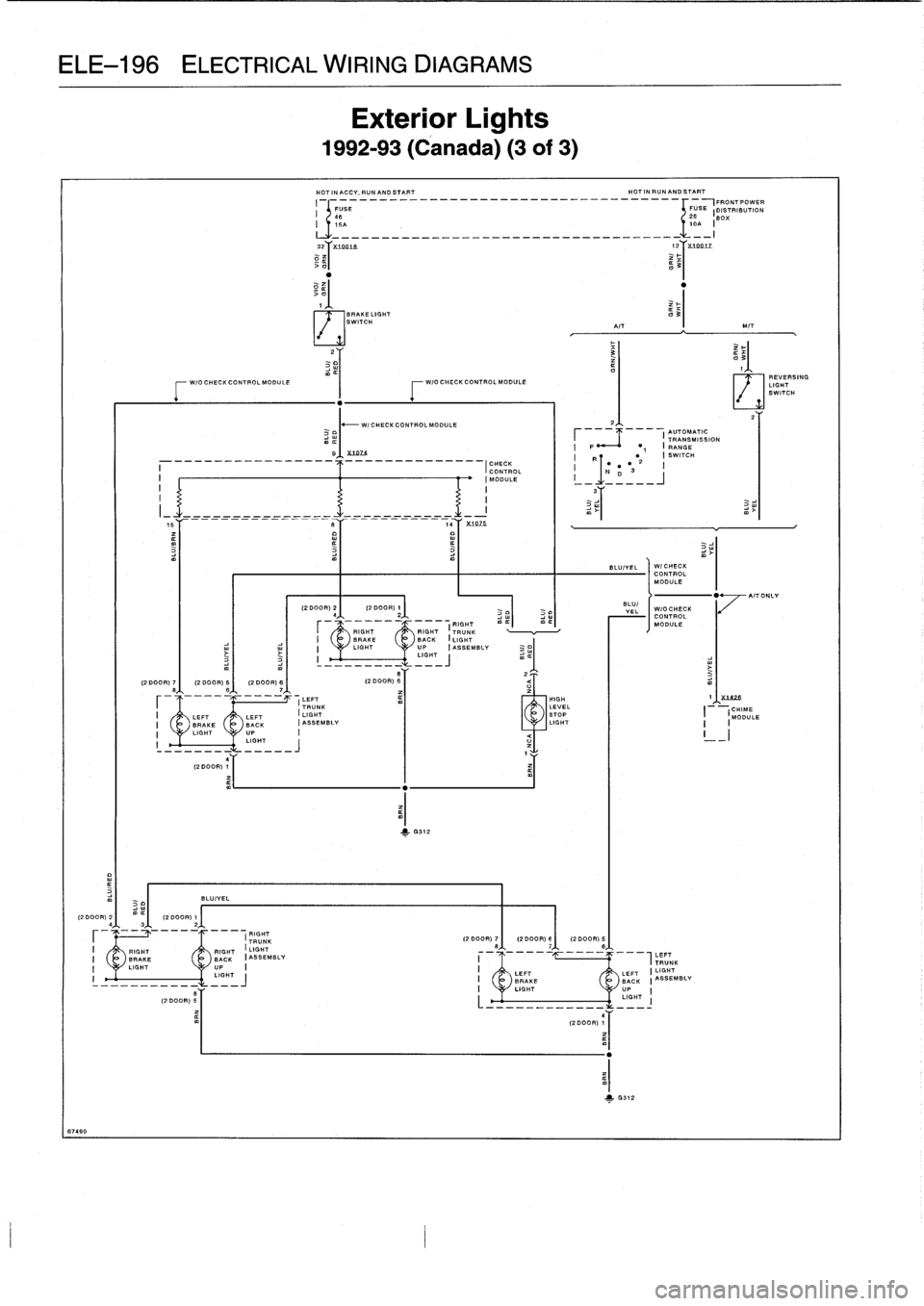
ELE-196
ELECTRICAL
WIRING
DIAGRAMS
67490
F
W/OCHECICONTROLMODULE
F
W/0
CHECK
CONTROL
MODULE
S
(2
DOOR)
5
RIGHT
I
LIGHT
BACK
(ASSEMBLY
I
RIGHT
TRUNK
Exterior
Lights
1992-93
(Canada)
(3of3)
HOT
IN
ACCY,
RUNANO
START
HOT
IN
RUNAND
START
I
I
SE
-------------------------------r+
FUSE,FRONTPOWER
FN
[S
(J
~
DISTRIBUTION
I
T15A
OA
BOX
,
---_-____-__________________-_-_
-
```
I
LLL
I
>
o
~'ui62i
.B
XI201Z
3
~2
12
o
t
BRAKE
LIGHT
O
3I
SWITCH
AIT
MIT
2,1,
I
AUTOMATIC
TRANSMISSION
I
P
~
I
RANGE
1
R
I
SWITCH
2
I
I
1Np
"3
BLUIYEL
1
G312
WICHECKCONTROLMODULE
WIOCHECKCONTROLMODULE
LEFT
I
LIGHT
BACK
(ASSEMBLY
UP
I
LIGHT
,
1
351925
,CHIME
,MODULE
1
4
1
REVERSING
LIGHT
SWITCH
AIT
ONLY
Page 682 of 759
67479
(2DOOR)
2f
-12
DOOR)1
43
2
BLU/VEL
LIGHT
UP
I
I
--------
------
11"
,
j
(RIGHTTRUNK
I
RIGHT
RIGHT
I
LIGHT
I
BRAKE
BACK
IASSEMBLV
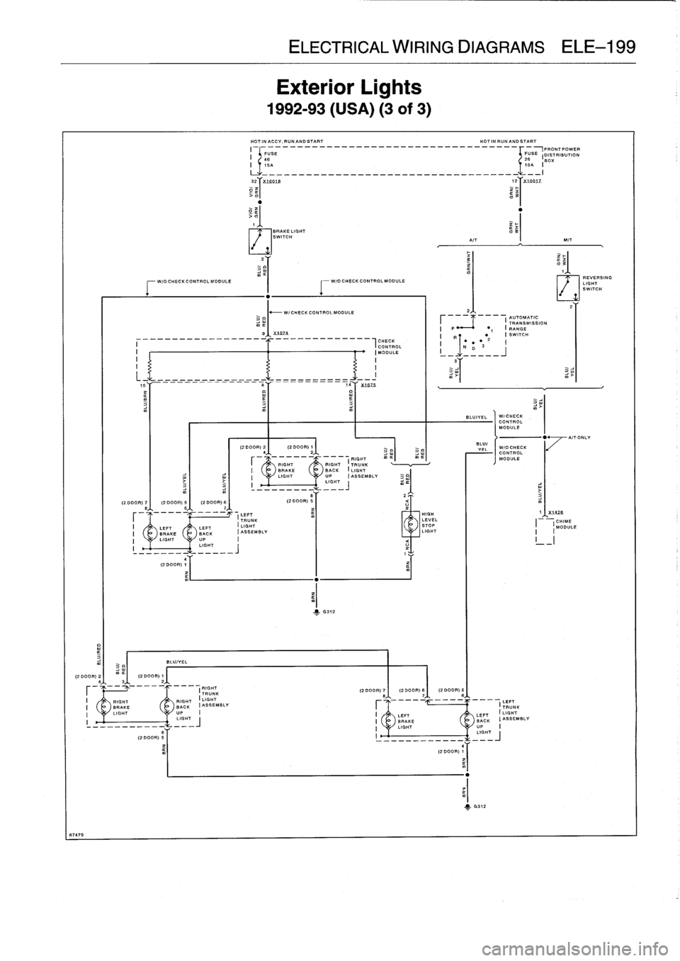
Exterior
Lights
1992-93
(USA)
(3
of
3)
HOT
INACCV,SUNANDSTART
HOTINRUNANDSTART
I
I
-------------------------------
FUS~FRONTPOWER
FUSE
25
181
0
5%RIBUTION
C6
I
15A
10A
II
--------------------------------------
32
X14419
12
X79R3Z
>
~
a
3~
>U
1
BRAKE
LIGHT
~3I
SWITCH
A/T
MIT
2
W/0
CHECK
CONTROLMODULE
W/O
CHECK
CONTROLMODULE
-
W/CHECKCONTROLMODNLE
m
e~
X
107<
-_______
_____________
CHECKCONTROL
I
(MODULE
I
II
I
T1"
--rrrrrr--rrrrrr___--cc---a
X
14775
ELECTRICAL
WIRING
DIAGRAMS
ELE-199
BLU/
T
=
L
I
CONTROL
CONTROL
_
I
RIGHT
MODULE
RIGHT
TRUNK
BACK
I
LIGHT
UP
ASSEMBLY
LIGHT~
t
1
6312
HIGH
LEVEL
STOP
LIGHT
2,L,
AUTOMATIC
~
TRANSMISSION
I
P~^
~
I
RANGE
1
I
R
1
SWITCH
2
II
N
p"
3
(2DOOR)
7
(2DOOR)B~
(2DOOR)
5~
5
LEFT
TRUNK
I
LEFT
LEFT
I
LIGHT
I
BRAKE
BACK
IASSEMBLY
I
LIGHT
UP
I
S
LIGHT
(2
DOOR)
5
I
I
_-----_----
_
_
(2DOOR)
1
BLU/VEL
-/CHECK
CONTROL
MODULE
m
1
1
X1A2B
j
REVERSING
LIGHT
SWITCH
E3
-.
I
I
CHIME
I(
MODULE
I
_I
A/TONLV
Page 685 of 759
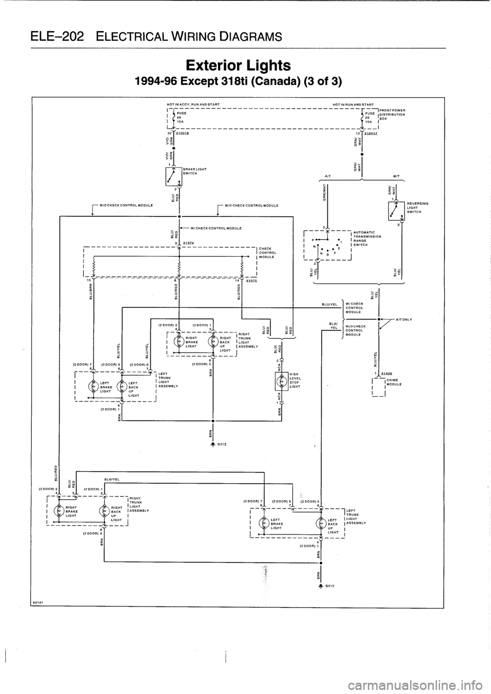
ELE-202
ELECTRICAL
WIRING
DIAGRAMS
8314
1
(2
.
.OF)
S
l
.
m
3
(2DOOR)
Ply
(2
DOOR)
7
I
(2
DOOR)
5
I
(2
DOOR)
6
r
IIII
m
3
3
F
WIOCHECKCONTROL
MODULE
I-
W/O
CHECK
CONTROLMODULE
4
T
I
(2
DOOR)
TL
BLUIVEL
Exterior
Lights
1994-96
Except
318ti
(Canada)
(3
of
3)
HOT
IN
ACCV,
RUN
AND
START
HOT
IN
RUN
AND
START
I
FUSE
------------__---_-------------{FUS
DISTRIBUTION46
26
BOX
32
X
10016
12
X14DIZ
>u
~
3~
1
BRAKE
LIGHT
SWITCH
-
WI
CHECK
CONTROLMODULE
RI
HT
TRU
In~unN'--I
--1
RIGHT
GK
I
BRAKE
BACK
I
LIGHT
I
LIGHT
UP
ASSEMBLY
I
L,
CH,
~
m
B
Y
(2
DOOR)
3
2
2
U
ZT
(2
DOOR)
9
(2
DOOR)
7)(2
DOOR)
6~
l
.,
m
4TT
(2
DOOR)
¢I
2,1,
I
AUTOMATIC
I
-
TRANSMISSION
I
P
I
gAN
..
1
0312
B~
X
1074
I
q
I
SWITCH
._-
._---------
_-
.
.
..
.-------
CHECK
2
I(
CONTROL
ND3
-
I
I
MODULE
I
-
----
I
1
I
I
BLU/VEL
I
W/CHECK
CONTROL
MODULE
(2000R)
41
-
(2000)A)
2l
.
BLU(
I
VEL
WIOCHECK
CONTROL
MODULE
'7`
I
LEFT
1.
F
-
1
-
1
HIGH
1
X7426
TRUNK
SEA
L
I
(CHIME
LEFT
LEFT
I
LIGHT
MODU
K
I
ASSEMBLY
T
BRAKE
BAC
LIGHT
I(
LE
LIGHT
__
LIGHT
I
~
LEFT
I
TRUNK
LEFT
LEFT
I
LIGHT
I
BRAKE
BACK
(ASSEMBLY
I
LIGHT
UP
I
LIGHT
I
"
4~PIT
ONLY
REVERSING
LIGHT
SWITCH
Page 688 of 759
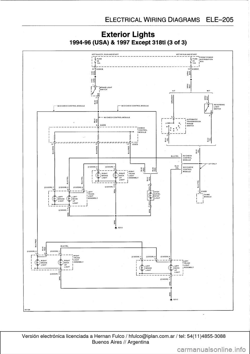
(2DOOR)
2I
1
(2DOOR)1
4
3
2
,
8313
8
(2
DOOR)
78
1
(2
DOOR)
61
(2
DOOR)
B~
-
-
-
-
-
-
-
--
-
-
-
-
4(2
DOOR)
1
BLUIVEL
I
RIGHT
RIGHT
I
LIGHT
I
BRAKE
BACK
IABSEMBLV
I
LIGHT
UP
I1
---------------
GHT
8
(2
DOOR)
B
Exterior
Lights
1994-96
(USA)
&
1997Except
318ti
(3
of
3)
HOTINACCY,RUNANDSTART
HOTINRUNANDSTART
II
-------------------------------+FUS~FRONTPOWER
FUSE
DISTRIBUTION
46
26
16A
l
.A
I
___________________________-_-___
_-I
32
X
IDDtn
12
X10017_
0
»i
a3T
2
WIOCHECKCONTROLMODULE
W/OCHECKCONTROLMODULE
I
-----------------
LEFT
TRUNK
BRAKE
BACK
IABSEMBLV
LIGHT
UP
I
LIGHT
_____J
9
1
X
1n74
---------
-_-__-----------
iaY
x107
ELECTRICAL
WIRING
DIAGRAMS
ELE-205
BRAKE
LIGHT
v
3
(
SWITCH
I
I
A/T
!
_
ZJ
-
W/CHECK
CONTROL
MODULE
--------------I
CHECK
CONTROLIMOOULE
1
6312
1
RIGHT
RIGHT
TRUNKBRAKE
BACK
(LIGHT
I
LIGHT
UP
IABSEMBLV
m
i
LIGHT
j
(2
DOOR)
B
2
=T
RIGHT
(2
DOOR)
7
1
(2
DOOR)
6I
(2
DOOR)
6
TRUNK
HIGH
LEVEL
STOP
LIGHT
BLUIVEL
(2DOOR)
2
(2DCOF)1
VEL
[WIOCHECK
4
2
CONTROL
---------_---
(G
m¢
m
¢I
RIHT
MODULE
BLU/
2
I
AUTOMATIC
TRANSMISSION
I
P
"
1
I
RANGE
I
R
I
SWITCH
"2
I
D
I
3
WICHECK
CONTROL
MODULE
X732fi
I
CHIME
MODULE
I
I
LEFT
LEFT
I
LIGHT
AIT
ONLY
Page 691 of 759
ELE-208
ELECTRICAL
WIRING
DIAGRAMS
88603
4
(2DOOR)
1
HOTINACCV,PUNANDSTART
HOTINRUNANDSTART
r
-5E---_--__-------------
._____-___--------
FUSE
FRONTPOWER
26
I
DISTRIBUTION
BOX
IoA
I
Lk___--_______-____-_-_________-_-_-_-__---
X
tDD1e
12
X1oDu
>
all
of
1
2
323,
8~
17
3181
328.M3
15~
2
10
~--
1
CONTROL
.
T
I
_
__
_
_I
I
I
!
ON-BOARD
I
I
2,1,
I
I
!I
I
I
COMPUTER
I
AUTOMATIC
RANGE
6M168ION
i
-I
.I
I
-I
-I
I
P
~1
(
ABSCONTROL
BLIP
-
CONTROL
CRUISE
TRA
I
NSMISSION
I
R
I
SWITCHODULEI
HVDRAULICUNIT
MODULE
MODULE
CONTROLMODULE
i
N
D
S"2
~-
WICHECK
CONTROL
MODULEm
.
________9~X1074
(CHECK
CONTROL
(MODULE
!
I
'
S,
~,
4YX
[
1075
.
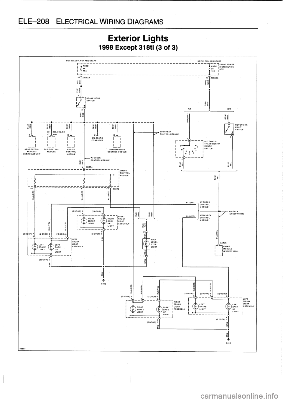
Exterior
Lights
1998
Except
318ti
(3
of
3)
BLUIYEL
WICHECKCONTROLMODULE
REVERSING
LIGHT
SWITCH
(2DOOR)
221
(2DOOR)
21
-
0
AITONLY
'
(EXCEPT
1998)
'F
RIGHT
BLUIYEL
WIOCHECK
RIGHT
RIGHT
l
7RUNN
`
CONTROL
I
BRAKE
BACK
(LIGHT
MODULE
-
!
LIGHT
UP
(ASSEMBLY
I
-,
.HT
(2
D
OR)
7
(2
DOOR)
5
(2
DOOR)
8
(2
DOOR)
5~
2
T
Q
88,{,
7A,
LEFT
HIGH
TRUNK
LEVEL
1
X1476
LEFT
LEFT
LIGHT
STOP
_
BRAKE
BACK
ASSEMBLY
LIGHT
(
!CHIME
LIGHT
UP
MODULE
LIGHT
Q
I
I
(EXCEPT
1998)
(2DOOR)
2~
(2DOOR)
7I
(2DOOR)
6I
(2DOOR)
5
(2DOOR)
1~
__--
2
LEFT
-
RIGHT
TRUNK
(
TRUNK
!
LEFT
LEFT(LIGHT
I
RIGHT
RIGHT
(LIGHT
I
BRAKE
BACK
:ASSEMBLY
I
BRAKE
~
BACK
(ASSEMBLY
I
LIGHT
UP
I!
LIGHT
UP
:
!
LIGHT-
!
LIGH=~
---_--_----
-_-
4
Y
y
II
(2
DOOR)
1
------
(2
DOOR)
¢1
1
G312
Page 702 of 759
EXTERIOR
LIGHTS
SYSTEM
(TURN/HAZARD
LIGHTS)
100822
s
.
"
._
4-
I
--
~
iHAZARD
S
WITCH
III
L
I
I
I
II
II
I
BR
3
N
S
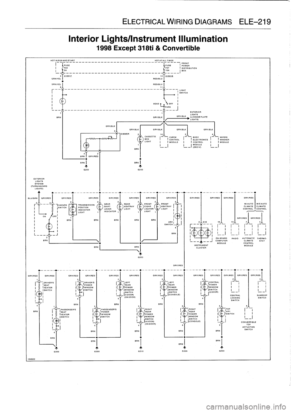
Interior
Lights/Instrument
Illumination
1998Except
318ti
&
Convertible
HOTINRUNANDSTART
HOTATALLTIMES
FRONT
I
FUSE
FUSE
f
POWER
I
122
137
I
DISTRIBUTION
I
5A
10A
BOX
-
-
-
-
-
-
-
--
-
-
-
-
-
-
-
-
-
------
-
-
-
-
-
-
-
-
-
-
aT
X19012
14~7
''
XUQQjA
GR
./V.1'
RED/BLU
I
GRNIVEL~
RED/11-
I
8
11
LIGHT
SWITCH
I
I
I
I
HEAD
I
_
.11
-
-
-
-
-
_
_
_
_
_
_
_
_
-
_
_
_
_
_
_
_
_
_
_
_
_
_
_
_
4
.
-
-
7
1
Y
EXTERIOR
LIGHTS
SAN
GRVIBLK
~GRVIBLK
(LICENSEPLATE
I
I/
'
LIGHTS)
BLUIGRN
I
GRYIRED
(
GRYIRED
(
GRY/RED
(
GRYIRED
(
GRYIRED
(
GRVIRED
(
GRY/RED
(
I
GRVIRED
(
GRVIRED
(
GRVIRED
(
GFWRED
IN/
AUTO
W/
.AUTO
CLIMATECLIMATE
CONTROL
CONTROL
1Y
BRN
I
GRY/BL3I
GRV/BLK
GRVIBLK
I
GRV/BLK
GRVIBLK
++l///ll
.
DIMMER
2
f
1q
2
4q
CASSETTE
CHECK
BODY
WIPER/
BOX
I
(
CONTROL
I
I
ELECTRONICS
I
I
WgSHER
LIGHT
I
(
MODULE
I
(
CONTROL
I
(
MODULE
1
YYT///
I_I
I_I
(ZKE
I
IV)
I
_I
BR
N
/
N~
GRVIRED
I
BR
BRN
I
BRN
1
2
G2D2
G203
TRANSMISSION
POSITION
INDICATOR
LIGHT
SAN
ELECTRICAL
WIRING
DIAGRAMS
ELE-219
GEAR
2,1,
_REAR
2~
.
FRONT
2
~
FRONT2~
.
SHIFT
ASHTRAY
CIGAR
~gSHTRAY
I
~
I
LEVER
LIGHT
INDICATOR
1
y
'
1T
LIGHT
1y
1
I
I
BAN
BAN
SAN
BAN
I
ABCSWITCHSWITCH
-
a
.AN
GRYIRED
GRYIRED
(
GRYIRED
I
GRYIRED
(
GRYIRED
(
GRV/RED
(
GRV/RED
(
GRYIRED
(
GRV/RED
(
GRYIRED
(
GAY/RED
(
GRV/PEO
I
GRYIRED
(
GRV/RED
DRIVER'S
LEFT
LEFT
CENTRAL
(POWER
I(
REAR
I
(
REAR
I
(POWER
I
I
II
(WINDOW
(POWER
IpOWER
(WINDOW
I
I
I
I
~IswIrcH
IWINDOW
t
Iwlrvoow
ISWITCH
II
II
I
II
I
-
-
SWITCH
S
W
ITCH
(2
DOOR)DOOR)
((CONSOLE)
I
_I
CENTRAL
SUNROOF
ON
DOOR)
~Y
eY
LOCKING
SWITCH
SWITCH
PASSENGER'S
p
,
~
RIGHT
RIGHT
~TOP
POWER
i/'J`\
(
REAR
REAR
i/T\'HIFI
I
-I
(WINDOWOWER
OWER
I/\~~~~//(SWITCH
II
IswIrCH
I
IWINDOW
I
IwINOOw
I
I
I
_
_I
_
-
I(
DIOOR)
ISW
TCH(CD
I
NSOLE)
I
CONVERTIBLE
Y
Y
(DNDOOR)
'Y
lY
TOP
I
BI
ACTUATING
BRN
RN
SAN
I
SWITCH
%1B
1B
13I
GRYIRED
GRV/RED
I
I
I
I
I
I
I
I
I
I
f
1
I
I
I
I
I
I
I
f
-
I
I
_~
I
_I
I
_I
II
~
j
ON-BOARD
RADIO
AUTOMATIC
THERMO-
-
COMPUTER
CLIMATE
STAT
MODULE
CONTROL
INSTRUMENT
MODULE
CLUSTER
I
I
RAN
1
I
1
1
1
1
G300
G310
G300
G203
Page 716 of 759
HO7A7AlL71ME5
HOTATALLTIMES
r
--
68544
i
*---AAA
POWER
AUTOMATIC
CUTOUT
O
PASSENGER'S
WINDOWMOTOR
V
1
G3D2
B
r
COMFDRT~
VIOIYEL
(IRELAY
I
ELECTRICAL
WIRING
DIAGRAMS
ELE-233
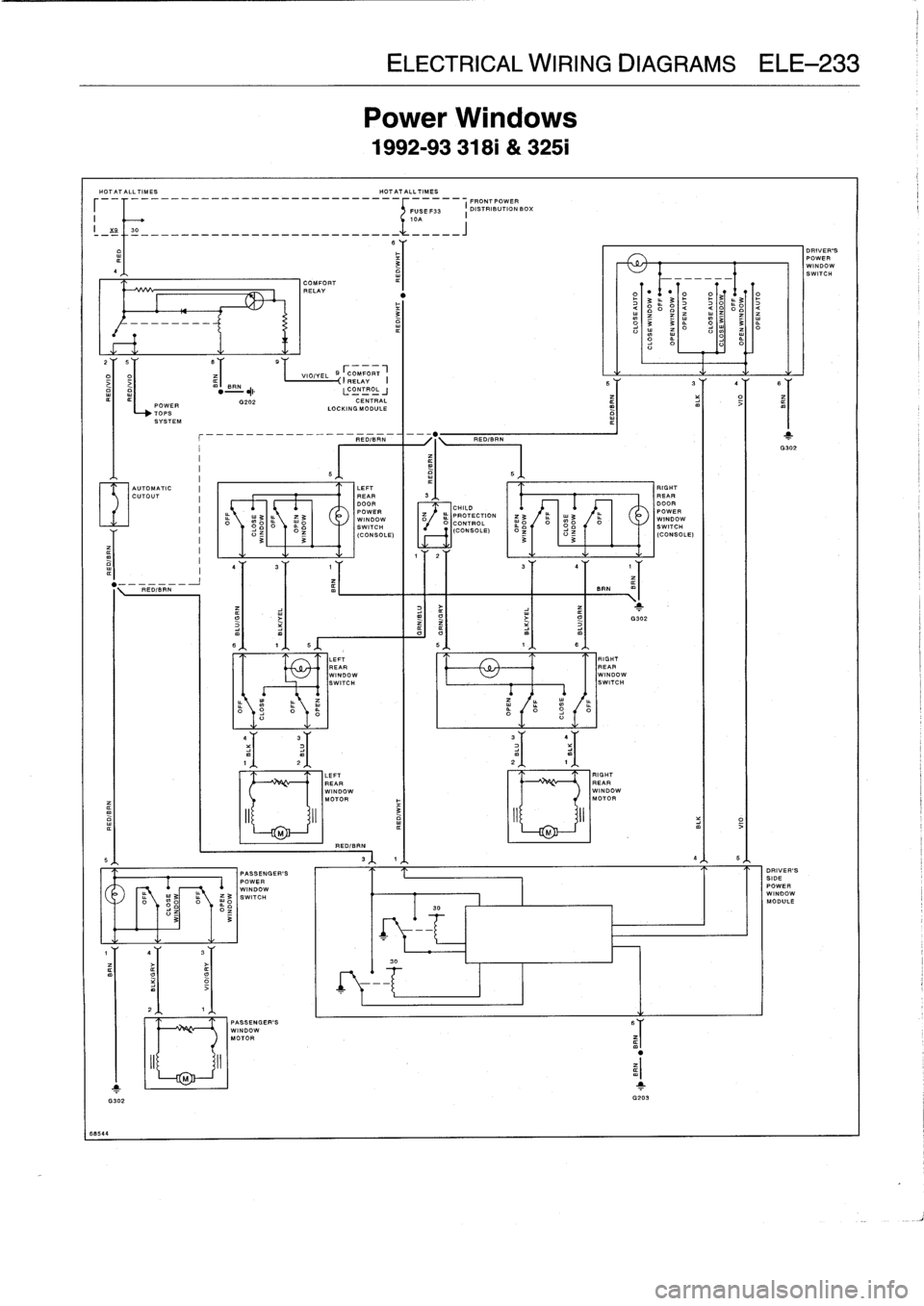
Power
Windows
1992-93
318i
&
325i
COMFORT
RELAY
mI
gANCONTROL
G202
CENTRAL
LOCKING
MODULE
I--1TOPS
SYSTEM
REDIBRN
%
\
REDIBRN
I
G302
REDIBIBIRN
R
m
PASSENGER'S
POWER
WINDOW
w3
SWITCH
03
5
LEFT
RIGHT
REAR
3
REARDOOR
1
DOOR
CHILD
POWER
PROTECTION
POWER
WINDOW
w
;op
Ho
p
WINDOWCONTROL
SWITCH
OO
O
(CONSOLE)
SWITCH
(CONSOLE)
33
(CONSOLE)
,T
2
LEFTREAR
WINDOW
SWITCH
LEFT
REAR
WINDOWMOTOR
REDIBRN
I
FRONTPOWER
FUSE
F33
I
DISTRIBUTION
BOX
BAN
RIGHT
REAR
WINDOW
SWITCH
RIGHT
REAR
WINDOW
MOTOR
M
1
G302
O
O
r
DRIVER'S
SIDE
POWER
WINDOW
MODULE
DRIVER'S
POWERWINDOW
SWITCH
Page 750 of 759
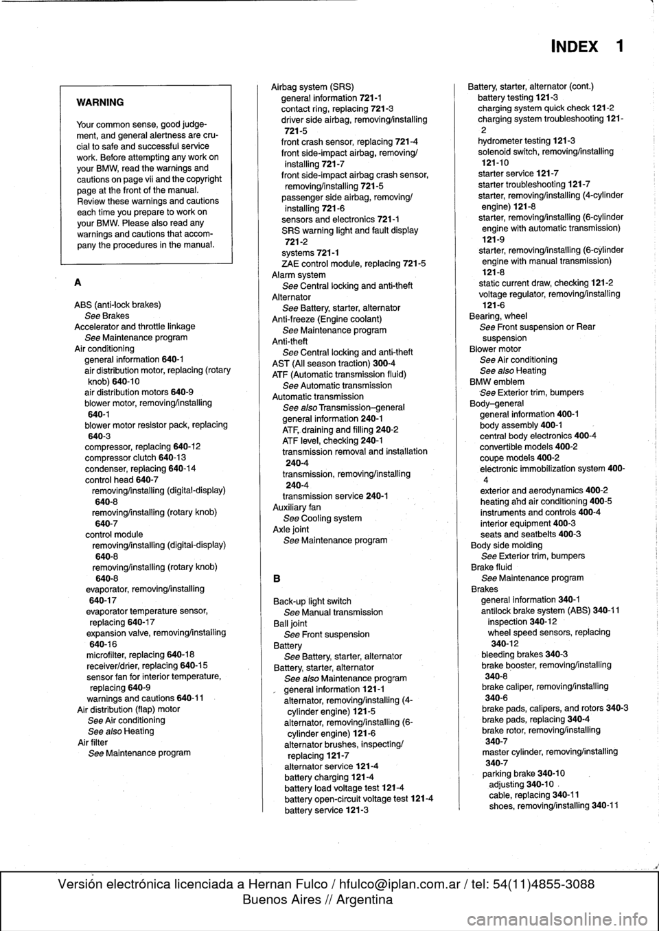
WARNING
Your
common
sense,
good
judge-
ment,
and
general
alertness
are
cru-
cial
to
safe
and
successful
service
work
.
Before
attempting
any
work
on
your
BMW,
read
the
warnings
and
cautions
on
page
vi¡
and
the
copyright
page
at
the
front
of
the
manual
.
Review
these
warnings
and
cautions
each
time
youprepare
to
work
on
your
BMW
.
Please
also
read
any
warnings
and
cautions
that
accom-
pany
the
procedures
in
the
manual
.
A
ABS
(anti-lock
brakes)
See
Brakes
Accelerator
and
throttle
linkage
See
Maintenance
program
Air
conditioning
general
information
640-1
air
distribution
motor,
replacing
(rotary
knob)
640-10
air
distribution
motors
640-9
blower
motor,
removing/installing
640-1blower
motor
resistor
pack,
replacing
640-3
compressor,
replacing
640-12
compressor
clutch
640-13
condenser,
replacing
640-14
control
head
640-7
removing/installing
(digital
-display)
640-8
removing/installing
(rotary
knob)
640-7
control
module
removing/installing
(digital-display)
640-8
removing/installing
(rotary
knob)
640-8
evaporator,
removinglinstalling
640-17
evaporator
temperature
sensor,
replacing
640-17
expansion
valve,
removing/installing
640-16
microfilter,
replacing
640-18
receiverldrier,
replacing
640-15
sensor
fan
forinterior
temperature,
replacing
640-9
warnings
and
cautions
640-11
Air
distribution
(flap)
motor
See
Air
conditioning
See
also
Heating
Air
filter
See
Maintenanceprogram
Airbag
system
(SRS)
general
information
721-1
contact
ring,
replacing
721-3
driver
side
airbag,removing/installing
721-5
front
crash
sensor,
replacing
721-4
front
side-impact
airbag,
removing/
installing
721-7
front
side-impact
airbag
crash
sensor,
removing/installing
721-5
passenger
side
airbag,
removing/
installing
721-6
sensors
and
electronics
721-1
SRS
warning
light
and
fault
display
721-2
systems
721-1
ZAE
control
module,
replacing
721-5
Alarm
system
See
Central
locking
and
anti-theft
Alternator
See
Battery,
starter,
alternator
Anti-freeze
(Engine
coolant)
See
Maintenance
program
Anti-theft
See
Central
lockíng
and
anti-theft
AST
(Al¡
season
traction)
300-4
ATF
(Automatic
transmission
fluid)
See
Automatic
transmission
Automatic
transmission
See
alsoTransmission-general
general
information
240-1
ATF,draining
and
filling
240-2
ATF
leve¡,
checking
240-1
transmission
removaland
ínstallation
240-4
transmission,
removinglinstalling
240-4
transmission
service
240-1
Auxiliary
fan
See
Cooling
system
Axle
joint
See
Maintenance
program
B
Back-up
light
switch
See
Manual
transmission
Balljoint
See
Front
suspension
Battery
See
Battery,
starter,
alternator
Battery,
starter,
alternator
See
also
Maintenance
program
general
information
121-1
alternator,
removing/installing
(4-
cylinder
engine)
121-5
alternator,
removinglinstalling
(6-
cylinder
engine)
121-6
alternator
brushes,
inspecting/
replacing
121-7
alternator
service
121-4
batterycharging
121-4
battery
load
voltage
test
121-4
batteryopen-circuit
voltage
test
121-4
battery
service
121-3
INDEX
1
Battery,
starter,
alternator
(cont
.)
battery
testing
121-3
charging
system
quick
check121-2
charging
system
troubleshooting
121-
2
hydrometer
testing
121-3
solenoid
switch,
removinglinstalling
121-10
starter
service
121-7
starter
troubleshooting
121-7
starter,
removing/installing(4-cylinder
engine)
121-8
starter,
removing/installing(6-cylinder
engine
with
automatic
transmission)
121-9
starter,
removing/installing
(6-cylinder
engine
with
manual
transmission)
121-8
static
current
draw,
checking
121-2
voltage
regulator,
removing/installing
121-6
Bearing,
wheel
See
Front
suspension
or
Rear
suspension
Blowermotor
See
Air
conditioning
See
also
Heatíng
BMW
emblem
See
Exterior
trim,
bumpers
Body-general
general
information
400-1
body
assembly
400-1
central
body
electronics
400-4
convertible
models
400-2
coupe
models
400-2
electronic
immobilizatíon
system
400-
4
exterior
and
aerodynamics
400-2
heating
afhdair
conditioning
400-5
instruments
and
controls
400-4
interior
equipment
400-3
seats
and
seatbelts
400-3
Body
side
molding
See
Exterior
trim,
bumpers
Brake
fluid
See
Maintenance
program
Brakes
general
information
340-1
antilock
brake
system
(ABS)
340-11
inspection
340-12
wheelspeed
sensors,
replacing
340-12
bleeding
brakes
340-3
brake
booster,
removinglinstalling
340-8
brake
caliper,
removing/installing
340-6
brake
pads,
calipers,
and
rotors
340-3
brake
pads,
replacing
340-4
brake
rotor,
removing/installing
340-7
master
cylinder,
removing/installing
340-7
parking
brake
340-10
adjusting
340-10
.
cable,
replacing
340-11
shoes,
removinglinstalling
340-11
Page 754 of 759
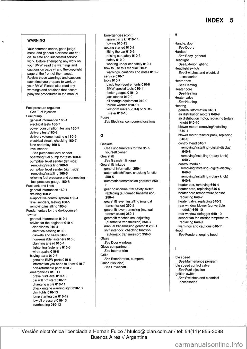
WARNING
Your
common
sense,
good
judge-
ment,
and
general
alertness
are
cru-
cial
tosafe
and
successful
service
work
.
Before
attempting
any
work
on
your
BMW,
read
the
warnings
and
cautions
on
page
vi¡
and
the
copyright
page
at
the
frontof
the
manual
.
Review
these
warnings
and
cautions
each
time
you
prepare
to
work
on
your
BMW
.
Please
also
read
any
warnings
and
cautions
that
accom-
pany
the
procedures
in
the
manual
.
Fuel
pressure
regulator
See
Fuel
injection
Fue]
pump
general
information
160-1
electrical
tests
160-7
power
consumption,
testing
160-7
delivery
tests160-8
delivery
volume,
testing
g
160-9
electrical
circuit,
checking
160-7
fuse
and
relay
160-6
level
sender
See
pump/fuel
leve¡
sender
operating
fuel
pump
for
tests
160-6
pump/fuel
level
sender
(left
side),
removing/installing
160-6
pump/fuel
leve¡
sender
(right
side),
removing/installing
160-5
relieving
fuel
pressure
and
connecting
fue¡
pressure
gauge
160-8
Fueltank
and
lines
general
information
160-1
draining
160-2
evaporative
control
system
160-4
leve¡
senders,
testing
160-5
removing/installing
160-3
Fundamentals
for
the
do-it-yourself
owner
general
information
010-1
advice
for
the
beginner
010-4
cleanliness
010-4
electrical
testing
010-6
gaskets
and
seals
010-5
non-reusable
fasteners
010-5
planning
ahead
010-4
tightening
fasteners
010-5
wire
repairs
010-6
buying
parts
010-6
genuine
BMW
parts
010-6
information
you
need
to
know
010-7
non-returnable
parts
010-7
emergencies
010-11brake
fluid
leve¡
010-13
car
will
not
start
010-11
changinga
tire
010-11
check
enginewarning
light
010-13
dim
Iights
010-13
jump
starting
car
010-12
low
o]I
pressure
010-13
overheating
010-12
Emergencies
(cont
.)
spare
parts
kit
010-14
towing
010-13
gettingstarted
010-2
lifting
thecar
010-3
raising
car
safely
010-3
safety
010-2
working
under
car
safely
010-4
how
to
use
this
manual
010-2
warnings,
cautions
and
notes
010-2
service
010-7
tools
010-7
basic
tool
requirements010-8
BMW
specialtools
010-11
feeler
gauges
010-10
jack
stands
010-9
oil
change
equipment
010-9
torque
wrench
010-10
volt-ohm
meter
(VOM)
or
Multi-
meter010-10
Fuses
See
Electrical
component
locations
G
Gaskets
See
Fundamentals
for
the
do-it-
yourself
owner
Gearshift
See
Gearshift
linkage
Gearshift
linkagegeneral
information
250-1
automatic
shiftlock,
checking
function
250-5
automatic
transmission
gearshift
250-
3
gear
position/neutral
safety
switch,
replacing
(automatic
transmission)
250-4
gearshift
lever,
installing
(manual
transmission)
250-2
gearshift
lever,
removing
(manual
transmission)
250-1
gearshift
mechanism,
adjusting
(automatictransmission)
250-3
manual
transmission
gearshift
250-1
shift
interlock,
checking
function
(automatic
transmission)
250-6Glass
See
Door
windows
Glove
compartment
See
Interior
trim
Grille
See
Exterior
trim,
bumpers
Guibo
(flex
disc)
See
Driveshaft
Handle,
door
See
Doors
Hardtop
See
Body-general
Headlight
See
Exterior
lighting
Headlight
switch
See
Switches
and
electrical
accessoriesHeater
box
See
Heating
Heater
core
See
Heating
Heater
valve
See
Heating
Heating
general
information
640-1
air
distribution
motors
640-9
air
distribution
motor,
replacing
(rotary
knob)
640-10
blower
motor,
removing/installing
640-1blower
motor
resistor
pack,
replacing
640-3
control
head
640-7
removing/installing
(digital-display)
640-8
removing/installing
(rotary
knob)
640-7
control
module
removing/installing
(digital-display)
640-8
removing/installing
(rotary
knob)
640-8
heater
box,
removing640-4
heater
core,
replacing
640-6
heater
core
temperature
sensor,
replacing
640-7
heater
valve,
replacing
640-3
rear
window
blower
(convertible
models)
640-10
reas
window
defogger
640-10sensor
fan
forinterior
temperature,
replacing
640-9warnings
and
cautions
640-11
Hood
See
Fenders,
engine
hood
Idle
speed
See
Maintenance
program
Idle
speed
control
valve
See
Fuel
injection
Ignition
switch
See
Switches
and
electrical
accessories
INDEX
5