warning light BMW M3 1998 E36 Owner's Manual
[x] Cancel search | Manufacturer: BMW, Model Year: 1998, Model line: M3, Model: BMW M3 1998 E36Pages: 759
Page 127 of 759
IGNITION
SYSTEM
DIAGNOSTICS
IGNITION
SYSTEM
SERVICE
Poor
driveability
may
have
a
variety
of
causes
.
The
fault
On
4-cylinder
engines,
an
ignition
coil
pack
is
mounted
to
may
lie
with
the
ignition
system,
the
fuel
system,
parts
of
the
the
passenger
side
strut
tower
in
the
engine
compartment
.
emission
control
system,
or
a
combination
of
the
three
.
Be-
The
coil
pack
integrates
4
individual
coils
.
cause
of
these
interrelated
functions
and
their
effects
oneach
other,
it
is
often
difficult
to
know
where
to
begin
looking
for
On
6-cylinder
engines,
an
ignition
coil
is
located
directly
problems
.
above
each
spark
plug
.
For
this
reason,
effective
troubleshooting
should
alwaysbe-
gin
with
an
interrogation
of
the
On-Board
Diagnostic
(OBD)
system
.
The
OBD
system
detects
certain
emissions-related
engine
management
malfunctions
.
When
faults
are
detected,
the
OBD
system
stores
a
Diagnostic
Trouble
Code
(DTC)
in
the
system
ECM
.
In
addition,
the
Check
Enginewarning
light
will
come
on
if
an
emissions-related
fault
is
detected
.
Two
generations
of
OBD
areusedon
the
cars
coveredby
this
manual
.
See
100
Engine-General
for
OBD
information
.
On-Board
Diagnostics
"
1992-1995
models
............
...
.
..
...
OBD
I
"
1996
and
later
models
.........
.......
..
OBD
II
NOTE-
"
On
carswith
OBD
ti,
specialized
OBD
11
scan
tool
equipment
mustbeused
to
access
DTCs,
either
using
the
BMW
special
tool
or
a
`generic"
OBD
11
scan
tool
.
"
The
OBD
11
fault
memory
(including
an
illuminated
Check
Engine
light)
can
only
be
reset
using
the
spe-
cial
scan
tool
.
Removing
the
connector
from
the
ECM
or
dísconnecting
the
battery
will
not
erase
the
fault
memory
.
Basic
Troubleshooting
Principies
An
engine
that
starts
and
runs
indicates
the
ignition
system
is
fundamentally
working-delivering
voltage
toat
least
some
of
the
sparkplugs
.
A
hard-starting
or
poor-running
engine,
however,
may
indicate
ignition
coil
problems,
cracked
or
dete-
riorated
spark
plug
wires
(4-cylinder
engines
only),
and
worn
or
fouled
spark
plugs
.
WARNING
-
Inefficient
combustion
(richair/fuel
mixture)
can
cause
the
catalytic
converter
to
overheat
and
plug
.
An
overheated
catalytic
converter
can
also
bea
tire
hazard
.
Checking
for
Spark
IGNITION
SYSTEM
120-
3
WARNING
-
If
a
spark
test
is
done
incorrectly,
damage
to
theen-
gine
control
module
(ECM)
or
the
ignitioncoil(s)
may
result
.
Checking
for
spark
is
difficult
onengines
with
distributorless
ignition
systems
.
Try
Rmovng
the
plugs
and
inspecting
for
differences
be-
tween
them
.
A
poor-firing
plug
may
be
wet
with
fuel
and/or
black
and
sooty,
butnot
always
.
If
a
coil
is
not
operating,
the
engine
management
system
will
electrically
disable
the
fuel
injectorto
that
cylinder
.
The
key
is
to
look
for
differences
be-
tween
cylinders
.
Ignition
coil,
testing
and
replacing
(4-cylinder
engine)
1.
Disconnect
mainharness
connector
from
coils
:
"
On
M42
engine,
remove
plastic
covering
from
coils
and
disconnect
individual
harness
connectors
.
"
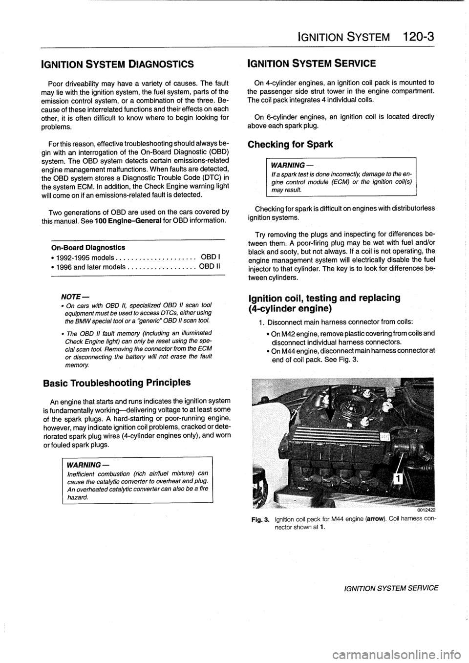
On
M44
engine,
disconnect
main
harness
connectorat
end
of
coil
pack
.
See
Fig
.
3
.
Fig
.
3
.
Ignition
coil
pack
for
M44
engine
(arrow)
.
Coil
harness
con-
nector
shown
at1
.
IGNITION
SYSTEM
SERVICE
Page 140 of 759
121-
4
BATTERY,
STARTER,
ALTERNATOR
BatteryOpen-Circuit
Voltage
Test
Battery
Charging
Before
making
the
test,
load
the
battery
with
15
amperes
for
Discharged
batteries
can
be
recharged
using
a
battery
one
minute
with
a
batteryload-tester
or
turn
on
the
headlights
charger
.
The
battery
should
be
removed
from
the
luggage
for
about
one
minute
without
the
engine
running
.Then
discon-
compartment
during
charging
.
nect
the
battery
negative
(-)
cable
and
connect
a
digital
volt-
meter
acrossthe
battery
terminals
.
Open-circuit
voltage
Prolonged
charging
causes
electrolyte
evaporation
to
a
lev
levels
are
given
in
Table
c
.
el
that
can
damage
the
battery
.
Itis
bestto
use
a
low-current
charger
(6
amperes
or
less)
to
prevent
battery
damage
If
the
open-circuit
voltage
ís
OK
butthe
battery
still
lacks
caused
by
overheating
.
power
for
starting,
make
a
load
voltage
test
.
If
the
open-circuit
voltage
is
below
12
.4
volts,
recharge
the
battery
and
retest
.
WARNING
-
Hydrogen
gas
given
off
by
the
battery
duringcharg-
Table
c
.
Open-Circuit
Voltage
and
Battery
Charge
ing
is
explosive
.
Do
not
smoke
.
Keep
open
llames
away
from
the
top
of
the
battery,
and
prevent
elec
Open-circuit
voltage
State
of
charge
trical
sparks
by
turning
offthe
battery
charger
be-
12
.6
V
or
more
Fully
charged
fore
connecting
or
disconnecting
it
.
12
.4
V
1
75%
charged
12
.2
V
50%
charged
CAUTION-
12
.0
V
25%
charged
"
Battery
electrolyte
(sulfuric
acid)
can
damage
the
car
.
If
electrolyte
isspilled,
clean
the
area
11
.7
V
or
less
Fully
discharged
with
a
solution
of
baking
soda
and
water
.
Battery
Load
Voltage
Test
A
battery
load
tester
is
required
for
a
load
voltage
test
.
The
-
Always
disconnect
both
battery
cables
and
re-
test
is
made
by
applying
a
high
resistive
load
to
the
battery
ter-
move
battery
from
vehicle
during
battery
charg-
ing
.
Do
not
exceed
16
.5volts
at
the
battery
.
minals
and
then
measuring
battery
voltage
.
The
battery
should
be
fully
charged
for
the
most
accurate
results
.
The
battery
ca-
bles
mustbe
disconnected
before
making
the
test
.
If
the
volt-
ALTERNATOR
$ERVICE
age
is
below
that
listed
in
Table
d,
the
battery
should
be
replaced
.
WARNING
-
Always
wear
protective
goggles
and
clothing
when
performing
aload
test
.
Table
d
.
Battery
Load
Test-Minimum
Voltage
(apply
200
amp
load
for
15
seconds)
Ambient
temperature
Voltage
80°F
(27°C)
9
.6
V
60°F
(16°C)
9
.5
V
40°F
(4°C)
9
.3
V
20°F
(-7°C)
8
.9
V
0°F
(-18°C)
8
.5
V
ALTERNATOR
SERVICE
"
Always
allow
a
frozen
battery
to
thaw
before
at-
tempting
to
recharge
it
.
Before
checking
the
alternator
and
regulator,
make
sure
the
battery
is
fully
charged
and
capable
of
holding
acharge
.
Check
that
the
battery
terminals
are
clean
and
tight
and
the
al-
ternator
drive
belt
is
properly
tensioned
and
not
severely
worn
.
Charging
system,
checking
CAUTION-
Do
not
disconnect
the
battery
while
the
engine
is
running,
.
Damage
to
the
alternator
andlorengine
electronic
systems
may
result
.
1.
Turn
ignition
key
on
.
Check
that
the
chargewarning
lamp
comes
on
.
NOTE-
If
the
warning
light
does
not
come
on,
repair
any
wiring
or
bulb
faults
before
continuing
to
check
the
charging
system
.
Page 141 of 759
2
.
Remove
cooling
duct
or
terminal
cover
from
rear
of
al-
2
.
Remove
air
cleaner
upper
section
with
mass
air
flow
ternator
.
sensor
.
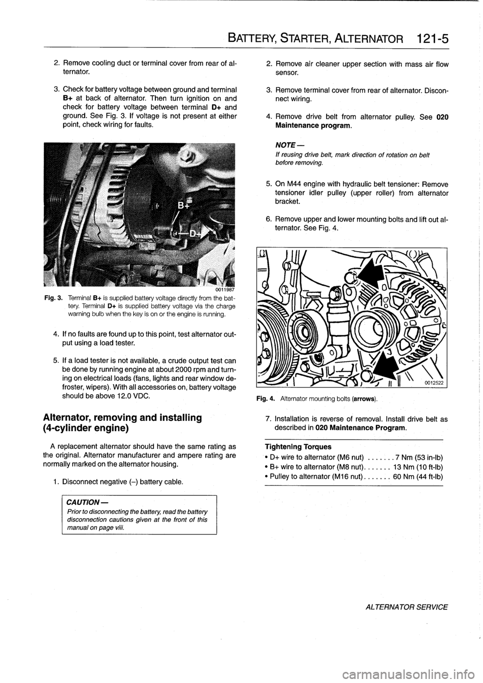
3
.
Check
for
battery
voltage
between
ground
and
terminal
3
.
Remove
terminal
cover
from
rear
of
alternator
.
Discon
B+
at
back
of
alternator
.
Then
turn
ignition
on
and
nect
wiring
.
check
for
battery
voltage
between
terminal
D+
and
ground
.
See
Fig
.
3
.
lf
voltage
is
not
present
at
either
4
.
Remove
drive
belt
from
alternator
pulley
.
See
020
point,
check
wiring
for
faults
.
Maintenance
program
.
001
¡987
Fig
.
3
.
Terminal
B+
is
supplied
battery
voltage
directly
from
the
bat-
tery
.
Terminal
D+
is
supplied
battery
voltage
via
the
charge
warning
bulb
when
thekey
is
on
or
the
engine
is
running
.
4
.
lf
no
faults
are
foundup
to
thispoint,test
alternator
out-
put
using
a
load
tester
.
5
.
If
a
load
tester
is
not
available,
a
crude
output
test
can
be
done
by
running
engine
at
about
2000
rpmand
turn-
ing
on
electrical
loads
(fans,
lights
and
rear
window
de-
froster,
wipers)
.
With
al¡
accessories
on,
battery
voltage
should
be
above
12
.0
VDC
.
A
replacement
alternator
should
have
the
same
rating
as
the
original
.
Alternator
manufacturer
and
ampere
rating
are
normally
marked
on
the
alternator
housing
.
1
.
Disconnect
negative
(-)
battery
cable
.
CAUTION-
Prior
to
disconnecting
the
battery,
read
the
battery
disconnection
cautions
given
at
the
front
of
this
manual
on
page
vi¡¡
.
BATTERY,
STARTER,
ALTERNATOR
121-
5
6
.
Remove
upper
and
lower
mounting
bolts
and
lift
out
al-
ternator
.
See
Fig
.
4
.
NOTE
-
If
reusing
drive
belt,
mark
direction
of
rotation
on
belt
before
removing
.
5
.
On
M44
engine
with
hydraulic
belt
tensioner
:
Remove
tensioner
idler
pulley
(upper
roller)
from
alternator
bracket
.
Fig
.
4
.
Alternator
mounting
bolts
(arrows)
.
O
u
J
S
v~~
U
I
1
i
n
-12
.22
Alternator,
removing
and
installing
7
.
Installation
is
reverse
of
removal
.
Install
drive
belt
as
(4-cylinder
engine)
described
in
020
Maintenance
Program
.
Tightening
Torques
"
D+
vire
to
alternator
(M6
nut)
.
...
.
.
.
7
Nm
(53
in-lb)
"
B+
wire
to
alternator
(M8
nut)
..
.
.
.
.
.
13
Nm
(10
ft-Ib)
"
Pulley
to
alternator
(M16
nut)
...
..
..
60
Nm
(44
ft-Ib)
ALTERNATOR
SERVICE
Page 144 of 759
121-
8
BATTERY,
STARTER,
ALTERNATOR
1f
the
solenoid
audibly
cliicks
but
the
motor
does
not
turn,
Starter,
removing
and
installing
switch
on
the
lights
andtum
the
key
to
the
start
position
.
lf
the
(6-cylinder
engine
with
lights
go
out
while
attempting
to
start,
the
battery
cable
may
be
manual
transmission)
loose
or
the
starter
may
have
a
short
circuit
.
If
the
lights
stay
on,the
solenoid
is
most
likely
atfault
.
The
starter
on
a
6-cylinder
car
with
manual
transmission
is
Starter,
removing
and
installing
(4-cylinder
engine)
1
.
Disconnect
negative
(-)
battery
cable
.
1
.
Disconnect
negative
(-)
cable
from
battery
.
CAUTION-
Prior
to
disconnecting
the
battery,
read
the
battery
disconnection
cautions
given
at
the
front
of
this
manual
on
page
viii
.
2
.
Remove
guide
tube
for
oil
dipstick
.
3
.
Raise
vehicle
.
WARNING
-
Make
sure
the
car
ís
stable
and
wefl
supported
at
all
times
.
Use
a
professional
automotive
lift
or
jack
stands
designed
forthe
purpose
.
A
floor
jack
is
not
adequate
support
.
4
.
Disconnect
wiring
from
starter
.
5
.
Remove
top
and
bottom
starter
bolts
.
Bottom
bolt
must
be
removed
from
below
car
.
Remove
starter
support
bracket,
if
applicable
.
removed
from
below
.
2
.
Raise
vehicle
.
3
.
Remove
reinforcing
cross
bracefromunder
transmís-
sion,
if
applicable
.
4
.
Remove
cover
from
fuel
filter
and
fuel
lines
on
left
side
underneath
car,
if
applicable
.
Detach
fuel
lines
and
har-
ness
connectors
from
retainingbrackets,
as
necessary
5
.
Disconnect
wiring
from
starter
.
6
.
Loosen
andremove
bolts
and
nuts
fastening
starter
to
transmission
bell
housing
and/or
engine
block
.
Remove
starter
supportbracket
.
7
.
Remove
starter
from
below
.
8
.
Check
starter
pinion
gear
and
flywheel
teeth
for
dam-
age
.
9
.
Installation
is
reverse
of
removal
.
6
.
Pull
starter
downward
and
turn
until
solenoid
is
at
top,
Tightening
Torques
then
remove
from
car
.
"
Re¡
nforcing
cross
brace
to
chassis
(M10)
..
...............
42
Nm
(31
ft-Ib)
7
.
>Check
starter
pinion
gear
and
flywheel
teeth
for
dam-
"
Starter
to
engine
block
(M10
bolt)
...
50
Nm
(37
ft-Ib)
age
.
"
Support
bracket
to
starter
(M5
nut)
...
5
Nm
(44
in-lb)
"
Support
bracket
8
.
Installation
is
reverse
of
removal
.
to
engine
block
(M10
bolt)
.........
47
Nm
(35
ft-Ib)
"
Wire
to
terminal
50
(M6
nut)
.........
6
Nm
(53
ín-Ib)
"
Wire
to
terminal
30
(M8
nut)
.........
12
Nm
(9
ft-lb)
Tightening
Torques
"
Starter
to
engine
block
(M10
bolt)
...
50
Nm
(37
ft-lb)
Wire
to
terminal
50
(M6
nut)
........
6
Nm
(53
in-lb)
"
Wire
toterminal
30
(M8
nut)
...
,
..:.
12
Nm
(9
ft-Ib)
STARTER
SERVICE
Page 150 of 759
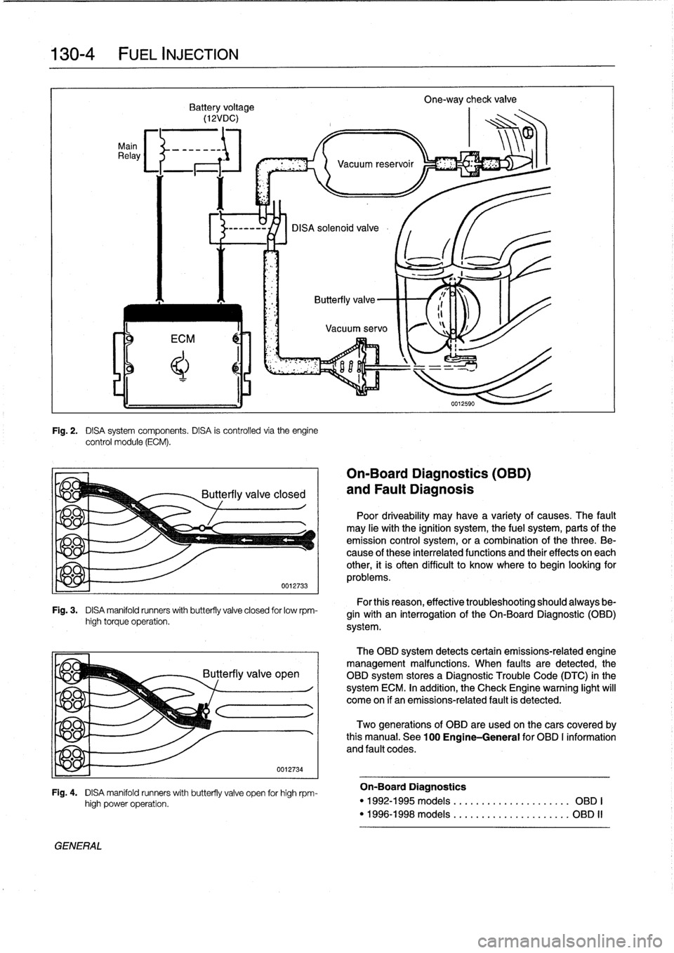
130-
4
FUEL
INJECTION
Main
Relay
Fig
.
2
.
DISA
system
components
.
DISA
is
controlled
via
theengine
control
module
(ECM)
.
Fig
.
3
.
DISA
manifold
runners
with
butterfly
valve
closed
for
lowrpm-
high
torque
operation
.
yje
q
GENERAL
high
power
operation
.
0012734
Fig
.
4
.
DISA
manifold
runners
with
butterfly
valve
open
for
high
rpm-
On-Board
Diagnostics
(OBD)
and
Fault
Diagnosis
Poor
driveability
may
have
a
variety
of
causes
.
The
fault
may
He
withthe
ignition
system,
the
fuel
system,
parts
ofthe
emission
control
system,
ora
combination
of
thethree
.
Be-
cause
of
these
interrelated
functions
and
their
effects
on
each
other,
it
is
often
difficult
to
know
where
to
begin
looking
for
problems
.
For
this
reason,
effective
troubleshooting
should
always
be-
gin
with
an
interrogation
of
the
On-Board
Diagnostic
(01313)
system
.
The
OBD
system
detects
certain
emissions-related
engine
management
malfunctions
.
When
faults
are
detected,the
OBD
system
storesa
Diagnostic
Trouble
Code
(DTC)
in
the
system
ECM
.
In
addition,
the
Check
Engine
warning
light
will
come
on
if
an
emissions-related
fault
is
detected
.
Two
generations
of
OBD
are
used
on
thecars
covered
by
this
manual
.
See
100
Engine-General
for
OBD
I
information
and
fault
codes
.
On-Board
Diagnostics
"
1992-1995models
....
.
...
...
.
...
......
OBD
I
"
1996-1998models
....
.
..
.
.
.
..
...
......
OBD
II
Page 152 of 759
130-
6
FUEL
INJECTION
Warnings
and
Cautions
For
personal
safety,
as
well
as
the
protection
of
sensitive
electronic
components,
the
following
warnings
and
cautions
should
be
adhered
to
when
working
on
the
engine
manage-
ment
system
.
GENERAL
WARNING
-
"
The
ignition
system
produces
high
voltages
that
can
be
fatal
.
Avoid
contact
with
exposed
termi-
nals
.
Use
extreme
caution
when
working
onacar
with
the
ignition
switched
on
or
the
engine
run-
ning
.
"
Do
not
touch
or
disconnect
any
high
voltage
ca-
bles
from
the
coils
or
spark
plugs
while
the
engine
is
running
or
beingcranked
by
the
starter
.
"
Connect
and
disconnect
the
DME
system
wiring
and
test
equipment
leads
only
when
the
ignition
is
switched
off
.
"
Gasoline
is
highly
flammable
and
fts
vaporsare
explosive
.
Do
not
smoke
or
work
on
a
car
near
heaters
or
other
fire
hazards
when
diagnosing
and
repalring
fuel
system
problems
.
Have
a
tire
extinguisher
avaílable
in
case
of
an
emergency
.
"
When
working
onan
open
fuel
system,
wear
suit-
able
hand
protection,
asprolonged
contact
wfth
fuel
can
cause
illnesses
and
skin
disorders
.
"
Renew
fuel
system
hoses,
clamps
and
O-rings
any
timethey
are
removed
.
"
Before
makingany
electrical
tests
that
require
the
engine
to
be
cranked
using
the
starter,
disable
the
ignition
system
as
described
in
120
Ignition
System
.
CAUTION-
"
Prior
to
disconnecting
the
battery,
read
the
bat-
tery
disconnectinn
cautions
given
at
the
front
of
this
manual
onpage
vifi
.
"
Do
not
connect
any
test
equipment
that
delivers
a
12-volt
power
supply
to
terminal
15
(+)
of
the
ig-
nitioncoil
.
The
current
flow
may
damage
the
ECM
.
In
general,
connect
test
equipment
only
as
speclfied
by
BMW,
this
manual,
or
the
equipment
maker
.
"
Only
use
a
digital
multlmeter
for
electrical
test
.
"
Only
use
an
LED
test
light
for
quick
tests
.
"
Disconnecting
the
battery
may
erase
fault
code(s)
stored
in
memory
.
Check
for
fault
codes
prior
to
disconnecting
the
battery
cables
.
ff
the
Check
Engine
light
ís
illuminated,
see100En-
gine-General
for
DME
fault
code
information
.
ff
any
other
system
faults
have
been
detected
(indi-
catedbyan
illuminated
warning
light),
see
an
au-
thorized
BMW
dealer
.
Additional
systems
with
self-diagnostic
capabilities
include,
ABS
(Anti-
lock
brakes),
SRS
(Airbags),
EML
and
ASC+T
and
AST
(Traction
Control)
.
"
Do
not
run
the
engine
wfth
any
of
the
spark
plug
wires
dlsconnected
.
Catalytic
converter
damage
may
result
.
"
Always
waitat
least
40
seconds
afterturning
off
the
ignition
before
removing
the
engine
control
module
(ECM)
connector
.
ff
the
connector
isre-
moved
before
this
time,
residual
power
in
the
sys-
tem
relay
may
damage
the
control
module
.
"
Cleanliness
is
essential
when
working
onan
open
fuel
system
.
Thoroughly
clean
fuel
line
con-
nections
and
surroundlng
areas
before
loosen-
ing
.
Avoid
moving
the
car
.
Only
fnstall
cleanparts
.
"
Fuel
system
cleaners
and
other
chemical
addi-
tives
other
than
those
specifically
recommended
by
BMW
may
damage
the
catalytic
converter,
the
oxygensensor
or
other
fuel
supply
components
.
Page 159 of 759
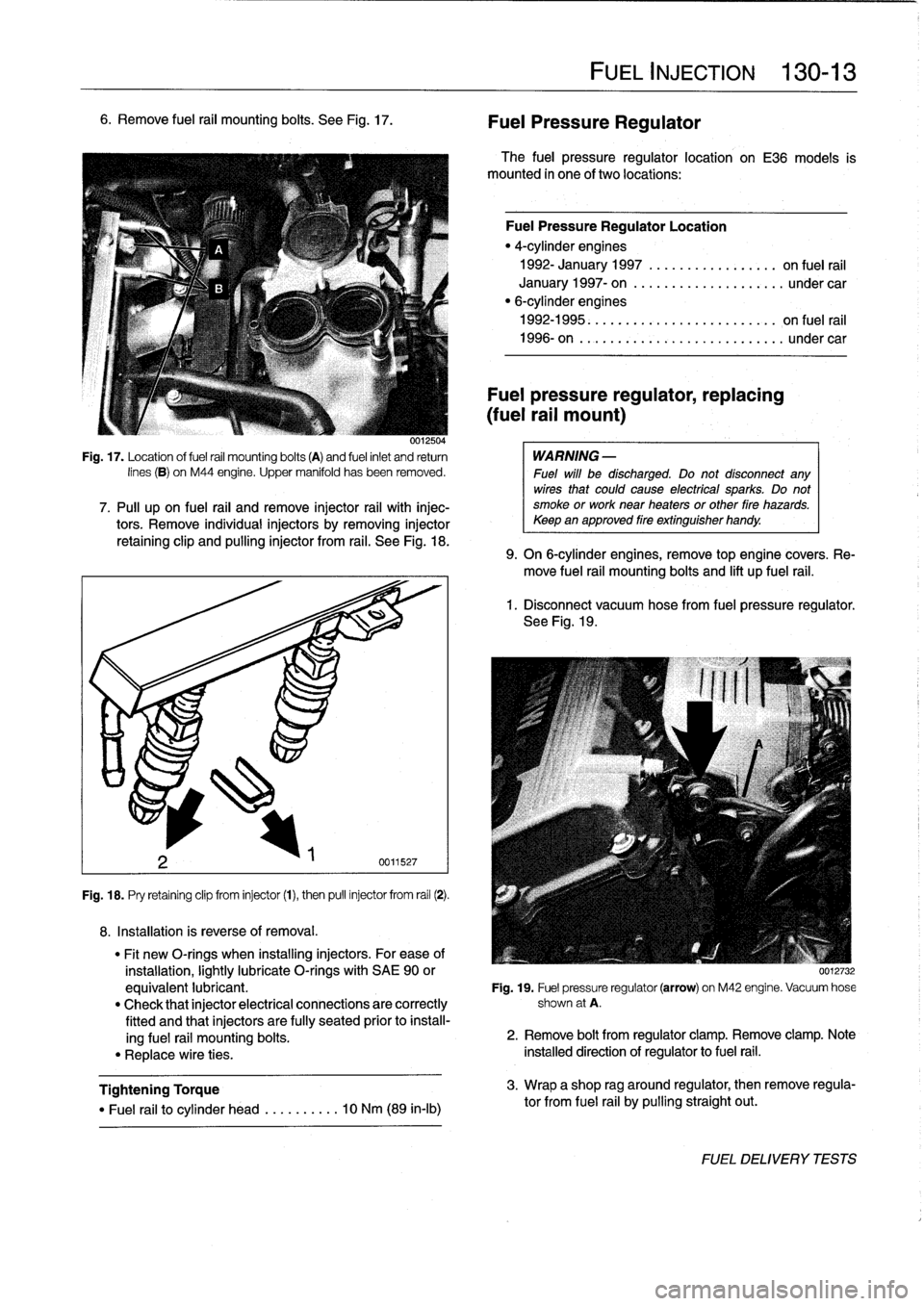
6
.
Remove
fuel
rail
mounting
bolts
.
See
Fig
.
17
.
0012504
Fig
.
17
.
Location
of
fuel
rail
mounting
bolts
(A)
and
fuel
inlet
and
return
lines
(B)
on
M44
engine
.
Upper
manifold
has
been
removed
.
7
.
Pull
upon
fuel
rail
and
remove
injector
rail
with
injec-tors
.
Remove
individualinjectors
by
removing
injector
retaining
clip
and
pullinginjector
from
rail
.
See
Fig
.
18
.
Fig
.
18
.
Pry
retaining
clip
from
injector
(1),
then
pull
injector
from
rail
(2)
.
8
.
Installation
is
reverse
of
removal
.
Tightening
Torque
"
Fuel
rail
to
cylinder
head
..
.
..
..
...
10
Nm
(89
in-lb)
FUEL
INJECTION
130-
1
3
Fuel
Pressure
Regulator
The
fuel
pressure
regulator
location
on
E36
models
is
mounted
in
one
of
two
locations
:
Fuel
Pressure
Regulator
Location
"
4-cylinder
engines
1992-
January
1997
............
...
..
on
fuel
rail
January
1997-
on
...............
..
...
under
car
"
6-cylinderengines
1992-1995
.
.
...
...
.
...........
...
..
on
fuel
rail
1996-on
..
.
..
................
...
...
undercar
Fuel
pressure
regulator,
replacing
(fuel
rail
mount)
WARNING
-
Fuel
will
be
discharged
.
Do
not
disconnect
any
wires
that
could
cause
electrícal
sparks
.
Do
not
smoke
or
work
near
heaters
or
other
fire
hazards
.
Keepan
approved
fire
extinguisher
handy
.
9
.
On
6-cylinder
engines,
remove
top
engine
covers
.
Re-
move
fuel
rail
mounting
bolts
and
lift
up
fuel
rail
.
1
.
Disconnect
vacuum
hose
from
fuel
pressure
regulator
.
See
Fig
.
19
.
"
Fit
new
O-rings
when
installing
injectors
.
For
ease
of
installation,
lightly
lubricate
O-rings
with
SAE
90
or
0012732
equivalent
lubricant
.
Fig
.
19
.
Fuel
pressure
regulator
(arrow)
on
M42
engine
.
Vacuum
hose
"
Check
that
injector
electrical
connections
are
correctly
shown
at
A
.
fitted
and
that
injectors
are
fully
seated
prior
to
install-
ing
fuel
rail
mounting
bolts
.
2
.
Remove
bolt
from
regulator
clamp
.
Remove
clamp
.
Note
"
Replace
wire
ties
.
installed
direction
of
regulator
to
fuel
rail
.
3
.
Wrap
a
shop
rag
around
regulator,
then
remove
regula-
tor
from
fuel
rail
by
pulling
straight
out
.
FUELDELIVERYTESTS
Page 169 of 759
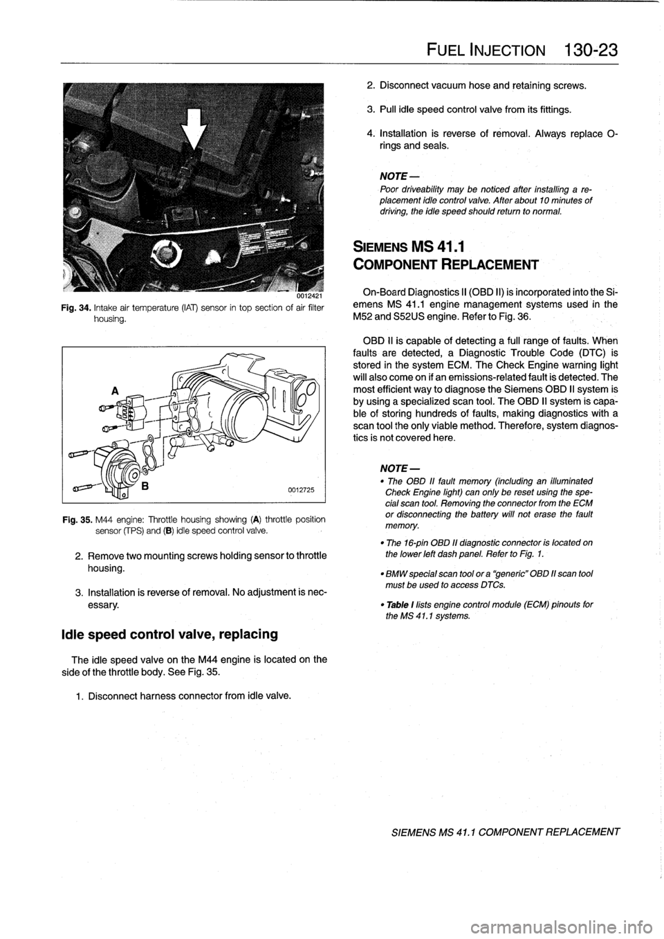
001ía4
i
Fig
.
34
.
Intake
air
temperature
(IAT)
sensor
in
top
section
of
air
filter
housing
.
¡die
speed
control
valve,
replacing
side
of
the
throttle
body
.
See
Fig
.
35
.
1
.
Disconnect
harness
connector
from
¡die
valve
.
0012725
Fig
.
35
.
M44
engine
:
Throttle
housing
showing
(A)
throttle
position
sensor
(fPS)
and
(B)
¡die
speed
control
valve
.
2
.
Remove
twomountingscrews
holding
sensor
to
throttle
housing
.
The
¡die
speed
valve
on
the
M44
engine
is
located
on
the
FUEL
INJECTION
130-23
2
.
Disconnect
vacuum
hose
and
retaining
screws
.
3
.
Pull
¡die
speed
control
valve
from
its
fittings
.
4
.
Installation
is
reverse
of
rémoval
.
Always
replace
0-
rings
and
seals
.
NOTE
Poor
driveability
may
be
notíced
after
installing
a
re-
placement
¡dio
control
valve
.
After
about10
minutes
of
driving,
the
idie
speed
should
retum
to
normal
.
SIEMENS
MS
41
.1
COMPONENT
REPLACEMENT
On-Board
Diagnostics
II
(OBD
II)
is
incorporated
into
the
Si-
emens
MS
41
.1
engine
management
systems
used
in
the
M52
and
S52US
engine
.
Refer
to
Fig
.
36
.
OBD
11
is
capable
of
detecting
a
fui¡
range
offaults
.
When
faults
are
detected,
a
Diagnostic
Trouble
Code
(DTC)
is
stored
in
the
system
ECM
.
The
Check
Engine
warning
light
will
also
come
on
if
an
emissions-related
fault
is
detected
.
The
most
efficient
way
to
diagnose
the
Siemens
OBD
II
system
is
by
using
a
specialized
scan
tool
.
The
OBD
II
system
is
capa-
ble
of
storing
hundreds
of
faults,
making
diagnostics
with
a
scan
tool
the
only
viable
method
.
Therefore,
system
diagnos-
tics
is
not
covered
here
.
NOTE
-
"
The
OBD
11
fault
memory
(including
an
illuminated
Check
Engine
light)
can
only
be
reset
using
the
spe-
cial
scan
tool
.
Removing
the
connector
from
the
ECM
or
disconnecting
the
battery
will
not
erase
the
fault
memory
.
"
The
16-pin
OBD
11
diagnostic
connector
is
located
on
the
lower
left
dash
panel
.
Refer
to
Fig
.
1
.
"
BMW
special
scan
tool
ora
"generic"
OBD
11scan
tool
must
be
used
to
access
DTCs
.
3
.
Installation
is
reverse
of
removal
.
No
adjustment
is
nec
essary
.
"
Table
1
lists
engine
control
module
(ECM)
pinouts
forthe
MS
41
.1
systems
.
SIEMENS
MS
41
.
1
COMPONENT
REPLACEMENT
Page 185 of 759
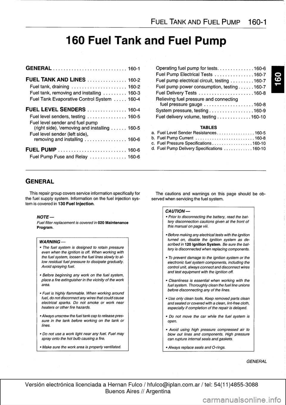
160
Fuel
Tank
and
Fuel
Pump
GENERAL
.
.
.
.
.
.
...........
.
....
.
.
.
.
.
.
160-1
Operating
fuel
pump
for
tests
.
.
.
.
.
.
.......
.160-6
Fuel
Pump
Electrical
Tests
.
.
.
.
.
.
.
...
.
.
.
.
.
160-7
FUEL
TANK
AND
LINES
..
.
.
.
..........
160-2
Fuel
pump
electrical
circuit,
testing.
...
.
.
.
.
.
160-7
Fuel
tank,
draining
..
.
.
.
.
.
.
.
.
.
..........
160-2
Fuel
pump
power
consumption,
testing
.
.
.
.
.
.
160-7
Fuel
tank,
removing
and
installing
.........
160-3
Fuel
Delivery
Tests
....
.
.
.
...
.
.....
.
.
.
..
160-8
Fuel
Tank
Evaporative
Control
System
.....
160-4
Relieving
fuel
pressure
and
connecting
fuel
pressure
gauge
..
.
...........
.
.
.
..
160-8
FUEL
LEVEL
SENDERS
.
.
.
.
.
.......
.
.
.
160-4
System
pressure,
testing
.................
160-9
Fuel
level
senders,
testing
.
.
.
.
.
.......
.
.
.
160-5
Fuel
delivery
volume,
testing
.............
160-10
Fuel
leve¡
sender
and
fuel
pump
(right
side),
emoving
and
installing
.
.
.
.
.
.
160-5
TABLES
Fuel
leve¡
sender
(left
side),
a
.
FuelLeve¡
Sender
Resistances
...........
.
.
..
.160-5
removing
and
installing
.........
.
.
.
.
.
.
.
160-6
b
.
Fuel
Pump
Current
...
.................
..
...
160-8
c
.
Fuel
Pressure
Specifications
..............
.
..
160-10
FUEL
PUMP
.
.
.
................
.
.
.
.
.
.
.
160-6
d
.
Fuel
Pump
Delivery
Specifications
.........
.
..
160-10
Fuel
Pump
Fuse
and
Relay
.
.
.
....
.
.
.
.
.
.
.
160-6
GENERAL
This
repair
group
covers
service
information
specifically
for
The
cautions
and
warnings
on
this
page
should
beob
the
fuel
supply
system
.
Information
on
the
fue¡
injection
sys-
served
when
servicing
the
fuel
system
.
tem
is
covered
in
130
Fuel
Injection
.
NOTE-
Fue¡
filter
replacement
is
covered
in
020
Maintenance
Program
.
WARNING
-
"
The
fuel
system
is
designed
to
retain
pressure
even
when
the
ignition
isoff
.
When
working
with
the
fuel
system,
loosen
the
fuel
lines
slowly
toal-
low
residual
fuel
pressure
to
dissipate
gradually
.
Avoid
spraying
fuel
.
"
Before
beginning
any
work
on
the
fuel
system,
place
a
tire
extinguisher
in
the
vicinity
of
the
work
area
.
"
Fuel
is
highly
flammable
.
When
working
around
fuel,
do
not
disconnect
any
wires
that
could
cause
electrical
sparks
.
Do
not
smoke
or
work
near
heaters
or
other
tire
hazards
.
"
Always
unscrew
the
fuel
tank
cap
to
release
pres-
sure
in
the
tank
before
working
on
the
tank
or
fines
.
"
Do
not
use
a
work
light
near
any
fuel
.
Fuel
may
spray
onto
the
hot
bulb
causing
a
tire
.
"
Make
sure
the
work
area
is
properly
ventifated
.
FUEL
TANK
AND
FUEL
PUMP
160-1
CAUTION-
"
Prior
to
disconnecting
the
battery,
read
the
bat-tery
disconnection
cautions
given
at
the
front
of
this
manual
onpage
viü
.
"
Before
making
any
electrical
tests
with
the
ignition
tumed
on,
disable
the
ignition
system
as
de-
scribed
in
120
Ignition
System
.
Be
sure
the
bat-tery
is
disconnected
when
replacing
components
.
"
To
prevent
damage
to
the
ignition
system
or
the
electronic
fuel
system
components,
including
the
control
unit,
aiways
connect
and
disconnect
wires
and
test
equipment
with
the
ignition
off
.
"
Cleanliness
is
essential
when
working
with
the
fuel
system
.
Thoroughly
clean
the
fuel
fine
unionsbefore
disconnecting
any
of
the
fines
.
"
Use
only
clean
tools
.
Keep
removed
parts
clean
and
sealed
or
covered
with
a
clean,
lint-free
cloth,
especially
if
completion
of
the
repair
is
delayed
.
"
Do
not
move
the
car
while
the
fuel
system
is
open
.
"
Avoid
using
high
pressure
compressed
air
to
blow
out
fines
and
componente
.
High
pressure
can
rupture
infernal
seals
and
gaskets
.
"
Always
replace
seals
and
O-rings
.
GENERAL
Page 219 of 759
Clutch,
inspecting
and
installing
1
.
Inspect
clutch
disc
for
wear,
cracks,
loose
rivets,
con-
tamination
or
excessive
runout
(warping)
.
Replace
if
necessary
.
2
.
Inspect
flywheel
for
scoring,
hot
spots,
cracks
or
loose
or
worn
guide
pins
.
Replace
flywheel
if
any
faults
are
found
.
WARNING
-
If
flywheel
is
removed
from
vehicle,
use
new
bolts
duríng
installation
.
The
old
stretch-typebolts
should
not
be
reused
.
3
.
Inspecttransmission
pilot
bearing
in
end
of
crankshaft
.
The
bearing
should
rotate
smoothly
without
play
.
If
nec-
essary,
replace
as
described
later
.
4
.
Inspect
and
clean
releasebearing
lever
.
Apply
a
thin
coat
of
grease
to
releasebearíng
lever
contact
points
.
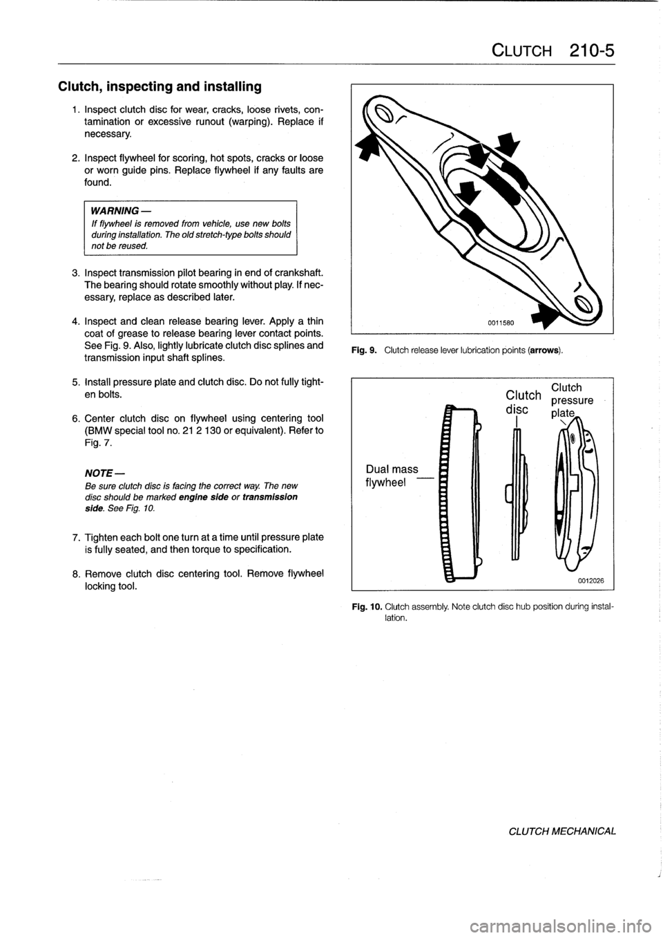
See
Fig
.
9
.
Also,
lightly
lubricate
clutch
disc
splines
and
transmission
inputshaft
splínes
.
5
.
Install
pressure
plate
and
clutch
disc
.
Do
not
fully
tight-
en
bolts
.
6
.
Center
clutch
disc
on
flywheel
using
centering
tool
(BMW
special
tool
no
.
21
2
130
or
equivalent)
.
Refer
to
Fig
.
7
.
NOTE-
Be
sure
clutchdísc
is
facing
the
correct
way
.
The
new
disc
should
bemarked
engine
sfde
or
transmission
side
.
See
Fig
.
10
.
7
.
Tighten
each
bolt
one
turn
at
a
time
until
pressure
plate
is
fully
seated,
and
then
torque
to
specification
.
8
.
Remove
clutch
disc
centering
tool
.
Remove
flywheel
locking
tool
.
Fig
.
9
.
Clutch
release
lever
lubrication
points
(arrows)
.
CLUTCH
210-
5
Clutch
Clutch
pressure
disc
plate
0012026
Fig
.
10
.
Clutch
assembly
Note
clutch
disc
hub
position
during
instal-
lation
.
CLUTCH
MECHANICAL