Headlight assembly BMW M3 1998 E36 Workshop Manual
[x] Cancel search | Manufacturer: BMW, Model Year: 1998, Model line: M3, Model: BMW M3 1998 E36Pages: 759
Page 304 of 759
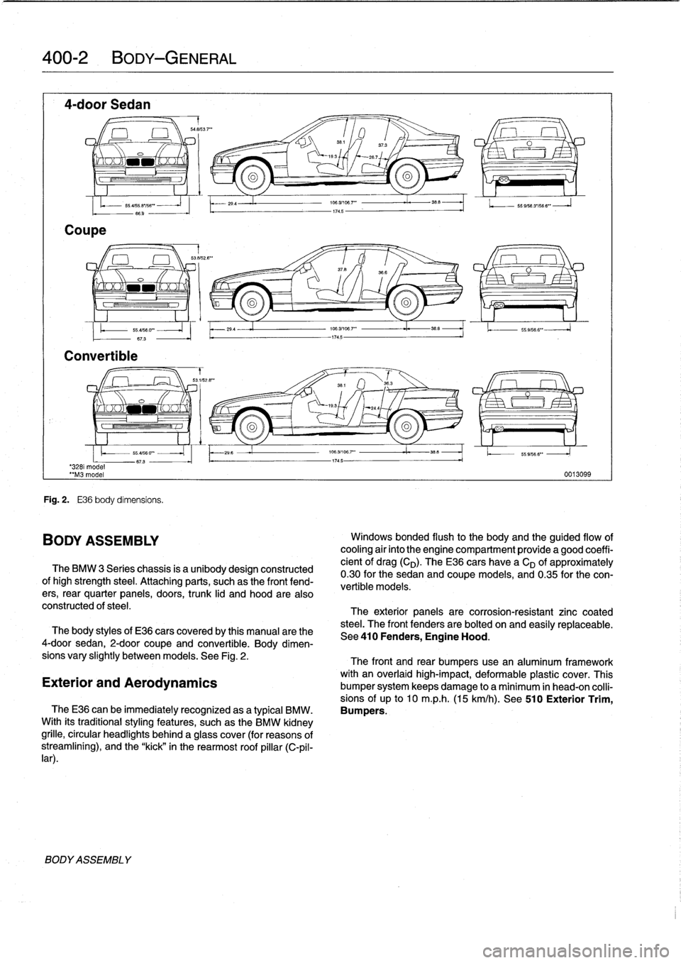
400-2
BODY-GENERAL
4-door
Sedan
Coupe
-
saas3
.7""
351
/
37
.3
O
I
x
`-193
267
o
oa
'3281
model
"M3
model
Convertible
BODYASSEMBLY
55
ass
.e
iss
""
-
66
.9
-
Fig
.
2
.
E36
body
dimensíons
.
BODY
ASSEMBLY
29
.4
29
4
The
BMW
3
Series
chassis
is
a
unibodydesign
constructed
ofhigh
strength
steel
.
Attaching
parts,
suchas
the
front
fend-
ers,
rear
quarter
panels,
doors,
trunk
lid
and
hood
are
also
constructed
of
steel
.
706
.31108
.7"
I
38
.5
174
.5
174
.5
O
oo
196
.3/106
.7'
"
35_5
1.
.
55
.9,566
".
106
.3/196
.7""
i.
358
-1745-
55
9/56
3'/56
6"
-
J
0013099
Windows
bonded
flush
to
the
body
and
the
guided
flow
of
cooling
air
into
the
engine
compartment
provide
a
good
coeffi-
cient
of
drag(CD)
.
TheE36
cars
have
a
CD
of
approximately
0
.30for
the
sedan
and
coupe
models,
and
0
.35
for
the
con-
vertible
models
:
The
exterior
panels
are
corrosion-resistant
zinc
coated
steel
.
The
front
fenders
are
bolted
on
and
easily
replaceabie
.
The
body
styles
of
E36
cars
coveredby
this
manual
arethe
See410
Fenders,
Engine
Hood
.
4-door
sedan,
2-door
coupe
and
convertible
.
Body
dimen-
sions
vary
slightly
betweenmodels
.
See
Fig
.
2
.
The
front
and
rear
bumpers
use
an
aluminum
framework
with
an
overlaid
high-impact,
deformable
plastic
cover
.
This
Exterior
and
Aerodynamics
bumper
system
keeps
damage
to
a
minimum
in
head-on
colli-
sions
of
up
to
10
m
.p
.h
.
(15
km/h)
.
See
510
Exterior
Trim,
TheE36
can
be
immediatelyrecognized
asa
typical
BMW
.
Bumpers
.
With
its
traditionalstyling
features,
suchas
the
BMW
kidney
grille,
circular
headlights
behind
a
glass
cover
(for
reasons
of
streamliníng),
and
the
"kick"
in
the
rearmost
roof
pillar
(C-pil-
lar)
.
Page 329 of 759
BMW
emblem,
removing
and
installing
The
procedure
given
below
applies
to
both
front
and
rear
emblems
.
1
.
Wrap
and
of
a
screwdriver
with
tape
.
CAUTION-
Protect
hood
paint
by
coveringarea
aroundem-
blem
with
tape
.
2
.
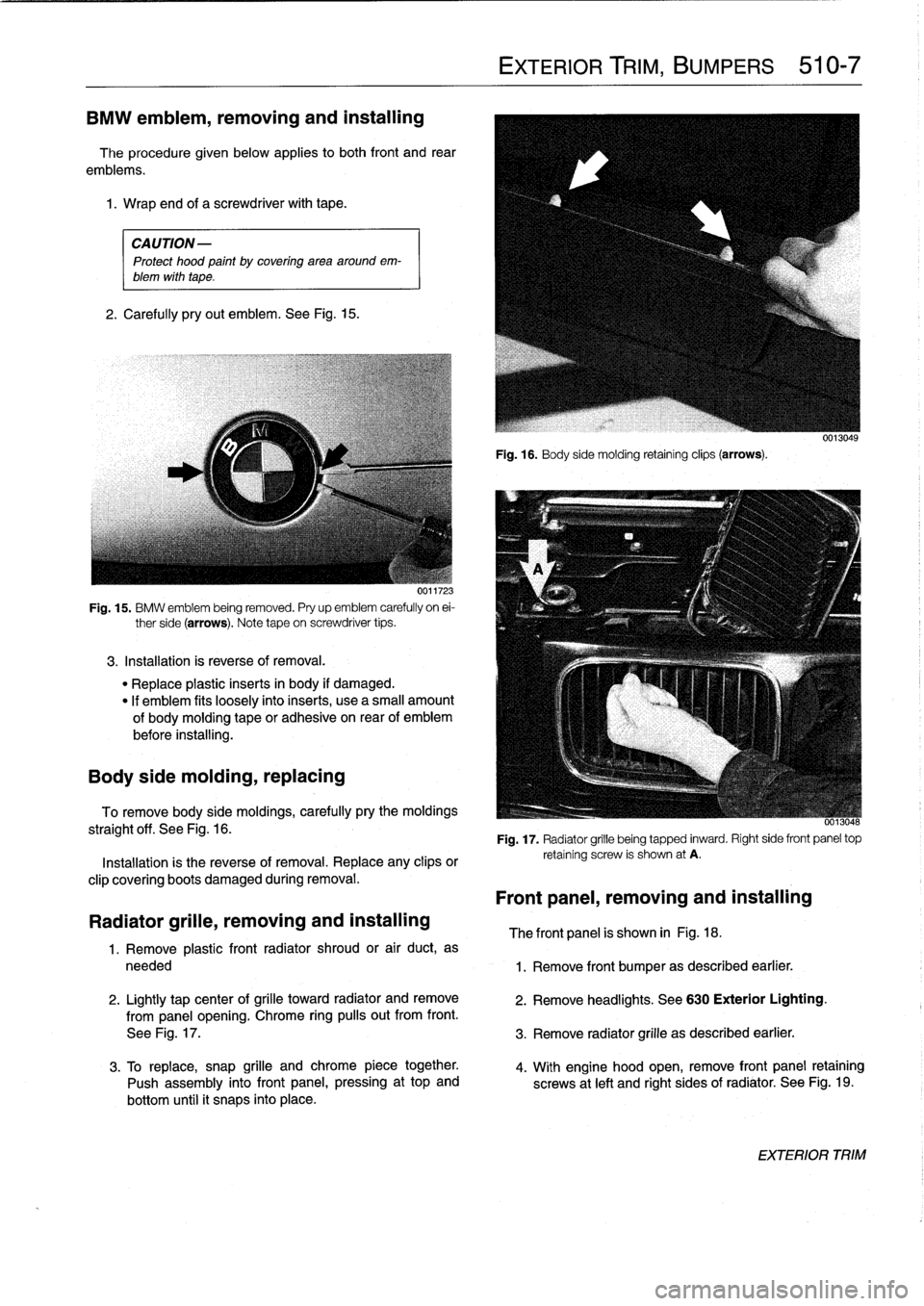
Carefully
pryout
emblem
.
See
Fig
.
15
.
UVI1'¿.
Fig
.
15
.
BMW
emblem
being
removed
.
Pry
up
emblem
carefully
on
ei-
ther
side
(arrows)
.
Note
tape
on
screwdriver
tips
.
3
.
Installation
is
reverse
of
removal
.
"
Replace
plastic
inserts
in
body
if
damaged
.
"
If
emblem
fits
loosely
intoinserts,
use
a
small
amount
of
bodymoldingtape
or
adhesiva
on
rear
of
emblem
before
installing
.
Body
side
molding,
replacing
To
remove
body
side
moldings,
carefully
pry
the
moldings
straight
off
.
See
Fig
.
16
.
Installation
is
the
reverse
of
removal
.
Replace
any
clips
or
clip
covering
boots
damaged
during
removal
.
Radiator
grille,
removing
and
installing
1
.
Remove
plastic
front
radiator
shroud
or
air
duct,
as
needed
2
.
Lightly
tap
center
of
grilla
toward
radiator
andremove
from
panel
opening
.
Chrome
ring
pulís
out
from
front
.
See
Fig
.
17
.
3
.
To
replace,
snap
grille
andchrome
piece
together
.
Push
assembly
into
front
panel,
pressing
at
top
and
bottom
until
it
snaps
into
place
.
EXTERIOR
TRIM,
BUMPERS
510-7
Fig
.
16
.
Body
sida
molding
retainingclips
(arrows)
.
-
0013048
Fig
.
17
.
Radiator
grille
being
tapped
inward
.
Right
side
front
panel
top
retaining
screw
is
shown
at
A
.
Front
panel,
removing
and
installing
The
front
panel
is
shown
in
Fig
.
18
.
1
.
Remove
front
bumper
as
described
earlier
.
2
.
Remove
headlights
.
See
630
Exterior
Lighting
.
3
.
Remove
radiator
grille
as
described
earlier
.
4
.
With
engine
hood
open,
remove
front
panel
retaining
screws
at
left
and
right
sides
of
radiator
.
See
Fig
.
19
.
EXTERIOR
TRIM
Page 399 of 759
Tablea
.
E36
Component
Locations
Component
Model
Year
Location
Refer
to
Engine
Compartment
Light
Switch
1993-1996
Over
right
headlight
assembly
Fig
.
7
.
Engine
Control
Module
(ECM)
1992-1998
Right
rear
enginecompartment,
behind
bulkhead
panel
Fig
.
7
.
Engine
Control
Module
(System)
1992-1998
I
Power
distribution
box
Fig
.
2
.
Relay
Engine
Coolant
Leve¡
Sensor
1
1992-1998
1
Left
front
of
enginecompartment,
radiator
coolant
reservoir
Engine
Coolant
Temperature
1992-1998
I
Left
front
of
engine
under
intake
manifold
I
Fig
.
19
.
Sensor
Fig
.
20
.
Evaporative
Emission
Valve
1992-1998
Left
side
strut
Power
area
Evaporator
Temperature
Sensor
1992-1998
Left
side
of
heater
box
EWS
II
Control
Module
1/1995
-
1998
Behind
glove
compartment
Fig
.
8
.
Fig
.
9
.
EWS
II
Ring
Antenna
1
1/1995
-
1998
1
At
ignition
cylinder
EWS
II
Transmitter
Module
1/1995
-
1998
Right
side
of
steering
column
in
auxiliaryrelay
panel
Fig
.
3
.
Exhaust
Gas
Flap
Valve
1996-1998
Left
rear
muffler
area
Flasher
Relay
1992-1998
Power
distribution
box
Fig
.
2
.
Foglight
Relay
1
1992-1998
1
Power
distribution
box
1
Fig
.
2
.
Fresh
Air
FlapActuator
1
1992
1
Right
side
of
heater
box
Fresh
Air
FlapActuator
1
1993-1995
1
Below
right
side
heater
box
Fresh
Air
FlapActuator
1
1996-1998
Below
left
side
heater
box
Fuel
Injectors
1992
-
1998
Top
left
side
of
engine
Fuel
Leve¡
Sensor,
Left
1
1992-1998
/
Under
left
side
of
rear
seat
infuel
tank
Fuel
Leve¡
Sensor,
Right
1
1992-1998
1
Under
right
side
of
rear
seat
in
fuel
tank
1
Fig
.
28
.
Fuel
Pump
1
1992-1998
1
Under
right
side
of
rear
seat
in
fuel
tank
1
Fig
.
28
.
Fuel
Pump
Relay
1
1992-1998
1
Power
distribution
box
1
Fig
.
2
.
Fuel
Pump/Start
Identification
Relay
1994
-
1996
Power
distribution
box
Fuel
Tank
Pressure
Sensor
1
1997-1998
1
Right
rear
wheel
well
behind
trim
liner
ELECTRICAL
COMPONENT
LOCATIONS
610-13
Fuse
andRelay
x(Power
11992-1998
I
Left
side
of
engine
compartment
I
Fig
.
2
.
Distribution
Box
Fig
.
7
Fig
.
10
.
Gas
Filler
LockMotor
1992-1998
Right
side
of
luggage
compartment
Gear
Position/Neutral
Safety
Switch
1992-1998
Next
to
gear
shift
lever
in
center
console
Fig
.
29
.
(Automatic
Transmission
Range
Switch)
Glove
Compartment
Lock
Motor
1994-1998
Behind
glove
compartment
Grounds
G
100
1995-1998
Front
of
left
front
fender
(headlights)
Fig
.
22
.
G
101
1992-1998
Front
of
right
front
fender
Continued
COMPONENT
LOCATIONS
Page 429 of 759
612
Switches
and
Electrical
Accessories
GENERAL
.
.
.
.
.
.
.
.
.
...
.
.
.
.
.
...
.
......
.612-1
Headlight
switch,
replacing
..
.
...
.
.
.
.
.
.
.
.
.
612-5
Foglight
switch,
replacing
....
.
.
.
.
.
.
.
.
.
.
.
.
.
612-5
INTERIOR
SWITCHES
.
.
...
.
.
.
.
.
.
.
.....
612-1
Hazard
warning
switch,
replacing
.
.
.
.
.
.
.
.
.
.612-5
Turn
signal
switch
and
wiper
switch,
Powerwindow
switch,
replacing
.
.
.
...
.
.
.
.
.
612-5
replacing
.
.
.
.
.
.
.
...
.
.
.
.....
.
....
.
.
.
.
612-1
Outside
mirrorswitch,
replacing
.
.
.
.
.....
.
.
.612-6
Ignition
Switch
Assembly
.
.
.
.
.
.
.
.
....
.
...
612-3
Ignition
electrical
switch,
replacing
.
...
.
....
612-3
INTERIOR
LIGHTS
.
.
................
.
..
612-6
Ignition
lock
cylinder,
replacing
.
.
.
.
.....
.
..
612-4
Dome
light,
rear
map
lights,
trunk
light,
Headlight
and
Foglight
Switch
Assembly
.
.
.
.
612-5
replacing
bulbs
.
......
.
.
.
.
.
.
.
.
.
.....
.
.612-7
GENERAL
Turn
signal
switch
and
wiper
switch,
replacing
Thissection
covers
replacement
of
interior
switches
and
accessories
.
The
procedures
for
removing
the
turn
signal
stalk
switch
and
the
wiper
system
stalk
switchare
similar
.
When
working
on
electrical
switches,
always
disconnect
the
negative
(-)
cable
from
the
battery
and
insulate
the
cable
end
to
prevent
accidental
re-connection
.
CAUTION-
Prior
to
disconnectiog
the
battery,
read
the
battery
disconnection
cautions
given
at
the
front
of
this
manual
on
page
viii
.
WARNING
-
The
cars
covered
by
this
manual
are
equipped
with
a
Supplemental
Restraint
System
(SRS)
that
auto-'
matically
deploys
one
or
more
airbags
.
Each
airbag
unit
houses
an
explosive
powerful
charge
.
Any
work
involving
the
SRS
system
should
only
be
per-
formed
byan
authorized
BMW
dealer
.
Making
re-
pairs
without
the
proper
knowledge
and
special
test
equipment
may
cause
serious
personal
injury
.
See
721
Airbag
System
(SRS)
3
.
With
front
wheels
pointed
straight
ahead,
remove
steer-
"
Testing
and
replacement
information
for
the
oil
ores-
¡ng
wheel
.
See
320
Steering
and
Wheel
Alignment
.
sure
switch
is
covered
in
119
Lubrication
System
.
NOTE-
"
Wirfng
diagramscan
be
found
in
Electrical
Wiring
Diagrams
.
"
Fuse,
relay
and
electrical
component
locations
can
be
found
in
610
Electrical
Component
Locations
.
"
Replacement
information
for
thetransmission
gear
position/neutral
safety
switch
is
covered
in
250
Gear-
shift
Unkage
.
INTERIOR
SWITCHES
NOTE
-
To
preventmarring
interior
trim,
wrap
the
tips
of
screw-
drivers
and
pliers
with
tape
beforeprying
out
switches
or
electrical
accessories
.
SWITCHES
AND
ELECTRICAL
ACCESSORIES
612-1
1
.
Disconnect
negative
(-)
cable
from
battery
and
cover
terminal
with
insulating
material
.
2
.
Remove
airbag
unit
from
steering
wheel
.
See
721
Air-
bag
System
(SRS)
.
Store
airbag
unit
in
a
safe
placew¡th
pad
facing
up
.
NOTE
-
To
helo
with
reassembly,
mark
steering
wheel
and
col-
umn
before
disassembly
.
4
.
Remove
trim
panel
from
lower
left
side
of
instrument
panel
.
See513
Interior
Trim
.
INTERIOR
SWITCHES
Page 432 of 759
612-4
SWITCHES
AND
ELECTRICAL
ACCESSORIES
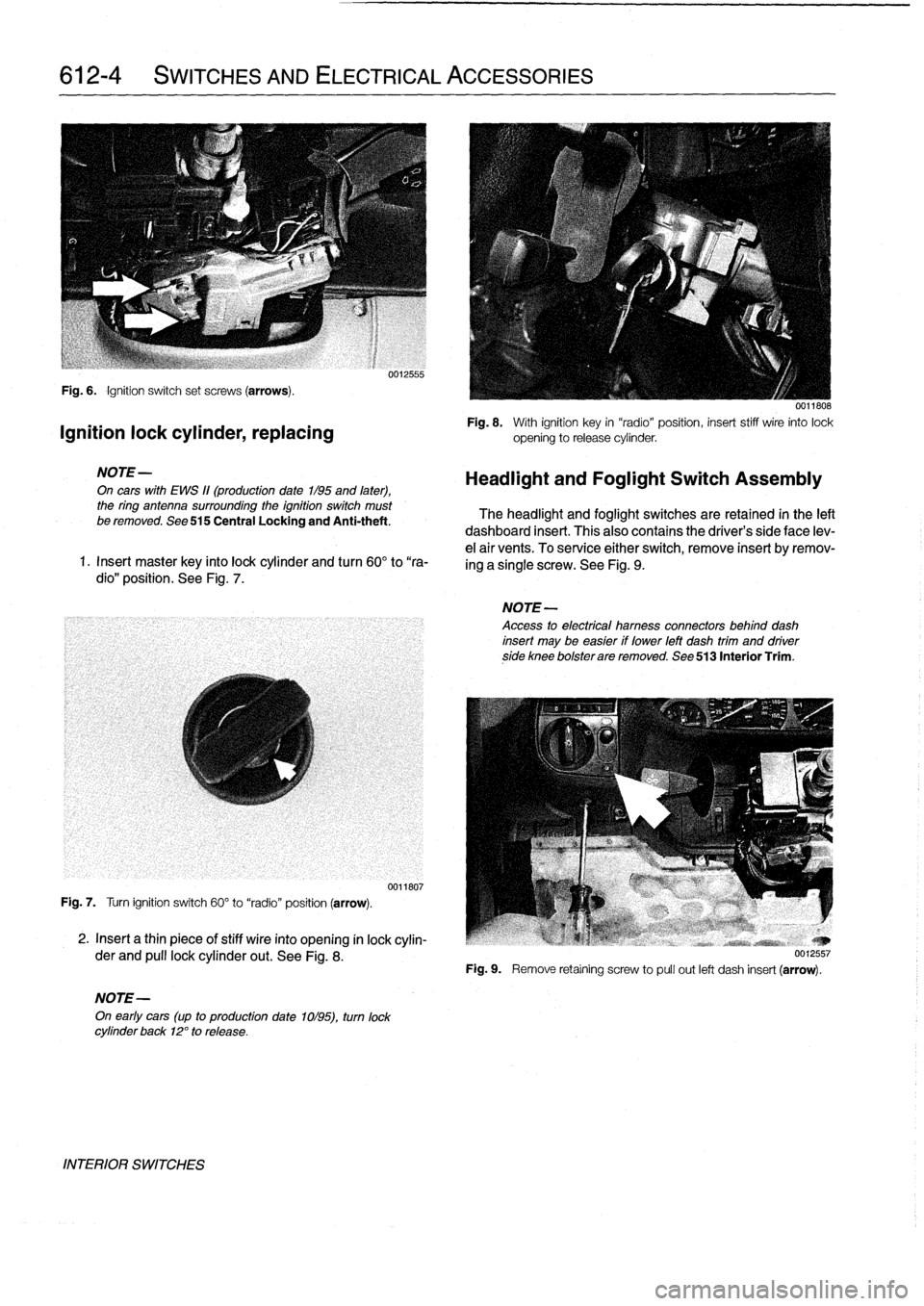
Fig
.
6
.
Ignition
switch
set
screws
(arrows)
.
Ignition
lock
cylinder,
replacing
NOTE-
On
cars
with
EWS
11(production
date
1/95
and
later),
the
ring
antenna
surrounding
the
ignition
switch
must
be
removed
.
See
515
Central
Locking
and
Anti-theft
.
1
.
Insert
master
key
finto
lock
cylinder
and
turn
60°
to
"ra-
dio"
position
.
See
Fig
.
7
.
Fig
.
7
.
Turn
ignition
switch
60°
to
"radio"
position
(arrow)
.
2
.
Insert
a
thin
piece
of
stiff
wire
into
opening
in
lock
cylin-
der
and
pull
lockcylinder
out
.
See
Fig
.
8
.
NOTE-
On
early
cars
(up
to
production
date
1ol95),
turn
lock
cylinder
back
12°
to
release
.
INTERIOR
SWITCHES
0012555
0011807
0011808
Fig
.
8
.
With
ignition
key
in
"radio"position,
insert
stiff
wire
into
lock
opening
to
release
cylinder
.
Headlight
and
Foglight
Switch
Assembly
The
headlight
and
foglight
switches
are
retained
in
the
left
dashboard
insert
.
This
alsocontains
the
driver's
side
face
lev-
e¡
air
vents
.
To
service
either
switch,
remove
insert
byremov-
ing
a
single
screw
.
See
Fig
.
9
.
NOTE-
Access
to
electrical
hamess
connectors
behind
dash
insert
may
be
easier
if
lower
left
dash
trim
and
driverside
knee
bolsterare
removed
.
See
513
Interior
Trim
.
Fig
.
9
.
Remove
retaíning
screw
to
pull
out
left
dash
insert
(arrow)
.
Page 441 of 759
FRONT
LIGHTING
.
...........
.
....
.
.
.
.
630-1
Headlight
buib,
replacing
............
.
.
.
.
630-1
Headlight
assembly,
removing
and
installing
.......
.
....
.
.
.
.
630-2
Foglight
assembly,
removing
and
installing
..
630-3
Front
turn
signal
assembly,
removing
and
installing
.....
.
.
.
........
630-4
GENERAL
The
headlight
and
foglight
assemblies
usehalogen
bulbs
.
To
ensure
the
longevity
of
halogen
bulbs,
the
bulb
glass
should
not
be
handied
.
Dirt
and
skin
oíls
may
cause
a
bulbto
fail
prematurely
.
If
necessarywipe
bulb
using
a
clean
cloth
dampened
with
rubbing
alcohol
.
NOTE-
Use
only
original
equipment
replacement
bulbs
.
Non-
original
equipment
bulbs
may
cause
false
failure
read-
ings
on
the
check
control
display
(where
applicable)
.
WARNING
-
INhenworking
on
electrical
systems,
remove
the
fuse
protecting
the
circuit
under
repair
.
See
610
Electrical
Component
Locations
.
FRONT
LIGHTING
Headlight
bulb,
replacing
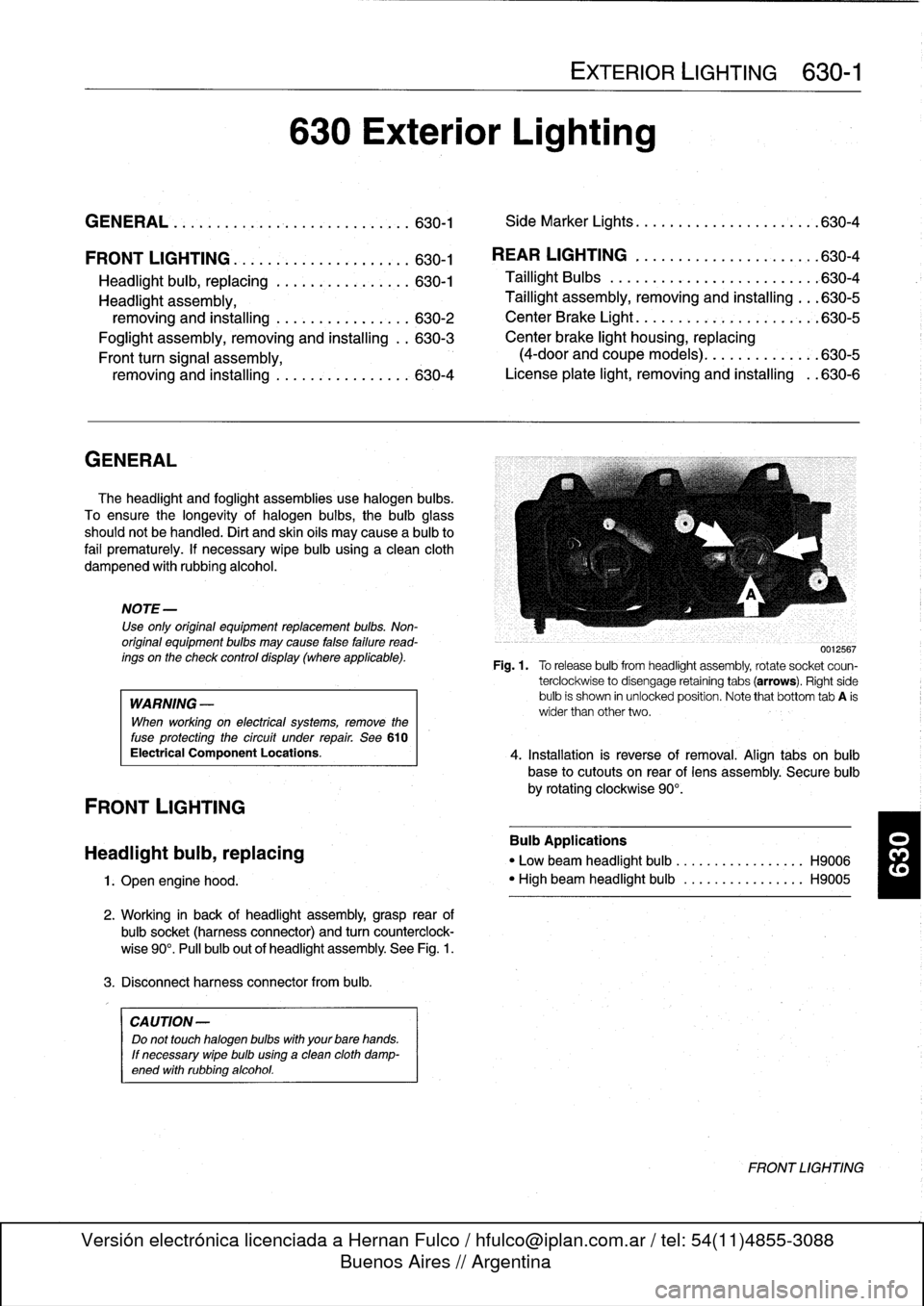
1
.
Open
engine
hood
.
2
.
Working
in
back
of
headlight
assembly,grasp
rear
of
bulbsocket
(harnessconnector)
and
turn
counterclock-
wise
90°
.
Pull
bulb
out
of
headlight
assembly
.
See
Fig
.
1
.
3
.
Disconnect
harness
connector
from
bulb
.
CA
UTION-
Do
not
touch
halogen
bubs
with
yourbare
hands
.
If
necessary
wipe
bulb
using
a
clean
cloth
damp-
ened
with
rubbing
alcohol
.
630
Exterior
Lighting
EXTERIOR
LIGHTING
630-1
GENERAL
.
.
.
.
...
.
................
.
.
.
.
630-1
Side
Marker
Lights
.......
.
.
.
.
.
.......
.
..
630-4
REAR
LIGHTING
.
......
.
.
.
.
.
.
.
...
.
.
.
..
630-4
Taillight
Bulbs
..........
.
.
.
.
.
.....
.
.
.
.
.
630-4
Taillight
assembly,
removing
and
installing
.
.
.
630-5
CenterBrake
Light
.......
.
.
.
.
.
.
.
.
.
.
.
.
.
.
.
630-5
Center
brake
light
housing,
replacing
(4-door
and
coupe
models)
.
.
.
.
.......
.
.
.630-5
License
plate
light,
removingand
installing
.
.630-6
0012567
Fig
.1.
Torelease
bulbfrom
headlight
assembly,
rotate
socket
coun-
terclockwise
to
disengage
retaining
tabs
(arrows)
.
Right
side
bulb
is
shown
in
unlocked
position
.
Note
that
bottom
tab
A
is
wider
than
other
two
.
4
.
Installation
is
reverse
of
removal
.
Align
tabs
on
bulb
base
to
cutouts
on
rear
of
lens
assembly
.
Secure
bulb
by
rotating
clockwise
90°
.
Bulb
Applications
"
Low
beam
headlight
bulb
...
.
..
..
.........
H9006
"
High
beam
headlight
bulb
..
.
..
..
.........
H9005
FRONT
LIGHTING
Page 442 of 759
630-2
EXTERIOR
LIGHTING
Headlight
assembly,
removing
and
installing
CAUTION-
Followingheadlight
assembly
work
headlight
beam
aim
must
be
adjusted
using
special
equip-
ment
.
1
.
Left
side
:
Remove
air
filter
housing,
air
intake
duct,
and
air
mass
meter
.
See
100
Engine-General
.
2
.
Disconnect
harness
connectors
from
headlight
bulbs
.
3
.
Remove
front
turn
signal
.
See
Front
turn
signal
as-
sembly,
removingand
installing
later
in
this
repair
group
.
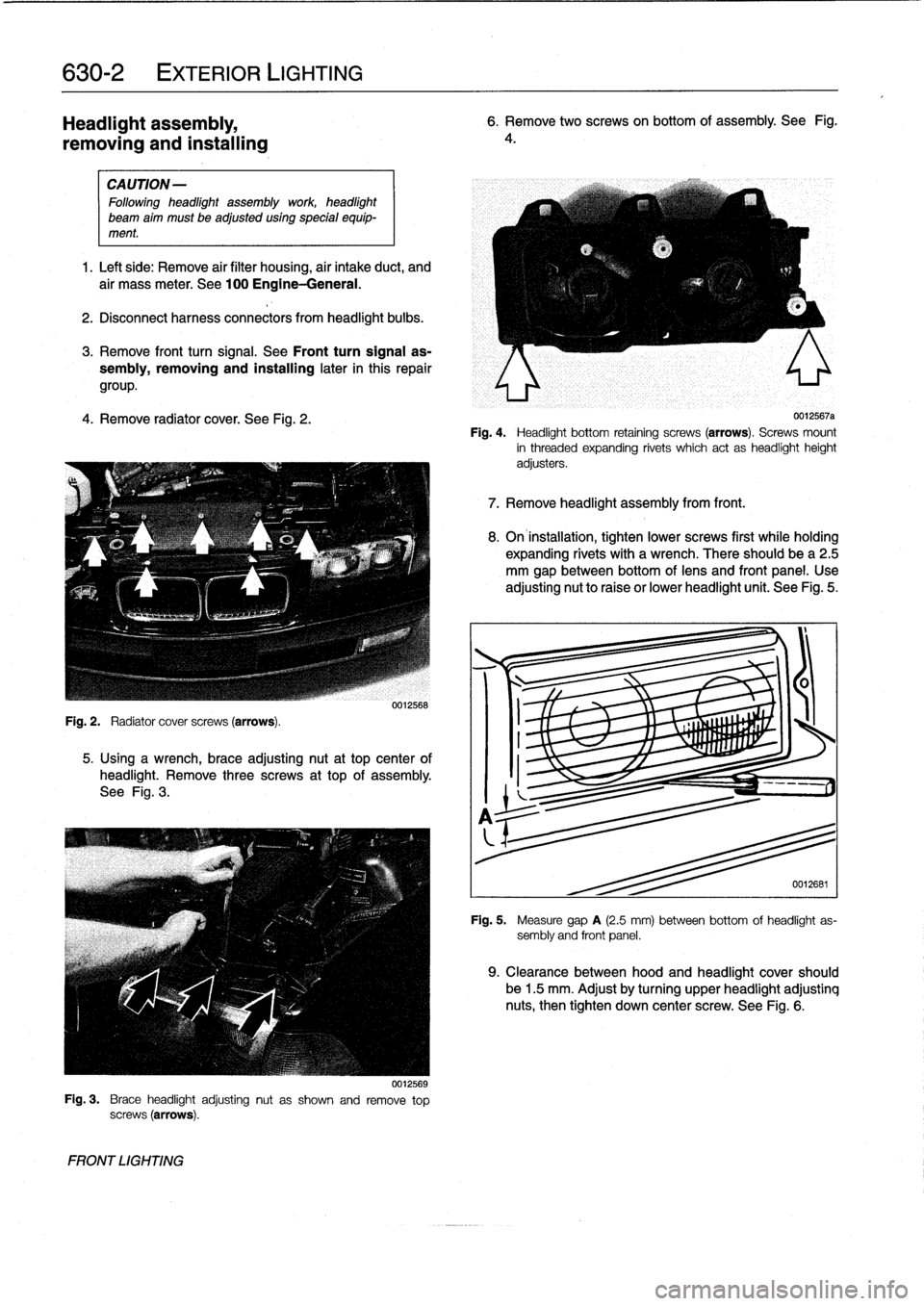
4
.
Remove
radiator
cover
.
See
Fig
.
2
.
5
.
Using
a
wrench,
brace
adjusting
nut
at
top
center
of
headlight
.
Remove
three
screws
at
top
of
assembly
.
See
Fig
.
3
.
Fig
.
3
.
Brace
headlightadjustingnut
as
shown
and
remove
top
screws
(arrows)
.
FRONT
LIGHTING
0012568
0012569
6
.
Remove
two
screwson
bottom
of
assembly
.
See
Fig
.
4
.
0012567a
Fig
.
4
.
Headlight
bottom
retaining
screws
(arrows)
.
Screws
mount
in
threaded
expanding
rivets
which
act
as
headlightheight
adjusters
.
7
.
Remove
headlight
assembly
from
front
.
8
.
On
installation,
tighten
lower
screws
first
while
holding
expanding
rivets
with
a
wrench
.
There
should
be
a
2
.5
mm
gap
between
bottom
oflens
and
front
panel
.
Use
adjusting
nut
to
raise
or
lower
headlight
unit
.
See
Fig
.
5
.
0012681
Fig
.
5
.
Measure
gap
A
(2.5
mm)
between
bottom
of
headlight
as-
sembly
and
front
panel
.
9
.
Clearance
between
hood
and
headlight
cover
should
be
1
.5
mm
.
Adjust
by
turning
upper
headlight
adjustinq
nuts,
then
tighten
down
center
screw
.
See
Fig
.
6
.
Page 443 of 759
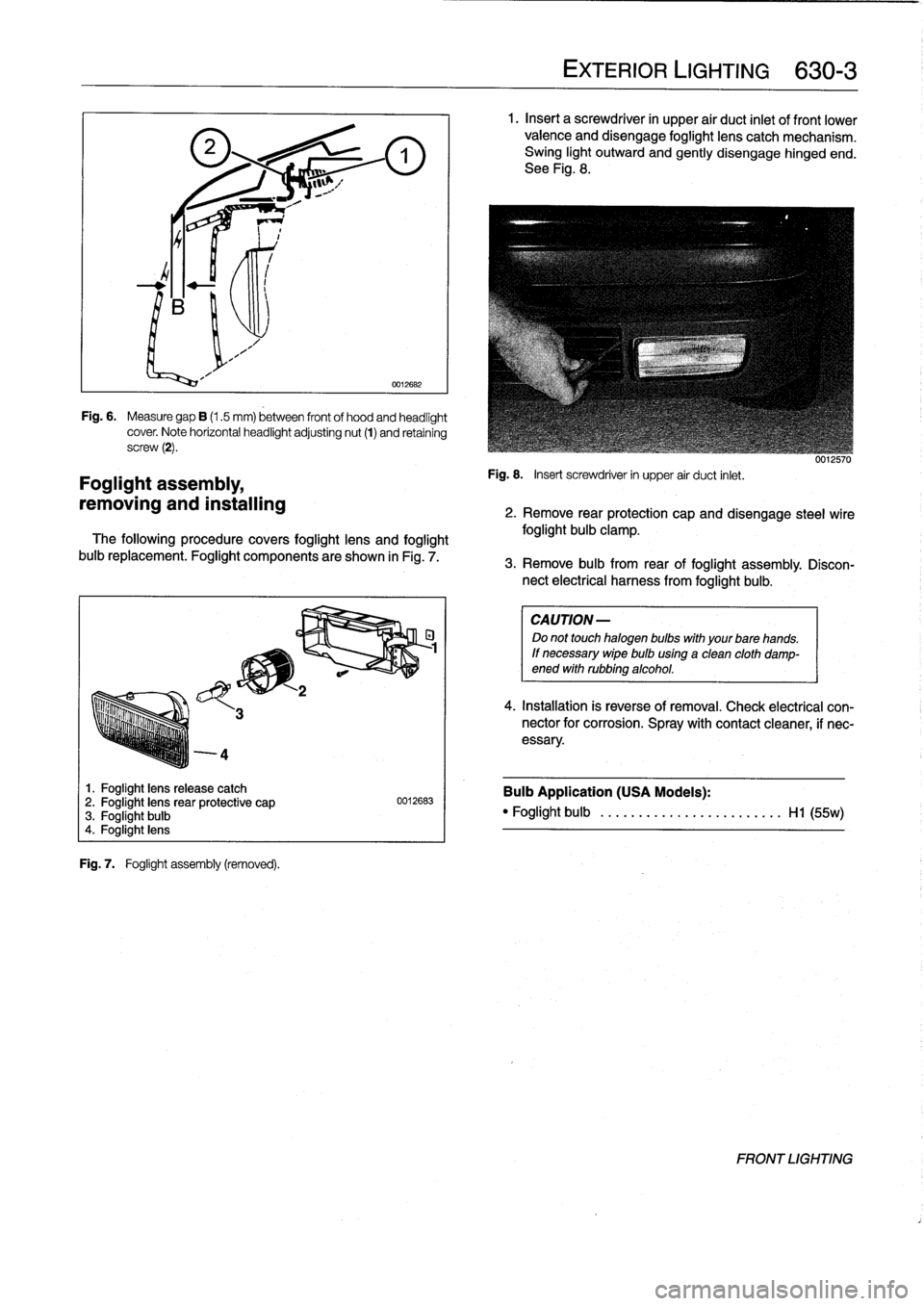
4
Foglight
assembly,
removing
and
installing
1
.
Foglight
lens
release
catch
2
.
Foglight
lensrear
protective
cap
3
.
Foglight
bulb
4
.
Foglight
lens
Fig
.
7
.
Foglight
assembly
(removed)
.
0012682
Fig
.
6
.
Measure
gap
B
(1.5
mm)
between
front
of
hood
and
headlight
cover
.
Note
horizontal
headlightadjusting
nut
(1)
and
retaining
screw
(2)
.
The
following
procedure
covers
foglight
lens
and
foglight
buib
replacement
.
Foglight
components
are
shown
in
Fig
.
7
.
0012683
EXTERIOR
LIGHTING
630-
3
1
.
Insert
a
screwdriver
in
upper
air
duct
inlet
of
front
lower
valence
and
disengage
foglight
lens
catch
mechanism
.
Swing
light
outward
and
gently
disengage
hinged
end
.
See
Fig
.
8
.
Fig
.
8
.
Insert
screwdriver
in
upper
air
duct
inlet
.
uu¡¿biu
2
.
Remove
rear
protection
capand
disengage
steel
wire
foglight
bulb
clamp
.
3
.
Remove
bulb
from
rear
of
foglight
assembly
.
Discon-
nect
electrical
harness
from
foglight
bulb
.
CAUTION
-
Do
not
touch
halogen
bulbs
with
yourbare
hands
.
If
necessary
wipe
buib
using
a
clean
cloth
damp-ened
withrubbing
alcohol
.
4
.
Installation
is
reverse
of
removal
.
Check
electrical
con-nector
for
corrosion
.
Spray
with
contact
cleaner,
if
nec-
essary
.
Bulb
Application
(USA
Models)
:
"
Foglight
bulb
......
...
..
...
..........
Hl
(55w)
FRONT
LIGHTING
Page 444 of 759
630-
4
EXTERIOR
LIGHTING
Front
turn
signal
assembly,
Side
Marker
Lights
removing
and
installing
Side
marker
lights
on
later
model
E36
cars
are
snapped
into
The
procedurebelow
also
includes
turn
signal
bulb
replace-
the
front
fenders
.
To
service,
carefully
pry
the
assembly
out
of
ment
.
the
fender,
then
detach
the
electrical
harness
connector
and
bulb
socket
.
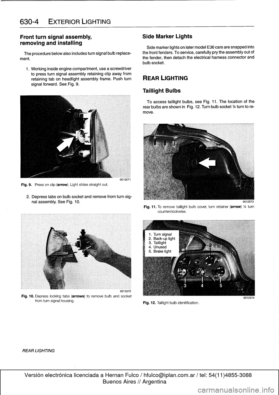
1
.
Working
inside
engine
compartment,usea
screwdriver
to
press
turn
signal
assembly
retaining
clip
away
from
retaining
tab
on
headlight
assembly
frame
.
Push
turn
REAR
LIGHTING
signal
forward
.
See
Fig
.
9
.
Fig
.
9
.
Press
on
clip
(arrow)
.
Light
slides
straight
out
.
REAR
LIGHTING
0012571
2
.
Depress
tabs
on
bulb
socket
and
remove
from
turn
sig-
nal
assembly
.
See
Fig
.
10
.
0012572
Fig
.
10
.
Depress
locking
tabs
(arrows)to
remove
bulb
and
socket
from
turn
signal
housing
.
Taillight
Bulbs
To
access
taillight
bulbs,
see
Fig
.
11
.
The
location
of
the
rear
bulbs
are
shown
in
Fig
.
12
.
Turn
bulb
socket
1
/4turn
to
re-
move
.
Fig
.
11
.
To
remove
taillight
bulb
cover,
turn
retainer
(arrow)
1
/a
turn
counterclockwise
.
Fig
.
12
.
Taillight
bulb
identification
.
0012574
Page 461 of 759
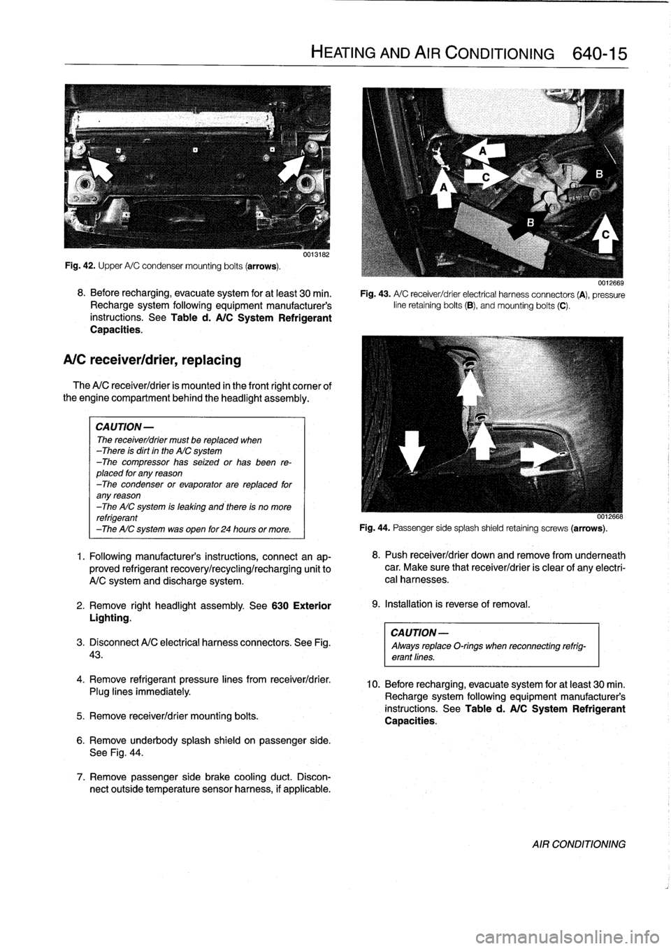
Fig
.
42
.
Upper
A/C
condensermounting
bolts
(arrows)
.
8
.
Before
recharging,
evacuate
system
for
at
least
30
min
.
Recharge
system
following
equipment
manufacturer's
instructions
.
See
Table
d
.
A/C
System
Refrigerant
Capacities
.
A/C
receiver/drier,
replacing
The
A/C
receiver/drier
is
mounted
in
the
front
right
cornee
of
the
engine
compartment
behind
the
headlight
assembly
.
CAUTION-
The
receiver/drier
must
be
replaced
when
-There
is
dirt
in
the
AIC
system
-The
compressor
has
seized
or
has
been
re-
placed
for
any
reason
-The
condenser
or
evaporator
are
replaced
for
any
reason
-The
AIC
system
is
leaking
and
there
is
no
more
refrigerant
-The
AIC
system
was
open
for
24
hours
or
more
.
1
.
Following
manufacturer's
instructions,
connectan
ap-
proved
refrigerant
recovery/recycling/recharging
unit
to
A/C
system
and
discharge
system
.
2
.
Remove
right
headlight
assembly
.
See
630
Exterior
Lighting
.
CAUTION-
3
.
Disconnect
A/C
electrical
harness
connectors
.
See
Fig
.
Always
replaceO-rings
when
reconnecting
refrig-
43
.
erant
lines
.
4
.
Remove
refrigerant
pressure
lines
from
receiver/drier
.
Plug
lines
immediately
.
5
.
Remove
receiver/drier
mounting
bolts
.
0013182
6
.
Remove
underbody
splash
shield
on
passenger
side
.
See
Fig
.
44
.
7
.
Remove
passenger
side
brake
cooling
duct
.
Discon-
nect
outside
temperature
sensor
harness,
if
applicable
.
HEATING
AND
AIR
CONDITIONING
640-15
0012669
Fig
.
43
.
A/
C
receiver/drier
electrical
harness
connectors
(A),
pressure
line
retaining
bolts
(B),
andmounting
bolts
(C)
.
0012668
Fig
.
44
.
Passenger
sidesplash
shield
retaining
screws
(arrows)
.
8
.
Push
receiver/drier
down
andremove
from
underneath
car
.
Make
sure
that
receiver/drier
is
clear
of
any
electri-
cal
harnesses
.
9
.
Installation
is
reverse
of
removal
.
10
.
Before
recharging,
evacuate
system
for
at
least
30
min
.
Recharge
system
following
equipment
manufacturer's
instructions
.
See
Table
d
.
A/C
System
Refrigerant
Capacities
.
AIR
CONDITIONING