BMW M3 COUPE 2004 E46 Owner's Manual
Manufacturer: BMW, Model Year: 2004, Model line: M3 COUPE, Model: BMW M3 COUPE 2004 E46Pages: 170, PDF Size: 2.62 MB
Page 141 of 170
141
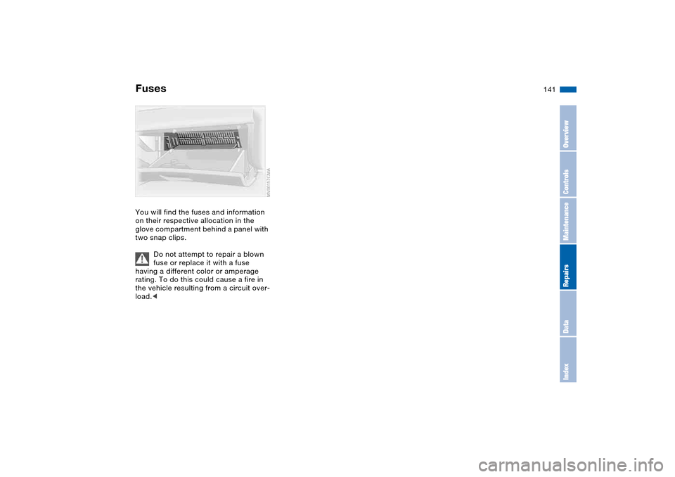
FusesYou will find the fuses and information
on their respective allocation in the
glove compartment behind a panel with
two snap clips.
Do not attempt to repair a blown
fuse or replace it with a fuse
having a different color or amperage
rating. To do this could cause a fire in
the vehicle resulting from a circuit over-
load.<
OverviewControlsMaintenanceRepairsDataIndex
Page 142 of 170
142Giving and receiving assistance
Receiving assistanceThe BMW Group's Mobile Service
offers you 24-hour assistance in the
event of a breakdown, even on week-
ends and holidays.
The telephone numbers of the Mobile
Service control center in your country
are listed in the BMW Dealer Directory.
If your vehicle has the necessary equip-
ment, you can contact the Mobile Ser-
vice or issue an emergency call using
buttons in the interior rearview mirror.
When an emergency call is initiated, a
telephone connection is established
with the general emergency call center.
In vehicles with activated BMW Assist
function, a telephone connection is set
up to the BMW Assist emergency call
center. If the current location of your
vehicle can be determined, this location
is transmitted to the BMW Assist emer-
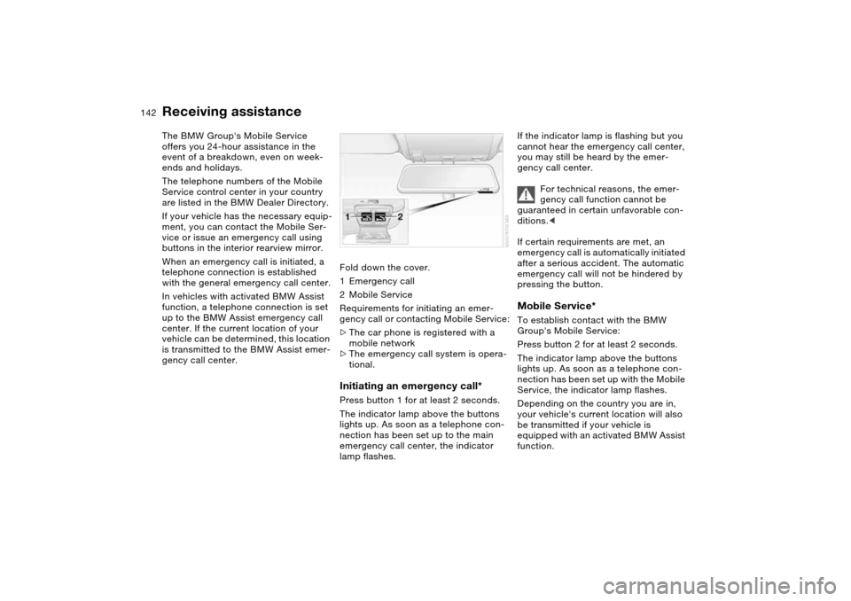
gency call center.Fold down the cover.
1Emergency call
2Mobile Service
Requirements for initiating an emer-
gency call or contacting Mobile Service:
>The car phone is registered with a
mobile network
>The emergency call system is opera-
tional.
Initiating an emergency call*Press button 1 for at least 2 seconds.
The indicator lamp above the buttons
lights up. As soon as a telephone con-
nection has been set up to the main
emergency call center, the indicator
lamp flashes.
If the indicator lamp is flashing but you
cannot hear the emergency call center,
you may still be heard by the emer-
gency call center.
For technical reasons, the emer-
gency call function cannot be
guaranteed in certain unfavorable con-
ditions.<
If certain requirements are met, an
emergency call is automatically initiated
after a serious accident. The automatic
emergency call will not be hindered by
pressing the button.Mobile Service*To establish contact with the BMW
Group's Mobile Service:
Press button 2 for at least 2 seconds.
The indicator lamp above the buttons
lights up. As soon as a telephone con-
nection has been set up with the Mobile
Service, the indicator lamp flashes.
Depending on the country you are in,
your vehicle's current location will also
be transmitted if your vehicle is
equipped with an activated BMW Assist
function.
Page 143 of 170
143
Jump-startingWhen your battery is discharged, you
can use two jumper cables to start your
vehicle with power from the battery in a
second vehicle. You can also use the
same method to help start another
vehicle. Use only jumper cables with
fully insulated handles on the terminal
clamps.
Do not touch high-voltage wiring
and cables on a running engine.
Contact with components carrying high
voltage can be harmful or fatal.
Carefully observe the following instruc-
tions to avoid personal injury and/or
damage to one or both vehicles.
approximately the same capacity –
measured in Ah. This information is
provided on the battery
2. Stop the engine of the support vehi-
cle
3. Switch off all electrical components
in both vehicles.
Make absolutely certain that there
is no contact between the body-
work of the two vehicles, otherwise
there is a short circuit hazard.<
Connecting the jumper cables
Always adhere to this sequence
when connecting jumper cables;
failure to observe this procedure can
lead to sparks at the battery terminals
and pose an injury hazard.<
The auxiliary jump-starting terminal
located in your BMW's engine compart-
ment acts as the positive battery termi-
nal. Refer to the engine compartment
overview on page 120. The cover of this
auxiliary terminal is marked with a +.
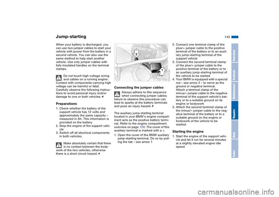
1. Open the cover of the BMW auxiliary
jump-starting terminal. Do so by pull-
ing the tab – see arrow 1
2. Connect one terminal clamp of the
plus/+ jumper cable to the positive
terminal of the battery or to an auxil-
iary jump-starting terminal of the
support vehicle
3. Connect the second terminal clamp
of the plus/+ jumper cable to the
positive terminal of the battery or to
an auxiliary jump-starting terminal of
the vehicle to be started
4. Your BMW is equipped with a special
nut – see arrow 2 – to serve as the
ground or negative terminal.
Attach a terminal clamp of the
minus/– jumper cable to the negative
terminal of the support vehicle's bat-
tery or to a suitable ground on its
engine or bodywork
5. Attach the second terminal clamp of
the minus/– jumper cable to the neg-
ative terminal of the battery or to a
suitable ground on the engine or
bodywork of the vehicle to be
started.Starting the engine1. Start the engine of the support vehi-
cle and let it run for several minutes
at a slightly elevated engine idle
speed
OverviewControlsMaintenanceRepairsDataIndex
Page 144 of 170
144
2. Start the engine of the other vehicle
as usual.
If the first start attempt is not suc-
cessful, wait a few minutes before
another attempt in order to allow the
discharged battery to recharge
3. Allow the engines to run for several
minutes
4. Disconnect the jumper cables in
reverse sequence.
Have the battery recharged at your
BMW center as required.
Do not use spray starter fluids to
start the engine.<
Towing the vehicle
Always observe all applicable
towing laws and regulations.<
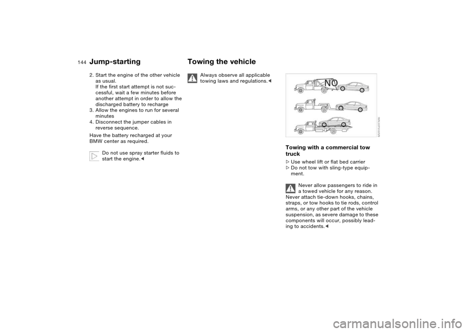
Towing with a commercial tow
truck>Use wheel lift or flat bed carrier
>Do not tow with sling-type equip-
ment.
Never allow passengers to ride in
a towed vehicle for any reason.
Never attach tie-down hooks, chains,
straps, or tow hooks to tie rods, control
arms, or any other part of the vehicle
suspension, as severe damage to these
components will occur, possibly lead-
ing to accidents.<
Jump-starting
Page 145 of 170
145
Towing the vehicle with the front
axle raisedVehicles with sequential manual gear-
box SMG:
With the ignition on, move the selector
lever to position N, then turn off the
ignition.Towing eyeletThe screw-in towing eyelet is stored in
the luggage compartment under the
floor mat and must remain in the vehi-
cle. It can be attached at the front or
rear of the vehicle.
The towing eyelet should not be used
to pull a vehicle out of deep snow, mud,
sand, etc.
Comply with all applicable towing laws
and regulations at all times.
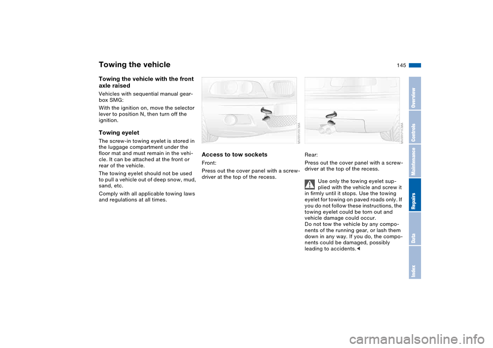
Access to tow socketsFront:
Press out the cover panel with a screw-
driver at the top of the recess.
Rear:
Press out the cover panel with a screw-
driver at the top of the recess.
Use only the towing eyelet sup-
plied with the vehicle and screw it
in firmly until it stops. Use the towing
eyelet for towing on paved roads only. If
you do not follow these instructions, the
towing eyelet could be torn out and
vehicle damage could occur.
Do not tow the vehicle by any compo-
nents of the running gear, or lash them
down in any way. If you do, the compo-
nents could be damaged, possibly
leading to accidents.<
Towing the vehicle
OverviewControlsMaintenanceRepairsDataIndex
Page 146 of 170
146
Keep the vehicles in line and avoid
towing at an offset angle. Ensure
that the towing strap connecting the
two vehicles is tight, with no slack,
before starting off.<
Use only a nylon towing strap to tow
the vehicle, since the inherent resil-
ience of this material helps protect both
vehicles from sudden jerking move-
ments.
The towed vehicle should always
be the lighter of the two vehicles.
If this is not the case, it will not be pos-
sible to control vehicle handling.<
Tow-startingFor instructions on jump-starting, refer
to page 143.
Never attempt to use your vehicle to
push another vehicle, since damage to
the energy-absorbing bumpers could
result.Towing the vehicle
Page 147 of 170
147
OverviewControlsMaintenanceRepairsDataIndex
Page 148 of 170
148
Page 149 of 170
149
Overview
Controls and features
Operation, maintenance
Owner service procedures
Technical data
Index
OverviewControlsMaintenanceRepairsDataIndex
Page 150 of 170
150
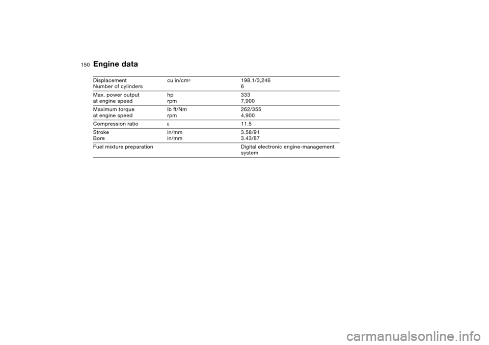
Engine dataDisplacement
Number of cylinderscu in/cm
3
198.1/3,246
6
Max. power output
at engine speedhp
rpm333
7,900
Maximum torque
at engine speedlb ft/Nm
rpm262/355
4,900
Compression ratioε11.5
Stroke
Borein/mm
in/mm3.58/91
3.43/87
Fuel mixture preparation Digital electronic engine-management
system